LBB 1925/10 Plena System Pre-Amplifier - WES Components
LBB 1925/10 Plena System Pre-Amplifier - WES Components
LBB 1925/10 Plena System Pre-Amplifier - WES Components
- No tags were found...

You also want an ePaper? Increase the reach of your titles
YUMPU automatically turns print PDFs into web optimized ePapers that Google loves.
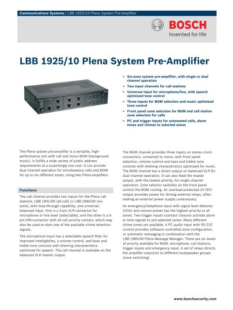
<strong>LBB</strong> <strong>1925</strong>/<strong>10</strong> <strong>Plena</strong> <strong>System</strong> <strong>Pre</strong>-<strong>Amplifier</strong> | 3Mains power supplyImpedanceS/N (flat at max volume)S/N (flat at min volme/muted)CMRRHeadroomSpeech filterPhantom power supplyLine inputConnectorSensitivityImpedanceS/N (flat at max volume)S/N (flat at min volume/muted)HeadroomMaster outputConnectorNominal levelImpedanceTape outputConnectorNominal levelImpedanceHeadphone outputConnectorNominal levelImpedanceZone relaysContacts voltageContacts currentInterconnection input / emergencyConnectorSensitivityImpedanceVOX thresholdInterconnection outputConnectorNominal levelImpedanceRelay contactsDC supply output voltage>1 kohm (mic); >5 kohm (line)>63 dB (mic); >70 dB (line)>75 dB>40 dB (50 Hz – 20 kHz)>25 dB-3 dB @ 315 Hz, high-pass,6 dB/oct16 V via 1.2 kohm, (mic mode only)3 xCinch, stereo converted to mono, unbalanced200 mV22 kohm>70 dB>75 dB>25 dB1 x3-pin XLR, balanced1 V
<strong>Plena</strong> <strong>System</strong> <strong>Pre</strong>-amplifier | Installation and Operating Manual | Important safeguards en | 3Important safeguards1 Read instructions - All the safety instructions for useshould be read before the system is operated.2 Retain instructions - The safety instructions andinstructions for use should be retained for futurereference.3 Heed warnings - All warnings on the unit and in theoperating instructions should be adhered to.4 Follow instructions - All operating instructions andinstructions for use should be followed.5 Cleaning - Unplug system units from the mains outletbefore cleaning. Do not use liquid cleaners or aerosolcleaners. Use a damp cloth for cleaning.6 Attachments - Do not use attachments notrecommended by the product manufacturer as they maycause hazards.7 Water and Moisture - Do not use this unit near water, forexample near a bathtub, washbowl, kitchen sink, orlaundry basket, in a wet basement, near a swimmingpool, in an unprotected outdoor installation or any areawhich is classified as a wet location.8 Accessories - Do not place this unit on an unstable stand,tripod, bracket or mount. This unit may fall, causingserious injury to a person and serious damage to theunit. Use only a stand, tripod, bracket or mountrecommended by the manufacturer, or sold with theproduct. Any mounting of the unit should follow themanufacturer's instructions, and should use a mountingaccessory recommended by the manufacturer. Anappliance and cart combination should be moved withcare. Quick stops, excessive force, and uneven surfacesmay cause the appliance and cart combination tooverturn.9 Ventilation - Openings in the enclosure, if any, areprovided for ventilation and to ensure reliable operationof the unit and to protect it from overheating. Theseopenings must not be blocked or covered. The unitshould not be placed in a built-in installation unlessproper ventilation is provided or the manufacturer'sinstructions have been adhered to.<strong>10</strong> Power sources - Units should be operated only from thetype of power source indicated on the marking label. Ifyou are not sure of the type of power supply you plan touse, consult your appliance dealer or local powercompany. For units intended to operate from batterypower, or other sources, refer to the "Installation andUser Instructions".11 Grounding or polarisation - This unit may be equippedwith a polarised alternating current line plug (a plughaving one blade wider than the other). This plug will fitinto the power outlet only one way. This is a safetyfeature. If you are unable to insert the plug fully into theoutlet, try reversing the plug. If the plug still fails to fit,contact your electrician to replace your obsolete outlet.Do not defeat the safety purpose of the polarised plug.Alternatively, this unit may be equipped with a 3-wiregrounding type plug having a third (grounding) pin.This plug will only fit into a grounding-type poweroutlet. This is a safety feature. If you are unable to insertthe plug into the outlet, contact your electrician toreplace your obsolete outlet. Do not defeat the safetypurpose of the grounding-type lug.12 Power-Cord Protection - Power supply cords should berouted so that they are not likely to be walked on orpinched by items placed upon or against them, payingparticular attention to cords and plugs, conveniencereceptacles, and the point where they exit from theappliance.13 Overloading - Do not overload outlets and extensioncords as this can result in a risk of fire or electrical shock.14 Object and Liquid Entry - Never push objects of anykind into this unit through openings as they may touchdangerous voltage points or short-out parts that couldresult in a fire or electric shock. Never spill liquid of anykind on the unit.15 Servicing - Do not attempt to service this unit yourself asopening or removing covers may expose to dangerousvoltage or other hazards. Refer all servicing to qualifiedservice personnel.16 Damage Requiring Service - Unplug the unit from theoutlet and refer servicing to qualified service personnelunder the following conditions:• When the power-supply cord or plug is damaged.• If liquid has been spilled, or objects have fallen intothe unit.• If the unit has been exposed to rain or water.• If the unit does not operate normally by followingthe instructions for use. Adjust only those controlsthat are covered by the instructions for use, as animproper adjustment of other controls may result indamage and will often require extensive work by aqualified technician to restore the units to theirnormal operation.• If the unit has been dropped or the unit has beendamaged.• When the unit exhibits a distinct change inperformance; this indicates a need for service.17 Replacement Parts - When replacement parts arerequired be sure the service technician has usedreplacement parts specified by the manufacturer or partswhich have the same characteristics as the original part.Unauthorised substitutions may result in fire, electricshock or other hazards.18 Safety Check - Upon completion of any service orrepairs to the units, ask the service technician to performsafety checks to determine that the unit is in properoperating condition.19 Lightning - For added protection of the units during alightning storm, or when it is left unattended and unusedfor long periods of time, unplug it from the wall outletand disconnect the cable system. This will preventdamage to the unit due to lightning and power-linesurges.Bosch Security <strong>System</strong>s | 2003-09 | 3922 988 99483en
<strong>Plena</strong> <strong>System</strong> <strong>Pre</strong>-amplifier | Installation and Operating Manual | About this manual en | 4About this manualThis manual provides all the information required to install and operate the unit.ConventionsWarningFollow these instructions to prevent personal injury.CautionFollow these instructions to prevent damage to the equipment.NoteRead these instructions for tips and other useful information.Safety precautionsWarningDo not open the unit when it is connected to the mains. The unit contains non-insulated parts, which cancause electric shock.CautionThere are no user-serviceable parts inside the unit. Service must be done by qualified personnel.Bosch Security <strong>System</strong>s | 2003-09 | 3922 988 99483en
<strong>Plena</strong> <strong>System</strong> <strong>Pre</strong>-amplifier | Installation and Operating Manual | Table of contents en | 5Table of contentsImportant safeguards..........................................................................................................................................................3About this manual ..............................................................................................................................................................4Safety precautions...............................................................................................................................................................4Table of contents ................................................................................................................................................................51 About the system pre-amplifier .......................................................................................................................................71.1 Controls & Connections (front) ...............................................................................................................................81.2 Controls & connections (rear) ..................................................................................................................................82 Internal settings (system pre-amplifier) ...........................................................................................................................92.1 Setting the zones for trigger 1 and 2 .......................................................................................................................92.2 Setting tones ..............................................................................................................................................................92.3 Setting the Speech filter and call station volume ................................................................................................<strong>10</strong>2.4 Setting priority .........................................................................................................................................................<strong>10</strong>2.5 Setting single and dual channel use ......................................................................................................................112.6 Override contact setting .........................................................................................................................................113 Installation in rack (system pre-amplifier) ....................................................................................................................124 External settings and connections (system pre-amplifier) ...........................................................................................134.1 Connect the DC supply (battery) ..........................................................................................................................134.2 Connect a microphone ...........................................................................................................................................144.3 Connect the call stations ........................................................................................................................................154.4 Connect an emergency input line .........................................................................................................................154.5 Connect audio sources for background music .....................................................................................................164.6 Connect to a booster ..............................................................................................................................................175 Operation (system pre-amplifier) ...................................................................................................................................186 About the call stations .....................................................................................................................................................196.1 Controls & Connections (top) ................................................................................................................................207 Internal settings (call stations) ........................................................................................................................................217.1 Chime .......................................................................................................................................................................217.2 Setting sensitivity & speech filter ...........................................................................................................................218 Operation (call stations) ..................................................................................................................................................229 Technical data ..................................................................................................................................................................239.1 <strong>System</strong> pre-amplifier <strong>LBB</strong> <strong>1925</strong> ............................................................................................................................239.1.1 Electrical .............................................................................................................................................................239.1.2 Performance .......................................................................................................................................................239.1.3 Inputs ..................................................................................................................................................................239.1.4 Outputs ...............................................................................................................................................................249.1.5 Relays ..................................................................................................................................................................249.1.6 Environmental conditions .................................................................................................................................249.1.7 General ...............................................................................................................................................................249.2 All-call call station <strong>LBB</strong> 1941 ................................................................................................................................259.2.1 Electrical .............................................................................................................................................................259.2.2 Performance .......................................................................................................................................................259.2.3 Environmental conditions .................................................................................................................................259.2.4 General ...............................................................................................................................................................259.3 6-zone call station <strong>LBB</strong> 1946 .................................................................................................................................269.3.1 Electrical .............................................................................................................................................................269.3.2 Performance .......................................................................................................................................................26Bosch Security <strong>System</strong>s | 2003-09 | 3922 988 92483en
<strong>Plena</strong> <strong>System</strong> <strong>Pre</strong>-amplifier | Installation and Operating Manual | Table of contents en | 69.3.3 Selections ............................................................................................................................................................269.3.4 Environmental conditions .................................................................................................................................269.3.5 General ...............................................................................................................................................................26Chime tone tables.............................................................................................................................................................27Bosch Security <strong>System</strong>s | 2003-09 | 3922 988 92483en
-6 dB-20 dBPowerCD AUX<strong>Plena</strong> <strong>System</strong> <strong>Pre</strong>-amplifier | Installation and Operating Manual | About the system pre-amplifieren | 71 About the system pre-amplifier<strong>Plena</strong> <strong>System</strong> <strong>Pre</strong>-amplifier0 dB/LineSelect Z1 Z2 Z3++Z4 Z5 Z6Figure 1.1Block Diagram <strong>LBB</strong> <strong>1925</strong>/<strong>10</strong>ToneB1Tone 1B2 Chime012Call <strong>10</strong>0VCall 0VJ2CAll & BGM 0VZone 1,0V OutAlarm/TimerTel/EMGTrigger 1Trigger 2VOXCall Station In UseM.C.U.S3011 2 3 4 5 6 7 8Alarm/Timer/ChimeTone<strong>LBB</strong>1941/00S302S303Z1Z21 2ToneZ1Z2Z33Z3Z44Z4Z5 Z65Z56Z6A17A283 1 2 4 5 7 6 8Tigger 1Tigger 2Alarm/TimerBGM <strong>10</strong>0VBGM 0VCall activeR1RA1Front panelKey switchZone 1CAll & BGM 0V24V DCJ4RB1Zone 1,<strong>10</strong>0V OutZone 1 overrideZone 2,0V OutVR1Zone 2,<strong>10</strong>0V OutP.S.PriorityRA2/LineS<strong>10</strong>11mV200mVSpeech filterJP<strong>10</strong>1ON/OFFOutAnnouncementTone ControlVU LEDMaster outFront panelKey switchZone 2CAll & BGM 0VRB2Zone 2 overrideZone 3,0V OutZone 3,<strong>10</strong>0V OutCDOSelectorMusicTone ControlJP<strong>10</strong>21-CH use2-CH useHeadphoneRA3Front panelKey switchZone 3RB3Zone 3 overrideAuxZone 4,0V OutPC Audio InInterfaceVR<strong>10</strong>1OCAll & BGM 0VZone 4,<strong>10</strong>0V OutRA4Front panelKey switchZone 4 overrideRS-485Zone 4RB4RS-232CAll & BGM 0VZone 5,0V OutF1115V/230VF<strong>10</strong>1F<strong>10</strong>224V DC+24V DC OUTRA5Zone 5,<strong>10</strong>0V Out0.5A0.5A 0.5A-Front panelKey switchZone 5 override18V DCZone 5RB524V DC IN+-F<strong>10</strong>11.5ACAll & BGM 0VZone 6,0V OutZone 6,<strong>10</strong>0V OutRA6Front panelKey switchZone 6 overrideZone 6RB6Figure 1.2The <strong>Plena</strong> <strong>System</strong> <strong>Pre</strong>-amplifier is a mono amplifier, which mixes a call-station signal with a background musicsignal. You can adjust the volume and tone for both signals. The background music channel has 3 possible inputs(CD, Tape and AUX) and a direct XLR output for 2-channel use. Internal relays control the audio routing to the6 zones. The zone selection keys at the front determine to which zones the background music is send.Bosch Security <strong>System</strong>s | 2003-09 | 3922 988 99483en
<strong>Plena</strong> <strong>System</strong> <strong>Pre</strong>-amplifier | Installation and Operating Manual | About the system pre-amplifieren | 81.1 Controls & Connections (front)12<strong>Plena</strong> <strong>System</strong> <strong>Pre</strong>-amplifier0dB-6 dB-20 dBSelectCDAUXZ1 Z2 Z311Power/LineZ4 Z5 Z630 0Figure 1.34 5 6 7 8 9 <strong>10</strong>1 VU meter (LED bar)2 Power on indication LED (green)3 Power on/off4 Volume control, mic/line5 Tone control, mic/line6 Volume control, background music7 Background music selection switch8 Tone control, background music9 Zone selection keys, background music<strong>10</strong> Headphone connection11 Indication LED, call station active1.2 Controls & connections (rear)1112 13 141516 7 17 18 19 20Tel/EMGTrigger 1 Trigger 2<strong>LBB</strong><strong>1925</strong>/<strong>10</strong>8900<strong>1925</strong><strong>10</strong>05115/230V~,50/60HzNo.Apparatus delivered 115Vconnected for 230V-230V/Line1-3 1 35 44 5 201. Audio+2.0V3.Audio-4.24Vd.c./Line5. Allcall6.Data-7.Data+8.Chs.GND7 63 85 42PCAudolnLR1RS232 CD Aux+ GND GND +2 - 1 1 - 233MasterOutOut<strong>10</strong>0V 0<strong>10</strong>0V 0<strong>10</strong>0V 0 <strong>10</strong>0V 0 <strong>10</strong>0V 0 <strong>10</strong>0V 0<strong>10</strong>0V 0 <strong>10</strong>0V 0+24V- +24V-WarningThis apparatus must be earthedRated InputPower : 50VAT0.5L 250V212212 3 4 5 6 7 8 9 <strong>10</strong>Figure 1.41 Mic/line input (DIN)2 Mic/line input (XLR)3 Call station input (8-pin DIN)4 Audio input from PC (Cinch)5 Master output (XLR)6 Background music output (XLR)7 <strong>10</strong>0V LSP output (zone 1 to 6)8 24V DC output for relays (terminal)9 24V DC input (terminal)<strong>10</strong> Earth connection screw11 Volume control (Tel/Emergency input)12 Telephone/Emergency signal input13 Alarm/time signal, trigger inputs14 Control input for PC (RS232; 9-pin)15 CD/ Tape/Auxiliary input (Cinch)16 Tape output (Cinch)17 Call active control output (terminal)18 Call input from booster (terminal)19 Music input from booster (terminal)20 Mains voltage switch (115/230V)21 Mains socket22 Mains fuseBosch Security <strong>System</strong>s | 2003-09 | 3922 988 99483en
<strong>Plena</strong> <strong>System</strong> <strong>Pre</strong>-amplifier | Installation and Operating Manual | Internal settingsen | 92 Internal settings (system pre-amplifier)<strong>1925</strong>-8CN<strong>10</strong>4S301CN<strong>10</strong>3B1 B2 1 1941ZONE 1 2 3 4 5 6 A1 ZONE 1 2 3 4 5 6 A21 8 1 8 1 8ON ON ONS302S303CHIMEVOL.VR1CN<strong>10</strong>1CND001CND003CND002CN<strong>10</strong>5CND<strong>10</strong>2Figure 2.12.1 Setting the zones for trigger 1 and 2Trigger inputs 1 and 2 on the rear panel may start alarm or time signals upon closing its contact. The zones fortrigger 1 can be set with S302 (bit 1 to 6), for trigger 2 with S303 (bit 1 to 6). The selected zones receive a time oralarm tone when the trigger is activated. Time tones are edge triggered and last the duration of the chime. Alarmtones are level triggered and last until released.2.2 Setting tonesThe time or alarm tone for trigger 1 can be set with S301 (bit 1 and 2) and S302 (bit 7 and 8), for trigger 2 with S301(bit 3 and 4) and S303 (bit 7 and 8). If you use a <strong>LBB</strong> 1941 call station, the chime tone must be set with S301 (bit 6to 8). You can find the chime tone tables at the end of the manual. With S301 (bit 5) the 2-tone chime on the DINpriority contact for mic/line can be enabled or disabled. The 2-tone chime is 554 Hz (1s), 440 Hz (1s). You can setthe chime volume with VR1.Bosch Security <strong>System</strong>s | 2003-09 | 3922 988 99483en
<strong>Plena</strong> <strong>System</strong> <strong>Pre</strong>-amplifier | Installation and Operating Manual | Internal settingsen | <strong>10</strong>2.3 Setting the Speech filter and call station volumeMUSIC OUTMASTER OUTPC AUDIOINCALL STATIONSSWITCHLINEXLRDINCN21CN24U<strong>10</strong>6VR<strong>10</strong>1CALL STATIONLEVELJP<strong>10</strong>1OFF ONCN4J225-1C1791 CH USE2CH USECN9RL701 R701D701CN17CN<strong>10</strong>7CN6CN1CN14Q701CN<strong>10</strong>CN2325-73938 <strong>10</strong>1 90282CN8CN18JP<strong>10</strong>21CHUSE 2CHUSECN13Figure 2.2 Figure 2.3The Speech filter for the mic/line input can be switched on/off with jumper JP<strong>10</strong>1 (default ON).You can set the call station volume with VR<strong>10</strong>1.2.4 Setting priorityThe priority cannot be set manually. The default priority order is:1 Emergency/Telephone input2 Trigger 1 or 2 (first comes, first served)3 All-call call station <strong>LBB</strong> 19414 6-zone call station <strong>LBB</strong> 1946 (DIP switch setting of <strong>LBB</strong> 1946)5 6-zone call station <strong>LBB</strong> 1946 (DIP switch setting of <strong>LBB</strong> 1946)6 Background music and mic/line inputBosch Security <strong>System</strong>s | 2003-09 | 3922 988 99483en
<strong>Plena</strong> <strong>System</strong> <strong>Pre</strong>-amplifier | Installation and Operating Manual | Internal settingsen | 112.5 Setting single and dual channel useThe system pre-amplifier can be used with one booster amplifier for both music and calls ('1 channel use'). Any callwill interrupt background music in all zones. It is also possible to use separate booster amplifiers, for music and calls('2 channel use'). Now a call will not interrupt music in zones, not addressed by the call. Jumper JP<strong>10</strong>2 selectswhether background music is going to the Master output (1 channel use) or not (2 channel use). Jumper J2 must beset to either 1 channel use or 2 channel use to select the amplifier terminals for the zones.2.6 Override contact setting3-wire (zone 1-6)0VD614 RL606 D613 RL605 RL604 RL603 RL602 RL601AMPLIFIER<strong>10</strong>0VCN24OVERRIDELOCAL VOLUMECONTROLCN21J4Override24V dc<strong>10</strong>0VaudioCN3D606 D605D604 D603RL612RL611RL6<strong>10</strong>RL609D602RL608D601RL607CN22 CN20Figure 2.54-wire (zone 1-6)AMPLIFIER0V<strong>10</strong>0VLOCAL VOLUME CONTROLRL612 RL611RL6<strong>10</strong> RL609RL608RL60724VOVERRIDEJ325-6 3938 <strong>10</strong>1 90272DC Out 24V (-)Figure 2.4 Figure 2.6Jumpers J3 and J4 select whether the override output for each zone (indicated by ) is switching between the 0Vand <strong>10</strong>0V loudspeaker signal, or between ground and 24Vdc. This override output is available per zone and may beused to override local volume controls, to make sure that calls are coming through. For 3-wire volume override, thejumpers should be in <strong>10</strong>0V audio position. For 4-wire override the jumpers should be in 24Vdc position. Thedrawings show the principle of 3- and 4-wire volume override. The override outputs are activated whenever a call ismade, when the emergency input is activated, or an alarm or time signal is triggered. At the same time also the CallActive relay is activated, providing a potential free contact.Bosch Security <strong>System</strong>s | 2003-09 | 3922 988 99483en
-20 dBCD AUX<strong>Plena</strong> <strong>System</strong> <strong>Pre</strong>-amplifier | Installation and Operating Manual | Installation in racken | 123 Installation in rack (system pre-amplifier)<strong>Plena</strong> <strong>System</strong> <strong>Pre</strong>-amplifier0 dB-6 dBPower/LineSelect Z1 Z2 Z3++Z4 Z5 Z6Figure 3.1The system pre-amplifier is delivered for tabletop use, but you can mount it in a 19" rack.If you mount the pre-amplifier in a rack, you must:• use the mounting brackets delivered with the unit.• remove the 4 feet from the bottom of the unit. (Without the feet the unit is 2U high.)Bosch Security <strong>System</strong>s | 2003-09 | 3922 988 99483en
00V 0 <strong>10</strong>0V 0+24V- +24V-Warning115V- 23/Line1-3 15 42Tel/EMG0/LineTri ger 25.A lcall6.Data-7 63 8 15 42LRS232RMasterOutCDOut+ -GND2 13Aux+-GND1 23Zone 1Zone 5Zone 6In+24V- +24V-WarningThis a paratus must be earthedT1.0AL 250V<strong>Plena</strong> <strong>System</strong> <strong>Pre</strong>-amplifier | Installation and Operating Manual | External settings and connections en | 134 External settings and connections (system pre-amplifier)4.1 Connect the DC supply (battery)6Call Active Call InApparatus deliveredconnected for230V-In<strong>10</strong>0V 0 <strong>10</strong>0V 0Zone 3 Zone 4 DC Out DC In435Tri ger 11.Audio+2.0V3.Audio- 7.Data+4.24Vd.c. 8.Chs.GND<strong>LBB</strong><strong>1925</strong>/008900<strong>1925</strong>000515/230V~,50/60HzNo.PCAudioInCa l Active Ca l In<strong>10</strong>0V 0 <strong>10</strong>0V 0 <strong>10</strong>0V 0 <strong>10</strong>0V 0Apparatus deliveredconnected for 230V- 115V- 230V-0V 0Zone 2 Zone 3 Zone 4 DC Out DC In<strong>10</strong>0V 0 <strong>10</strong>0V 0 <strong>10</strong>0V 0 <strong>10</strong>0V 0<strong>10</strong>0V 0Rated inputPower : 50VA+ -This apparatus must be earthed-F12 VDC 12 VDC+F=1.5AFigure 4.1The system pre-amplifier has a 24 Vdc input (terminal screw), which you can use to connect a back up powersupply, e.g. batteries. You can earth the unit to increase the electrical stability of the system.CautionThe connection cable must have an in-line fuse. Use the type of fuse as mentioned in the illustration.Bosch Security <strong>System</strong>s | 2003-09 | 3922 988 99483en
3213821MasterOut+ -GND/Line1-3 15 42Tel/EMG0/LineTri ger 27 63 8 15 42LRS232RCDOut+ -GND2 13Aux+-GND1 23Zone 1Zone 5<strong>10</strong>0VInWarningT1.0AL 250V<strong>Plena</strong> <strong>System</strong> <strong>Pre</strong>-amplifier | Installation and Operating Manual | External settings and connections en | 144.2 Connect a microphoneTel/EMGTrigger 1/Line/Line1- 34 55 40Trigger 21.Audio+2.0V5.A lca l6.Data-3.Audio-4.24Vd.c.5.Allcall6.Data-7.Data+8.Chs.GND<strong>LBB</strong><strong>1925</strong>/008900<strong>1925</strong>0005115/230V~,50/60HzNo.PCAudioInLRS232CD435Tri ger 11.Audio+2.0V3.Audio- 7.Data+4.24Vd.c. 8.Chs.GND<strong>LBB</strong><strong>1925</strong>/008900<strong>1925</strong>000515/230V~,50/60HzNo.PCAudioInMasterOutApparatus deliviredconnected for 230V- 115V- 230V-Zone 6 Ca l Active Ca l In<strong>10</strong>0V 0 <strong>10</strong>0V 0<strong>10</strong>0V 0 0Zone 2 Zone 1 Zone 2 DC Out DC In<strong>10</strong>0V 0 <strong>10</strong>0V 0 <strong>10</strong>0V 0 <strong>10</strong>0V 0 +24V- +24V-This a paratus must be earthedRated inputPower : 50VA7 65 4R2 13- GND31OutGNDGND180 5-pole DIN 180 3-pole XLRFigure 4.2The input channel has 2 possible balanced inputs, use one of these inputs to connect a microphone or a line-levelsource. If you use an input make sure that the 'mic/line' switch is in the correct position.NoteIf you want to use the priority feature, you must use a microphone or line-level source with a priority contacton pin 4 and 5 of the 5-pole DIN plug.Bosch Security <strong>System</strong>s | 2003-09 | 3922 988 99483en
3 15 423217 63 8 15 423MasterOut21MasterOut/Line1-3 15 42Tel/EMG0+ -GND3Tri ger 21.Audio+ 5.A lca l2.0V 6.Data-3.Audio- 7.Data+4.24Vd.c. 8.Chs.GND/LinePCAudioIn7 63 8 15 42/Line1-3 15 42LRS232RMasterOutTel/EMG0CDOut+ -GND2 13Tri ger 21.Audio+2.0VAux+-GND1 233.Audio- 7.Data+4.24Vd.c./Line5.A lca l6.Data-PCAudioIn7 63 8 15 42Zone 1LRS232RZone 51 0VMasterOutCDOut+ -GND2 13Aux+-GND1 23InWarning15V- 230V-Rated inputPower : 50VAT1.0AL 250VZone 51 0VZone 1In1 0V 0 0+24V- +24V-Warning15V- 230V-Rated inputPower : 50VAT1.0AL 250V<strong>Plena</strong> <strong>System</strong> <strong>Pre</strong>-amplifier | Installation and Operating Manual | External settings and connections en | 154.3 Connect the call stationsTel/EMG0Trigger 1/Line/Line1- 34 5Trigger 25.A lca l6.Data-7.Data+4.24Vd.c. 8.Chs.GND1.Audio+2.0V3.Audio-<strong>LBB</strong><strong>1925</strong>/008900<strong>1925</strong>0005115/230V~,50/60HzNo.PCAudioInLRS232CD435Tri ger 1L B<strong>1925</strong>/ 089 0<strong>1925</strong> 0515/230V~,50/60HzNo.A paratus deliviredco nected for 230V-Zone 6 Ca l Active Ca l In1 0V 0 1 0V 0 1 0V 0 1 0V 0Zone 2 Zone 3 Zone 4 DC Out DC In1 0V 0 0 1 0V 0 1 0V 0 +24V- +24V-This a paratus must b earthedR2 1OutABBAFigure 4.3You can connect 2 <strong>Plena</strong> Call Stations directly to the system pre-amplifier. To connect up to the maximum of 8 callstations you must use a loop through connection. The loop through can contain both types of call stations.4.4 Connect an emergency input line435Tri ger 18.Chs.GND<strong>LBB</strong><strong>1925</strong>/ 089 0<strong>1925</strong> 0515/230V~,50/60HzNo.Zone 6 Ca l Active Ca l In1 0V 0 0 1 0VA paratus deliviredco nected for 230V-Zone 2 Zone 1 Zone 2 DC Out DC In1 0V 0 1 0V 0 1 0V 0 1 0V 0Tel/EMG0Trigger 1/Line/Line1- 34 55 4Trigger 21.Audio+2.0V3.Audio-4.24Vd.c.5.Allcall6.Data-7.Data+8.Chs.GND<strong>LBB</strong><strong>1925</strong>/008900<strong>1925</strong>0005115/230V~,50/60HzNo.PCAudioInLRS232CDThis a paratus must be earthed7 685 4ROutFigure 4.4You can use this input for emergency announcements and/or signals. This channel has the highest priority and isalways transmitted to all zones. The emergency line has it's own volume control on the rear, this volume is notaffected by the master volume. If a priority microphone, call station, emergency input or trigger input is activated,the Call Active relay is closed and the override contacts of the selected loudspeaker zones are activated.Bosch Security <strong>System</strong>s | 2003-09 | 3922 988 99483en
<strong>Plena</strong> BGM SourcePowerRepeatProgramTel/EMGTrigger 1Trigger 24.24Vd.c.CD/MP37.Data+<strong>LBB</strong><strong>1925</strong>/0037 6815 42FM/AMScanW33/Line1-3 15 42Tel/EMG<strong>10</strong>0V 00Tri ger 21.Audio+2.0V3.Audio- 7.Data+4.24Vd.c./Line5.A lca l6.Data-<strong>10</strong>0V 0PCAudioIn7 63 8 15 42L<strong>10</strong>0VRS232RMasterOutCDOut+ -GND2 13Aux+-GND1 23Zone 1Zone 51 0VZone 6Zone 3In1 0V 0 0+24V- +24V-WarningThis a paratus must be earthed15V- 230V-Rated inputPower : 50VAT1.0AL 250V<strong>Plena</strong> <strong>System</strong> <strong>Pre</strong>-amplifier | Installation and Operating Manual | External settings and connections en | 164.5 Connect audio sources for background music435Tri ger 18.Chs.GND<strong>LBB</strong><strong>1925</strong>/ 089 0<strong>1925</strong> 0515/230V~,50/60HzNo.1 0V 0 0 1 0VCa l Active Ca l InA paratus deliviredco nected for 230V-Zone 2 Zone 4 DC Out DC In1 0V 0 1 0V 0 1 0V 0 1 0V 008900<strong>1925</strong>0005115/230V~,50/60HzNo.1.Audio+2.0V3.Audio-5.A lca l6.Data-R/Line8.Chs.GNDPCAudioIn41LRS232CDR+ -GND2 1Aux+GND1 2-<strong>10</strong>0V 0MasterOut2ZonOutFolder M1/6 M2/7 M3/8 M4/9 M5/<strong>10</strong> ProgramTAPEFigure 4.5The system pre-amplifier has 3 connections for background music (CD, Tape & Auxiliary). You can connect 3 unitsbut only one of the inputs is used depending on the selection switch at the front. It is also possible to use the outputof a PC soundcard to supply music or time signals to the system pre-amplifier. To do so connect the soundcardoutput to the 'PC Audio ln' input.Bosch Security <strong>System</strong>s | 2003-09 | 3922 988 99483en
1-3 15 42Tel/EMG7 63 8 15 42LRMasterOutCDOut2 13GND1 23Aux-+<strong>10</strong>0V 0 <strong>10</strong>0V 0Zone 1Zone 6<strong>10</strong>0V 0<strong>10</strong>0V 0In+24V- +24V-WarningRated inputPower : 50VA<strong>10</strong>0V<strong>10</strong>0V0V+ GND GND +1 2 1 233line out<strong>10</strong>0V<strong>10</strong>0V<strong>10</strong>0V0V24V DC INWarning230V- 240V-+ GND GND +1 2 1 233Line fuse250VT1AApparatus deliveredconnected for 230V-This apparatus must be earthedline out<strong>10</strong>0V24V DC INWarningLine fuse250V T1AThis apparatus must be earthed230V- 240V-Apparatus deliveredconnected for 230V-<strong>Plena</strong> <strong>System</strong> <strong>Pre</strong>-amplifier | Installation and Operating Manual | External settings and connections en | 174.6 Connect to a boosterTrigger 1 Trigger 2/Line/Line34 501.Audio+2.0V3.Audio-4.24Vd.c.5.A lca l6.Data-7.Data+8.Chs.GND<strong>LBB</strong><strong>1925</strong>/008900<strong>1925</strong>0005115/230V~,50/60HzNo.PCAudioInRS232Zone 5+ -GNDCa l InCa l ActiveApparatus deliviredconnected for 230V-115V- 230V-Zone 2 Zone 1 Zone 2 DC Out DC In<strong>10</strong>0V 0 <strong>10</strong>0V 0 0 <strong>10</strong>0V 0 <strong>10</strong>0VThis apparatus must beearthedT1.0AL 250V- -70V 0 0 8 - +- -70V 0 0 8 - +Figure 4.6The system pre-amplifier has a master and a music output that can be connected to 1 or 2 boosters for single or dualchannel operation. For single channel operation connect the Master output to the booster. The signal from thebooster must be returned to the 'Call in' (terminal) of the system pre-amplifier. For dual channel operation you mustalso connect the Music output to a second booster. The signal from this booster must be returned to the 'Music in'(terminal) of the system pre-amplifier.Bosch Security <strong>System</strong>s | 2003-09 | 3922 988 99483en
CD AUX<strong>Plena</strong> <strong>System</strong> <strong>Pre</strong>-amplifier | Installation and Operating Manual | Operationen | 185 Operation (system pre-amplifier)<strong>Plena</strong> <strong>System</strong> <strong>Pre</strong>-amplifier0 dB-6 dB-20 dBPower/LineSelect Z1 Z2 Z3++Z4 Z5 Z6Figure 5.1You can adjust the volume and tone for the mic/line input with the knobs on the left panel. The knobs forbackground music selection, volume and tone are on the centre panel. To select the zones to which the backgroundmusic must be send press the keys on the right hand panel. When a zone is active the indication LED is on.Bosch Security <strong>System</strong>s | 2003-09 | 3922 988 99483en
<strong>Plena</strong> <strong>System</strong> <strong>Pre</strong>-amplifier | Installation and Operating Manual | About the call stationsen | 196 About the call stationsFigure 6.1Mic.Speech filter ON/OFFJP5Gain <strong>Pre</strong>setJP2 6dBJP3 0dBJP4 -15 dBBalance out13<strong>Pre</strong>ss to TalkGreen Amber+-Phantom SupplyP.S.Power Supply42AmberAll ZoneRS-485Z1AmberAmberM.C.U.Driver/Receiver67Z2Z3AmberPriorityInternal ChimeSelectExternal ChimeSelect5NCZ4AmberON8Chassis GroundZ5AmberAmber1 2 3 4 5 6 7 8Priority level/chime tone pre-set<strong>LBB</strong>1946<strong>LBB</strong>1941Z6Figure 6.2The <strong>Plena</strong> Call Stations must be used in combination with the system pre-amplifier <strong>LBB</strong> <strong>1925</strong>. Both call stationshave a loopthrough connection to add an additional call station. The 6-zone call station (<strong>LBB</strong> 1946) has thepossibility to send a message to one zone, a group of zones or all zones. The all-call call station (<strong>LBB</strong> 1941) can onlysend a message to all zones.Bosch Security <strong>System</strong>s | 2003-09 | 3922 988 99483en
<strong>Plena</strong> <strong>System</strong> <strong>Pre</strong>-amplifier | Installation and Operating Manual | Internal settingsen | 217 Internal settings (call stations)7.1 ChimeCN3CN20dB-15dBJP5OFF ONU4CN1+6dBJP2JP3JP4VR1Figure 7.1PriorityPriority 2 (highest)Priority 1 (lowest)not allowednot allowedS8-1 S8-20 11 00 01 1ONS8 1 8The chime for the all-call call station (<strong>LBB</strong> 1941) is set inside the <strong>LBB</strong> <strong>1925</strong> system pre-amplifier. The chime for the6-zone call station (<strong>LBB</strong> 1946) is set within the call station with DIP switch S8 (bit 3 to 8). The chime volume can beset with VR1. You can find the chime tone tables at the end of the document. The priority for a call station (<strong>LBB</strong>1946) can be set with the switch S8 (bit 1 and 2) as shown in figure 7.1.7.2 Setting sensitivity & speech filterSymm.Output level(dBV)Input/Output ratio 20:1+6.8dBV+6dBVJumperSettings+6 dB0dB-15 dBJP2JP3+6dB0dB-3dBVJP4-15dB+79 +85 +94 +<strong>10</strong>0 +124Acoustical input level (dBSPL)Figure 7.2The sensitivity of the call station microphone can be set with the jumpers JP2, JP3 and JP4. Which jumper activateswhich sensitivity can be found in the table. The speech filter can be enabled or disabled with jumper JP5.Bosch Security <strong>System</strong>s | 2003-09 | 3922 988 99483en
<strong>Plena</strong> <strong>System</strong> <strong>Pre</strong>-amplifier | Installation and Operating Manual | Operationen | 228 Operation (call stations)Figure 8.1The call station <strong>LBB</strong> 1941 can only send a call to all zones. With the call station <strong>LBB</strong> 1946 you can select to whichzones your call is sent. To do so press the zone keys or the all-zone key. When a zone is selected the indication LEDis on. To send a call press the PTT key and wait until the indication LED is green, then talk in the microphone. Theindication LED can give the following indications.Indication LED of PTT buttonCall station typeYellow The system is occupied. Only <strong>LBB</strong> 1946Yellow flashing The PTT key is pressed, but no zones were selected. Only <strong>LBB</strong> 1946Green The microphone is on. BothGreen flashing The chime tone is active. Only <strong>LBB</strong> 1946Bosch Security <strong>System</strong>s | 2003-09 | 3922 988 99483en
<strong>Plena</strong> <strong>System</strong> <strong>Pre</strong>-amplifier | Installation and Operating Manual | Technical dataen | 239 Technical data9.1 <strong>System</strong> pre-amplifier <strong>LBB</strong> <strong>1925</strong>9.1.1 ElectricalMains voltage230 V/115 Vac, (15%, 50/60 Hz)Max mains power consumption50 VABattery voltage 24 Vdc, +20%/-<strong>10</strong>%Max battery current1 A9.1.2 PerformanceFrequency response50 Hz - 20 kHz (+1/-3 dB)Distortion 65 dBPriority mute>50 dB9.1.3 InputsCall station inputs (8-pin DIN, balanced, for <strong>LBB</strong>1941/00 and/or <strong>LBB</strong>1946/00)Sensitivity1 VData RS485, 1200, N, 8, 1, 0Mic/Line input (3-pin XLR/5-pin DIN, balanced)Sensitivity1 mV (microphone), 200 mV (line)Impedance>1 kOhm (microphone), >5 kOhm (line)S/N (flat at max volume)>63 dB (microphone), >70 dB (line)S/N (flat at min volume/muted)>75 dBCMRR>40 dB (50 Hz - 20 kHz)Headroom>25 dBSpeech filter-3 dB at 315 Hz, high-pass, 6 dB/octPhantom power supply16 V via 1.2 kOhm, in microphone mode onlyBGM input (Cinch, unbalanced, stereo converted to mono)Sensitivity500 mV (CD), 200 mV (aux, tape)Impedance22 kOhmS/N (flat at max volume)>70 dBS/N (flat at min volume/muted)>75 dBHeadroom>25 dBPC input (Cinch, unbalanced, stereo converted to mono)Sensitivity1 VImpedance22 kOhmS/N>70 dBBosch Security <strong>System</strong>s | 2003-09 | 3922 988 99483en
<strong>Plena</strong> <strong>System</strong> <strong>Pre</strong>-amplifier | Installation and Operating Manual | Technical dataen | 24Emergency/telephone input (Screw, balanced)Sensitivity<strong>10</strong>0 mV to 1V adjustableImpedance><strong>10</strong> kOhmVOX threshold50 mVS/N>65 dB9.1.4 OutputsMaster output (3-pin XLR, balanced)Nominal levelImpedanceBGM output (3-pin XLR, balanced)Nominal levelImpedanceTape output (Cinch, 2x mono)Nominal levelImpedance1V
<strong>Plena</strong> <strong>System</strong> <strong>Pre</strong>-amplifier | Installation and Operating Manual | Technical dataen | 259.2 All-call call station <strong>LBB</strong> 19419.2.1 ElectricalPower supplyVoltage rangeCurrent consumption18 to 24 V (24 V supplied by <strong>LBB</strong><strong>1925</strong>/<strong>10</strong>)
<strong>Plena</strong> <strong>System</strong> <strong>Pre</strong>-amplifier | Installation and Operating Manual | Technical dataen | 269.3 6-zone call station <strong>LBB</strong> 19469.3.1 ElectricalPower supplyVoltage rangeCurrent consumption18 to 24 V (24 V supplied by <strong>LBB</strong><strong>1925</strong>/<strong>10</strong>)< 30 mA9.3.2PerformanceNominal sensitivity85 dB SPL (gain preset 0 dB)Nominal output level700 mVMaximum input sound level1<strong>10</strong> dB SPLGain preset+6/0/-15 dBLimiter threshold2 VCompression ratio limiter 1:20Distortion< 0.6% (maximum input)Equivalent input noise level25 dBA SPLFrequency response<strong>10</strong>0 Hz to 16 kHzSpeech filter-3 dB at 315 Hz, high-pass, 6 dB/octOutput impedance200 Ohm9.3.3SelectionsChimesPriorities18 different combinations2 different priorities9.3.4Environmental conditionsOperating temperature range-<strong>10</strong> to +55°CStorage temperature range-40 to +70°CRelative humidity < 95%9.3.5GeneralEMC emission acc. to EN 55<strong>10</strong>3-1EMC immunity acc. to EN 55<strong>10</strong>3-2Dimensions40 x <strong>10</strong>0 x 235 mm (base)390 mm stem length (with microphone)WeightCable lengthapprox. 1 kg5 m (may be extended up to 500 musing CAT-5 style shielded cable)Bosch Security <strong>System</strong>s | 2003-09 | 3922 988 99483en
<strong>Plena</strong> <strong>System</strong> <strong>Pre</strong>-amplifier | Installation and Operating Manual | Chime tone tablesen | 27Chime tone tablesTrigger 1 B1 A1S301-2 S301-1 S302-8 S302-7Trigger 2 B2 A2S301-4 S301-3 S303-8 S303-7Slow whoop 500 to 1200Hz sweep in 1 s and pause for 1 second 0 0 0 0Din alarm 1200 to 500Hz sweep in (1s) 0 0 0 1Evacuation 554Hz (<strong>10</strong>0ms), 440Hz (400ms) 0 0 1 0Immediate danger 600Hz (200ms), pause (200ms) 0 0 1 1Fire alarm 440Hz (12s on, 12s off) 0 1 0 0600Hz continuous 0 1 0 1Two-tone alarm 440Hz (1s), 554Hz (1s) 0 1 1 0Pulse alarm <strong>10</strong>00Hz (300ms), pause (200ms) 0 1 1 11.2kHz (1s) 1 0 0 0554Hz (2s) 1 0 0 1440Hz (4s) 1 0 1 0554Hz (2s) 1 0 1 1554Hz (1s), 440Hz (1s) 1 1 0 0392Hz (1s), 523Hz (1s), 659Hz (2s) 1 1 0 1554Hz (1s), 440Hz (1s), 493Hz (1s), 330Hz (2s) 1 1 1 0659Hz (1s), 523Hz (1s), 392Hz(1s), 330Hz (2s) 1 1 1 1Tone <strong>LBB</strong> 1941 S301-8 S301-7 S302-6No Chime 0 0 0554Hz (1s) 0 0 1554Hz (1s), 440Hz (1s) 0 1 0392Hz (1s), 523Hz (1s), 659Hz (2s) 0 1 1554Hz (1s), 440Hz (1s), 493Hz (1s), 330Hz (2s) 1 0 0196Hz (1s), 262Hz (1s), 330Hz (1s), 392Hz (2s) 1 0 1392Hz (1s), 523Hz (1s), 659Hz (2s) and release tone in reverse order 1 1 0196Hz (1s), 262Hz (1s), 330Hz (1s), 392Hz (2s) and release withtones 659Hz (1s), 523Hz (1s), 392Hz (1s), 330Hz (2s)1 1 1Bosch Security <strong>System</strong>s | 2003-09 | 3922 988 99483en
<strong>Plena</strong> <strong>System</strong> <strong>Pre</strong>-amplifier | Installation and Operating Manual | Chime tone tablesen | 28<strong>LBB</strong>1946 DIP-SWITCH settingfor chime and priorityChime selectionPriorityselectionBIT8 BIT7 BIT6 BIT5 BIT4 BIT3 BIT2 BIT1554Hz (1s), 440Hz (1s) 0 1 x x x x - -554Hz (1s), 440Hz (1s), 493Hz (1s), 1 0 x x x x - -330Hz (2s)196Hz (1s), 262Hz (1s), 330Hz (1s), 1 1 x x x x - -392Hz (2s)No Chime 0 0 0 0 0 0440Hz (1s) 0 0 0 0 0 1 x x554Hz (1s) 0 0 0 0 1 0 x x392Hz (1s), 523Hz (1s), 659Hz (2s) 0 0 0 0 1 1 x x392Hz (1s), 523Hz (1s), 659Hz (2s) 0 0 0 1 0 0 x xand release with tones in reverse order554Hz (1s), 440Hz (1s) and released 0 0 0 1 0 1 x xwith 330Hz (1s), 440Hz (1s)554Hz (1s), 440Hz (1s), 493Hz (1s), 0 0 0 1 1 0 x x330Hz (2s) and release with tone inreverse order554Hz (1s), and release with0 0 0 1 1 1 x x440Hz (1s)196Hz (1s), 262Hz (1s), 330Hz (1s), 0 0 1 0 0 0 x x392Hz (1s) and release with659Hz (1s), 523Hz (1s), 392Hz (1s),330Hz (2s)440Hz (0.5s) 0 0 1 0 0 1 x x554Hz (0.5s), 440Hz (0.5s) 0 0 1 0 1 0 x x392Hz (0.5s), 523Hz (0.5s),0 0 1 0 1 1 x x659Hz (0.5s)392Hz (0.5s), 523Hz (0.5s), 659Hz 0 0 1 1 0 0 x x(0.5s) and release with tone in reverseorder554Hz (0.5s), 440Hz (0.5s),0 0 1 1 0 1 x x493Hz (0.5s), 330Hz (1s)554Hz (0.5s), 440Hz (0.5s),0 0 1 1 1 0 x x493Hz (0.5s), 330Hz (1s) and releasewith tone in reverse order196Hz (0.5s), 262Hz (0.5s),0 0 1 1 1 1 x x330Hz (0.5s), 392Hz (0.5s) andrelease with reverse 659Hz (0.5s),523Hz (0.5s) 392Hz (0.5s),330Hz (1s)Priority level 2 x x x x x x 1 0Priority level 1 x x x x x x 0 1No allowed x x x x x x 1 1Bosch Security <strong>System</strong>s | 2003-09 | 3922 988 99483en