OM163 DMS3040-80-120 MANUAL.qxd - Paso Sound Products
OM163 DMS3040-80-120 MANUAL.qxd - Paso Sound Products
OM163 DMS3040-80-120 MANUAL.qxd - Paso Sound Products

Create successful ePaper yourself
Turn your PDF publications into a flip-book with our unique Google optimized e-Paper software.
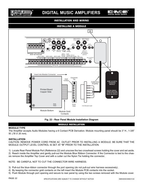
PROFESSIONAL AUDIO & SOUND®TMDIGITAL MUSIC AMPLIFIERSDIGITAL MUSIC SERIESINSTALLATION AND WIRINGINSTALLING A MODULE22RVC CLISTEDCOMMERCIALAUDIOEQUIPMENTUS 30TJEQ LINKPREOUTSUB OUTPRE EQMIXBUSSINPUT-4(AUX1)47kohm 100mV(AUX1)ATTENUATORINPUT-5(AUX2)47kohm 100mVL(AUX2)ATTENUATORWARNING: THIS APPLIANCEMUST BE EARTHEDINPUT 2 (MIC)G COM HOTINEQ LINKOUTINPUT 3 (MIC)G COM HOTPOWERINSUB OUTPOST EQINPUT 4 (MIC)GLINE OUT600INPUT 4REMOTEVOLUMECOM HOT RVC RVCON OFFTONEBYPASSAUX247Kohm 100 mVINPUT5 (MIC-AUX2)G COM HOTTELG COM HOTRINPUT 5MIC-AUX 2BY INTERNALSWITCHTEL OUTPUTLEVEL250ohm 1.5mVBALANCED600 ohm 100mVInsert into Module ConnectorGoldContactConnectorTopCable fromAmplifierPORT ACCEPTSSTANDARDMODULEPrinted BoardCopper SideCAUTION: REMOVEPOWER CORD FROMAC OUTLET PRIOR TOINSTALLING MODULESideViewFrontView3<strong>120</strong> Module InstallModule BottomModule GoldContactsFig. 22 - Rear Panel Module Installation DiagramMODULE INSTALLATIONMODULE TYPEThe Amplifier accepts Audio Modules having a 6 Contact PCB Derivation. Module mounting panel should be 3” H., 1-3/8”W. (78 X 35 mm).INSTALLATIONCAUTION: REMOVE POWER CORD FROM AC OUTLET PRIOR TO INSTALLING A MODULE. BE SURE THAT THEMODULE OUTPUT LEVEL CONTROL IS SET AT “0” PRIOR TO THE INSTALLATION.1) Locate Rear Panel Module Port (Reference 22) and unscrew the two crosshead screws holding the cover and set aside.2) Reach inside the Amplifier and gently pull-out the Module Blue Ribbon Connector. If the Connector is tied to the chassisremove the Amplifier Top Cover and with a cutter cut the Nylon Tie holding the connector.NOTE: BE CAREFUL NOT TO CUT THE CONNECTOR WIRE HARNESS.3) Pull-out the blue-ribbon connector through the port opening (do not pull-out wire harness excessively).4) By keeping the connector gold contacts on the left insert the Module PCB contacts into the socket.5) Push Module through port opening and secure to rear panel by using the two screws removed with the Module cover.PAGE 22 SPECIFICATIONS ARE SUBJECT TO CHANGE WITHOUT NOTICE <strong>DMS3040</strong>/30<strong>80</strong>/3<strong>120</strong>