OM163 DMS3040-80-120 MANUAL.qxd - Paso Sound Products
OM163 DMS3040-80-120 MANUAL.qxd - Paso Sound Products
OM163 DMS3040-80-120 MANUAL.qxd - Paso Sound Products

Create successful ePaper yourself
Turn your PDF publications into a flip-book with our unique Google optimized e-Paper software.
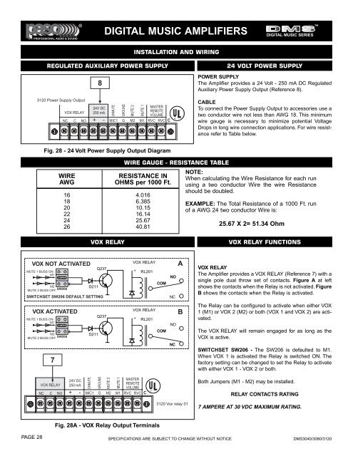
PROFESSIONAL AUDIO & SOUND®TMDIGITAL MUSIC AMPLIFIERSDIGITAL MUSIC SERIESINSTALLATION AND WIRINGREGULATED AUXILIARY POWER SUPPLY3<strong>120</strong> Power Supply OutputVOX RELAY824V DC250 mAUNMUTEGROUNDMUTE 2MUTE 1NC C NO + - MIC1 G M2 M1 RVCMASTERREMOTEVOLUMERVC C24 VOLT POWER SUPPLYPOWER SUPPLYThe Amplifier provides a 24 Volt - 250 mA DC RegulatedAuxiliary Power Supply Output (Reference 8).CABLETo connect the Power Supply Output to accessories use atwo conductor wire not less than AWG 18. This minimumwire gauge is necessary to minimize potential VoltageDrops in long wire connection applications. For wire resistancerefer to Table below.Fig. 28 - 24 Volt Power Supply Output DiagramWIREAWGWIRE GAUGE - RESISTANCE TABLERESISTANCE INOHMS per 1000 Ft.16 4.01618 6.38520 10.1522 16.1424 25.6726 40.81NOTE:When calculating the Wire Resistance for each runusing a two conductor Wire the wire Resistanceshould be doubled.EXAMPLE: The Total Resistance of a 1000 Ft. runof a AWG 24 two conductor Wire is:25.67 X 2= 51.34 OhmVOX RELAYVOX RELAY FUNCTIONSVOX NOT ACTIVATEDMUTE 1 BUSS ONM1JUMPERM2MUTE 2 BUSS OFFSW206D211Q237SWITCHSET SW206 DEFAULT SETTINGXVOX RELAY+ RL201COMNONCAVOX RELAYThe Amplifier provides a VOX RELAY (Reference 7) with asingle pole dual throw set of contacts. Figure A at leftshows the contacts when the Relay is not activated. FigureB shows the contacts when the Relay is activated.VOX ACTIVATEDMUTE 1 BUSS ONM1JUMPERM2MUTE 2 BUSS OFFSW2067XQ237D211VOX RELAY+ RL201COMNONCBThe Relay can be configured to activate when either VOX1 (M1) or VOX 2 (M2) or both (VOX 1 and VOX 2) are activated.The VOX RELAY will remain engaged for as long as theVOX is active.SWITCHSET SW206 - The SW206 is defaulted to M1.When VOX 1 is activated the Relay is switched ON. Thefactory setting can be changed to set the Relay to activatewith either VOX 1 - VOX 2 or both.VOX RELAY24V DC250 mAUNMUTEGROUNDMUTE 2MUTE 1NC C NO + - MIC1 G M2 M1 RVCMASTERREMOTEVOLUMERVC CBoth Jumpers (M1 - M2) may be installed.RELAY CONTACTS RATING3<strong>120</strong> Vox relay 017 AMPERE AT 30 VDC MAXIMUM RATING.Fig. 28A - VOX Relay Output TerminalsPAGE 28 SPECIFICATIONS ARE SUBJECT TO CHANGE WITHOUT NOTICE <strong>DMS3040</strong>/30<strong>80</strong>/3<strong>120</strong>