Improved Circuit Model of Photovoltaic Array - courses.cit.cornell.edu
Improved Circuit Model of Photovoltaic Array - courses.cit.cornell.edu
Improved Circuit Model of Photovoltaic Array - courses.cit.cornell.edu

Create successful ePaper yourself
Turn your PDF publications into a flip-book with our unique Google optimized e-Paper software.
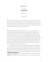
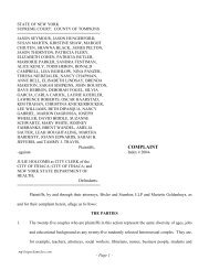
P (W)<br />
60<br />
40<br />
20<br />
1) I = 3.1 A 2) I = 2.6 A 3) I = 2 A<br />
0<br />
0 5 10 15 20 25<br />
V (v)<br />
Fig. 9 P-V family curves with proposed model for different<br />
irradiation levels<br />
B. Classical PV <strong>Model</strong><br />
In addition to the proposed PV model, classical PV model<br />
is also carried out for comparison. Simulation results <strong>of</strong> PV<br />
using classical circuit model are presented in Fig. 10 and Fig.<br />
11.<br />
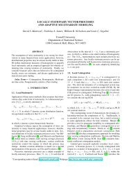
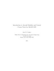
4<br />
I (A)<br />
3<br />
2<br />
1<br />
International Journal <strong>of</strong> Electrical Power and Energy Systems Engineering 2:3 2009<br />
0<br />
0 5 10 15 20 25<br />
V (v)<br />
Fig. 10 I-V curve with classical model<br />
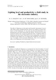
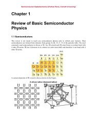
60<br />
50<br />
40<br />
P (W) 30<br />
20<br />
10<br />
0<br />
0 5 10 15 20 25<br />
V (v)<br />
Fig. 11 P-V curve with classical model<br />
According to the obtained results, the proposed model <strong>of</strong>fer<br />
better waveforms for I-V and P-V curves. While classical PV<br />
model produces abrupt change in the slope <strong>of</strong> P-V curve and<br />
I-V curve observed in Fig. 10 and Fig. 11.<br />
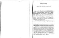
C. Mismatched PV Panels<br />
The proposed PV model is also used to simulate<br />
mismatched PV panels when exposed to different solar<br />
irradiance. In this section two mismatched PV panels<br />
connected in series are simulated. The irradiation levels are<br />
adjusted such that the light generated currents are 3 A and 1<br />
A.<br />
2<br />
1<br />
3<br />
188<br />
The corresponding P-V curve is shown in Fig. 12. It is clear<br />
that the curve exhibits two maxima at two different voltage<br />
levels which is similar to what happens in real operation.<br />
P (W)<br />
60<br />
50<br />
40<br />
30<br />
20<br />
10<br />
0<br />
0 5 10 15 20 25 30 35 40<br />
V (v)<br />
Fig. 12 P-V curve <strong>of</strong> simulated mismatched PV Panels<br />
V. CONCLUSION<br />
This paper presents simplified piecewise linear model for<br />
PV solar panels suitable for power electronics simulation<br />
studies. The proposed circuit model accounts also for the<br />
behaviour <strong>of</strong> mismatched PV panels. The obtained results<br />
prove the validity <strong>of</strong> the proposed model to simulate the PV<br />
with considerable accuracy under different operating<br />
conditions.<br />
REFERENCES<br />
[1] E. V. Solodovnik, S. Liu, and R. A. Dougal, "Power Controller Design<br />
for Maximum Power Tracking in Solar Installations," IEEE Trans.<br />
Power Electron., vol. 19, pp. 1295-1304, Sept. 2004.<br />
[2] Y.T. Tan; et. al.; “A <strong>Model</strong> <strong>of</strong> PV Generation Suitable for stability<br />
analysis ”, IEEE Trans. On energy Conv., Vol. 19, No. 4, 2004.<br />
[3] J. A. Jiang; et. al , “Maximum power tracking for photovoltaic power<br />
systems”, Tamkang Journal <strong>of</strong> Science and Engineering, Vol. 8, No. 2,<br />
pp. 147-153, 2005.<br />
[4] Ryan Campbell , “A circuit-based photovoltaic array model for power<br />
system studies”, Proceedings <strong>of</strong> the 39th North American Power<br />
Symposium (NAPS 2007), Las Cruces, NM, USA, October 2007.<br />
[5] E. Koutroulis; et. al, “Development <strong>of</strong> a Microcontroller-based<br />
photovoltaic maximum power tracking control system”, IEEE Trans. On<br />
power Electronics, Vol. 16, No. 1, pp. 46-54, 2001.<br />
[6] T.Y. Kim, et. al., "A novel maximum power point tracking control for<br />
photovoltaic power system under rapidly changing solar radiation," in<br />
IEEE International Symp. on Ind. Electron., pp. 1011-1014, 2001.