Lab 6: DC Circuits
Lab 6: DC Circuits
Lab 6: DC Circuits

Create successful ePaper yourself
Turn your PDF publications into a flip-book with our unique Google optimized e-Paper software.
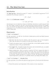
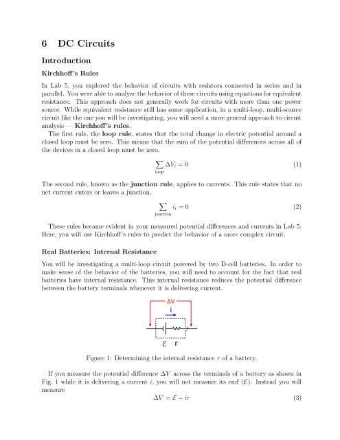
6 <strong>DC</strong> <strong>Circuits</strong>IntroductionKirchhoff’s RulesIn <strong>Lab</strong> 5, you explored the behavior of circuits with resistors connected in series and inparallel. Youwereabletoanalyzethebehaviorofthesecircuitsusingequationsforequivalentresistance. This approach does not generally work for circuits with more than one powersource. While equivalent resistance still has some application, in a multi-loop, multi-sourcecircuit like the one you will be investigating, you will need a more general approach to circuitanalysis — Kirchhoff’s rules.The first rule, the loop rule, states that the total change in electric potential around aclosed loop must be zero. This means that the sum of the potential differences across all ofthe devices in a closed loop must be zero,∑∆V i = 0 (1)loopThe second rule, known as the junction rule, applies to currents. This rule states that nonet current enters or leaves a junction,∑junctioni i = 0 (2)These rules became evident in your measured potential differences and currents in <strong>Lab</strong> 5.Here, you will use Kirchhoff’s rules to predict the behavior of a more complex circuit.Real Batteries: Internal ResistanceYou will be investigating a multi-loop circuit powered by two D-cell batteries. In order tomake sense of the behavior of the batteries, you will need to account for the fact that realbatteries have internal resistance. This internal resistance reduces the potential differencebetween the battery terminals whenever it is delivering current.ΔViErFigure 1: Determining the internal resistance r of a battery.If you measure the potential difference ∆V across the terminals of a battery as shown inFig. 1 while it is delivering a current i, you will not measure its emf (E). Instead you willmeasure∆V = E −ir (3)
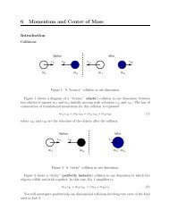
where r is the internal resistance of the battery. When the battery is disconnected from thecircuit, sothati = 0, thenameasurement ofthepotentialdifferenceacrossitsterminalsgivesE. It is therefore possible to calculate the internal resistance of a battery from measurementsof ∆V, i and E usingr = E −∆V(4)iExperiment: a Multi-loop Circuit with Two Power SourcesBCR 2R 1i 2Di 1E 1r 1r 2i 3R 3E 2AFigure 2: A multi-loop <strong>DC</strong> circuit with two power sources and three resistors.YouhavebeensuppliedwithtwoD-cellbatteriesinholders, asetofthreeresistorsmountedon a Plexiglas stand, a digital multimeter (DMM), and several leads for connecting thesecomponents.1. Turn the knob on the DMM to measure resistance on the hundreds of Ω scale. Measureand record the resistance of each resistor with the DMM by connecting one end of tothe V/Ω terminal and the other end to the COM terminal. Check your results with thecolor codes.2. Measure andrecord theemfs(E values) ofyour batteries. It is important not to connectthem to anything other than the DMM when you make these measurements. (Why?)3. Construct the circuit shown in Figure 2. Make sure that the batteries’ orientations arecorrect and that you record which E value goes with which battery.4. Turn the knob on the DMM to measure potential difference on a scale of a few Volts.Measure the potential difference ∆V BA = V B −V A between the points labeled A and Bin Fig. 2 by connecting the V/Ω terminal of the DMM to point B and the COM terminalof the DMM to point A. Similarly measure ∆V CB , ∆V CA , ∆V <strong>DC</strong> , and ∆V DA .5. Use the DMM to measure magnitudes and directions the three unique currents in thecircuit i, i 1 , and i 2 . This will require you to connect the DMM in series with eachseparate branch of the circuit. Remember never to connect an ammeter in parallelwith anything! Use the red current terminal on your DMM best suited to measure mA
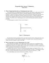
currents. Be careful not to change the way the circuit is arranged as you make thesemeasurements. If you’re not sure how, ask for help!In order to determine the direction of the current, remember that a positive currentflows into the red A (or mA) terminal and out of the black COM terminal. The directionsyou measure may not agree with the arrows in Figure 2, and that’s OK! Record whatyou actually observe.6. Check your measurements by using your measured currents and voltages ∆V CB , ∆V <strong>DC</strong> ,and ∆V CA along with Ohm’s Law to calculate the resistances R 1 , R 2 , and R 3 . Comparethem with the actual values measured with the DMM in step 1. Resolve anyinconsistencies before you move on!Analysis1. Use Eq. 4 and your measurements of ∆V BA and i 1 to find the internal resistance r 1 ofbattery 1. Similarly, use ∆V DA and i 2 to find r 2 .R 2R 1i 2i 1E 1i 3R 3E 2Figure 3: Simplified circuit diagram.2. UseKirchhoff’srulesandyourmeasuredresistancesandemfstopredictthemagnitudesanddirectionsofeachoftheunique currentsi 1 , i 2 , andi 3 . Itsimplifies themathematicssomewhat to combine the pairs of resistors connected in series R ′ 1 = R 1 + r 1 andR ′ 2 = R 2 +r 2 as illustrated in Fig. 3.Questions1. Why was it important to measure the emfs (E values) of your batteries while they werenot connected to anything other than the DMM?2. What are the internal resistances of your batteries? Show your calculations.3. Are your measured potential differences compatible with the loop rule?4. Showthecalculations youmade topredict thecurrents inthecircuit shown inFigure2.Compare your predictions to your measurements, and discuss any significant (> 5%)discrepancies.