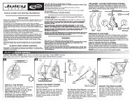
2006 - Monster
2006 - Monster
2006 - Monster
- No tags were found...

You also want an ePaper? Increase the reach of your titles
YUMPU automatically turns print PDFs into web optimized ePapers that Google loves.
© Marzocchi Suspension<strong>2006</strong> - <strong>Monster</strong><strong>2006</strong> - <strong>Monster</strong>Technical instructions
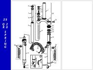
© Marzocchi Suspension<strong>2006</strong> - <strong>Monster</strong>Exploded view - <strong>Monster</strong>Rif. Code Quantity1 850332>A 12 528050 23 850333 14 717069/R 15 701218/C 16 520023PN 47 5031609LUCI 18 547702 19 538028>B 210 507657 211 523232 212 528005 213 717068/R 114 309683CH/R 115 5321103 216 528223 417 521142IW>A 219 5181239CH/R 120 5141159 225 518057 226 528144 227 701206/C 128 520264AC 129 520324 230 520048 832 501493LA 133 505059LA>A 134 505056LA 135 520308PN 936 526127KR/C 137 524163 138 309683CH/K/R 139 533281 240 523243 241 528053>A 242 522226AA 243 538035>D2 244 850691 145 5181240CH/R 146 5321119LA 147 520279QF 648 850755/C 149 5031651/C 150 5321143 151 517030 251 517076 251 517029 251 517057 251 517028 252 530089>B 253 517044 254 5141087 255 521171 256 521189 158 517080 158 517082 159 530097>B 161 517044 262 5321181/R 263 530090>B 164 521190 166 517074 166 517057 166 517028 167 5141087 268 535099 169 5321018 170 508983>B/R 171 502531LA 172 7051133 173 531067 2<strong>Monster</strong> - Oil levelsPosition Oil type Quantity (cc)Right fork leg SAE 7,5 - 550013 430Left fork leg SAE 7,5 - 550013 430
© Marzocchi Suspension<strong>2006</strong> - <strong>Monster</strong>Spare part list - <strong>Monster</strong>Rif. Code DescriptionQ.ty in themodel1 850332>A SCREW + PIN 12 528050 O-RING 23 850333 SCREW UNIT 14 717069/R R.H VALVE UNIT 15 701218/C COMPRESSION PLUG UNIT 16 520023PN SCREW TCE M6X20 47 5031609LUCI RH SLIDER 18 547702 RH+LH MONSTER '06 LABELS-BLK 19 538028>B LOWER BUSH 210 507657 STANCHION TUBE 211 523232 O-RING 212 528005 O-RING 2081 213 717068/R L.H VALVE UNIT 114 309683CH/R R.H PUMPING ROD 115 5321103 INNER ROD 216 528223 O-RING 417 521142IW>A NUT 219 5181239CH/R R.H BODY 120 5141159 SPRING 225 518057 PRELOAD SLEEVE 226 528144 O-RING 227 701206/C REBOUND PLUG UNIT 128 520264AC IN CAP AXLE 129 520324 SCREW 230 520048 SCREW 832 501493LA UPPER CROWN 133 505059LA>A LOWER HANDLEBAR CLAMP 134 505056LA UPPER HANDLEBAR CLAMP 135 520308PN SCREW 936 526127KR/C HANDLEBAR SHIM SHIVER 137 524163 PISTON RING 138 309683CH/K/R L.H PUMPING ROD 139 533281 DUST SEAL DIA.40 240 523243 STOP RING 241 528053>A OIL SEAL DIA.40 242 522226AA CAP 243 538035>D2 UPPER PILOT BOSS 244 850691 MTB MONSTER T OIL SEALS KIT 145 5181240CH/R L.H BODY 146 5321119LA ARCH 147 520279QF SCREW 648 850755/C AXLE 149 5031651/C LH SLIDER + SPACERS 150 5321143 VALVE 151 517030 COMPRESSION DAMPING WASHER 251 517076 COMPRESSION DAMPING WASHER 251 517029 COMPRESSION DAMPING WASHERS 251 517057 SHIM 21X8.1X0.2 2
© Marzocchi Suspension<strong>2006</strong> - <strong>Monster</strong>51 517028 SHIM 23X8.1X0.2 252 530089>B PISTON 253 517044 SHIM 23X8.1X0.3 254 5141087 REBOUND SPRING 255 521171 NUT 256 521189 NUT 158 517080 SHIM 15X8.1X0.1 158 517082 SHIM 23X8.1X0.1 159 530097>B PISTON 161 517044 SHIM 23X8.1X0.3 262 5321181/R ROD 263 530090>B PISTON 164 521190 NUT 166 517074 REED VALVE 166 517057 SHIM 21X8.1X0.2 166 517028 SHIM 23X8.1X0.2 167 5141087 REBOUND SPRING 268 535099 PISTON CUP 169 5321018 VALVE 170 508983>B/R ALLOY STEER TUBE DIA.30 171 502531LA LOWER CROWN 172 7051133 CROWN+ ALLOY STEM 173 531067 BUFFER 2
© Marzocchi Suspension<strong>2006</strong> - <strong>Monster</strong>Technical characteristics: Technical characteristicsDual-crown fork with ø 40mm legs.Available travels: 200 mm.Right fork leg damping element: spring.Left fork leg damping element: spring.Right fork leg damping system: HSCV cartridge with external adjustment of rebound and compression.Left fork leg damping system: HSCV cartridge with external compression adjustment at travel end (High Speed Compression).The stanchion tubes are joined with screws to the steering crown.The guide of the stanchion tubes inside the sliders has special long-life bushes that are easy to reach.Lubrication and cooling of the parts subject to friction with a specially formulated oil.Steer tube: aluminium, 1-1/8", threadless.Crown: BAM® aluminium alloy forged and CNC machined.Top crown: aluminium alloy forged and CNC machined.Stanchions: anodised aluminium.Sliders: aluminium alloy, CNC machined.Arch: aluminium alloy, CNC machined, to improve the structural stiffness of the fork.Sliding bushings: made of friction-free and wear-free material.Springs: constant pitch.Seals: computer designed oil seals that guarantee maximum seal in any condition.Oil: specially formulated oil that prevents foam and keeps the viscosity unchanged while offering high performance; free from static friction.Dropout type: motorcycle type wheel axle support, with 20mm advanced axle and double screw locking system on both dropouts (specific wheelaxle, supplied).Disk brake mount: DH International Standard for post-mount 8" disk.Max wheel size: 3.0" x 26".Handlebar with direct clamp on top crown: available as option.
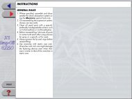
© Marzocchi Suspension<strong>2006</strong> - <strong>Monster</strong>Warnings: Instructions for useMARZOCCHI forks are based on an advanced technology coming from the company’s years long experience in the professional mountain bikeindustry.For the best results, we recommend inspecting and cleaning the area below the dust seal and the stanchion tube after every use and lubricating theparts with some silicone oil.MARZOCCHI forks usually offer the best performances since the very first rides. Notwithstanding this, a short running-in period may be necessary(5-10 hours) to adjust the internal couplings. This precaution will lengthen your fork’s life and guarantee its best performances.We recommend changing the oil at least every 100 hours.The forks with a polished finish must be treated periodically with polishing paste to keep the exterior shining like new.Warnings: General safety rulesAfter disassembling the forks, always use new, original Marzocchi seals when reassembling.To tighten two bolts or nuts that are near each other, always follow the sequence 1-2-1, and tighten to the required tightening torque.Before reassembly, wash all new and old components and dry them with some compressed air, making sure there are neither breaks nor burrs.Never use flammable or corrosive solvents when cleaning the forks, as these could damage the fork’s seals. If you must use a solvent, usebiodegradable detergents that are not corrosive, non-flammable, or have a high flash point.Before reassembling, always lubricate those components that are in contact with the fork’s oil.If you are planning not to use your forks for a long period of time, always lubricate those components that are in contact with the fork’s oil.Always collect and keep any lubricants, solvents, or detergents, which are not completely biodegradable in the environment. These materials shouldbe kept in appropriate containers, and disposed of according to local laws.Always grease the seal lips before reassembling.All of the components of Marzocchi forks require the use of metric tools. Use only metric tools. Imperial (US) tools may have similar sizes, but candamage the bolts, making them impossible to loosen or tighten.When using a screwdriver to assemble or disassemble metal stop rings, O-rings, sliding bushings, or seal segments, avoid scratching or cutting thecomponents with the screwdriver tip.Do not carry out any maintenance and / or adjustment operations that are not explained in this manual.Only use original Marzocchi spare parts.Before servicing the fork, we recommend washing the fork thoroughly.Work in a clean, organized, and well-lit place. If possible, avoid servicing your forks outdoors.Carefully check to see that your work area is free of dust and metal shavings from any component of the forks.Never modify your fork in any way.We recommend overhauling one fork leg at a time.Warnings: Fitting the fork onto the frameThe fork is supplied with “A-Head Set” steer tube to be cut to size according to frame being used.Fitting the fork onto the bike frame is a very delicate operation that must be carried out at one of our service centres only.The assembling on the frame and the adjustment of the steer tube must be carried out following the instructions of the steering set manufacturer.A wrong installation can be dangerous for the rider.Marzocchi does not guarantee the assembly and accepts no liability for damage and/or accidents arising from a wronginstallation.The steer tube must be pressed into the crown; its replacement must be carried out by one of our service centres using the adequate tools.A wrong installation of the steer tube into the crown may cause the rider to lose the control of the bike and lead to seriouspersonal injury.For a correct installation of the fork onto the frame, check that:with the fork legs at travel end, the distance "D" between the bottom face of the crown and the dust sealis higher than 3 mm.The clamping of the stanchions to the crowns shall be done in the areas with the large diameter.Fix the stanchions to the crowns so that the bottom face of the crown is slightly above the reference notch on the stanchion.The clamping of the stanchions to the crowns must be done only in the areas with larger diameter (darkerarea in the picture).
© Marzocchi Suspension<strong>2006</strong> - <strong>Monster</strong>For a correct installation of the fork onto the frame,check that distance H, corresponding to the length ofthe steer tube between the two crowns, is less than 190 mm.With the fork legs at travel end, the distance between the inflated tire and the bottom of the crown must be at least 4 mm.A different position of the crowns can result in damage to the fork and in serious personal injury.For a correct installation of the fork onto the frame, proceed as follows:With the fork legs at travel end, the distance "D" between the bottom face of the crown and the dust sealshall be higher than 3 mm.The clamping of the stanchions to the crowns shall be done in the areas with the large diameter.Install the fork without top steering crown onto the frame already equipped with steering set.Mount the top steering crown onto the stanchions and the steer tube.If the legs come out too much, put some shims (G) onto the crown, in correspondence of the steer tube,taking into account that distance "H" shall be less than 190 mm.Two different top crowns are available to adapt the fork to frames with longer or shortersteer tube seat.
© Marzocchi Suspension<strong>2006</strong> - <strong>Monster</strong>If the position of the crown with respect to the sliders has been changed, restore the original distance"D".After tuning the steering set, tighten the screws (L) onto the top crown to the recommended tighteningtorque (10 Nm ± 1).Over-tightening the screws (L) can deform the tubes and weaken the structure.Tighten screw (R) of the steer tube to the recommended tightening torque (10 Nm ± 1).Warnings: Installing the disk brakeInstalling the brake system is a delicate and critical operation that must be carried out by an authorized Marzocchi Service Center.Marzocchi is not responsible for the installation and accepts no liability for damage and/or accidents arising from this operation.Improper installation of a disk brake system can overstress the caliper mountings, which may cause the caliper mountings to break, resulting in lossof control of the bicycle, an accident, personal injury, or death. Be sure that the brake system installation is also performed in strict compliance withthe instructions provided by the brake system manufacturer.Improper installation can result in an accident, personal injury, or death.Use only brake systems that comply with the forks specifications.The brake cable must never touch the crown and stanchions.
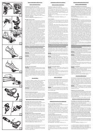
© Marzocchi Suspension<strong>2006</strong> - <strong>Monster</strong>Warnings: Assembling the wheel on forks with ø20mm through-axleFor a correct operation of the fork, install the wheel as explained below:If the fork has been dismantled from the bike frame or the position of the fork legs with respect to thesteering crowns has been changed, loosen the 6 screws (1) fixing arch (2) with a 4mm Allen wrench.Insert the wheel axle (3) through the right dropout, the wheel and the left dropout.With the 6mm Allen wrench, tighten the left wheel axle screw (4) to the recommended tightening torque(15 ± 1 Nm).Check the correct fork-wheel alignment by fully compressing the fork a few times. The wheel should notcome into contact with any parts of the fork.Lift the front wheel above the ground; turn the wheel a few times to verify the correct alignment and thedistance from the disk brake. Read the instructions of the brake system manufacturer for the correctspecifications.With a 5mm Allen wrench, tighten screws (5) on both dropouts to the recommended tightening torque(10 Nm ± 1) following the sequence 1-2-1.Using a 4mm Allen wrench, tighten screws (1) to the recommended tightening torque (6 Nm ± 1)following the sequence 1-2-3-2-1.
© Marzocchi Suspension<strong>2006</strong> - <strong>Monster</strong>Warnings: Installing the handlebar mountFor a correct installation of the handlebar mount, follow the instructions below:Install the bottom handlebar mount (1) onto the top crown so that the fixing holes match.With a 5mm Allen wrench, lock the handlebar mount tightening screws (2) to the recommendedtightening torque (10 Nm ±1).Fit the handlebar right in the middle of the mount.Lock the handlebar in position with the special U-bolt (3).With a 5mm Allen wrench, tighten screws (4) to the recommended tightening torque (10 Nm ±1).On request, special adapters (5) are available to install handlebars with a different diameter.
© Marzocchi Suspension<strong>2006</strong> - <strong>Monster</strong>Dismantling: Removing the top capsPut the fork in the vice in vertical position, fixing it by the dropouts.Put the fork in the vice in a vertical position, fixing it by the dropouts.Fully unscrew lock cap (1), using a 28mm socket spanner.Slowly lower the stanchions on the sliders.Push spring (2) and the preload tube (3) downwards so you can reach locknut (5) with the 10mmspanner.Holding locknut (5) with the 10mm spanner, use the 28mm spanner to unscrew the fork cap (1).Dismantling: Draining the oilRemove the fork legs from the steering crowns.Remove the fork legs from the steering crowns.Remove the preload tube (1) and spring (2) from both fork legs.Free the fork from the vice and tip it into a container of a suitable size to drain the oil; compress the forka few times to help the oil flow out.Do not pour used oils on the ground.Dismantling: Dismantling the hydraulic cartridge
© Marzocchi Suspension<strong>2006</strong> - <strong>Monster</strong>This operation must be done only after having drained all of the oil out of the slider.Proceed as follows for both fork legs:Turn the fork leg upside down and with an 8mm Allen wrench loosen the bottom screw (10).Remove the bottom screw (10) complete with O-ring (9).Pull the complete cartridge (5) off the fork leg.This procedure shows how to fully overhaul the hydraulic cartridge; do these operations onlyif necessary.With a 10mm fixed spanner fully unscrew locknut (6).Push the bottom valve into the cartridge.Remove the metal stop ring (14) from the bottom of the cartridge.Push the rod of the pumping element downwards and remove the complete bottom valve (8).Pull the piston rod (12) off the liner (13).
© Marzocchi Suspension<strong>2006</strong> - <strong>Monster</strong>Overhauling the right bottom valveBlock the valve body (8).With a 13mm spanner loosen nut (20).Remove in this order: nut (20), spring (21), washer (22), the piston complete with O-ring (23), and thecompression adjusting washer or stack of washers (24).Replace the piston O-ring, if necessary.Washers (24) and piston (23) determine the compression damping. To change the fork behaviour youcan replace such components.Use only MARZOCCHI genuine washers and pistons.To reassemble the bottom valve, proceed in reverse order.The nut (20) shall be tightened to 6 Nm; over-tightening nut (20) can weaken the structure.Overhauling the right pumping elementHold the rod of the pumping element through the wrench mount (12).With a 12mm spanner loosen nut (25).Remove in this order: nut (25), the rebound adjusting washer or stack of washers (26), the pistoncomplete with segment (27), washer (28) and spring (29).Replace the piston segment, if necessary.Washers (26) and piston (27) determine the rebound damping. To change the fork behaviour you canreplace such components.Use only MARZOCCHI genuine washers and pistons.To reassemble the pumping element, proceed in reverse order.The nut (25) shall be tightened to 6 Nm; over-tightening nut (25) can weaken the structure.
© Marzocchi Suspension<strong>2006</strong> - <strong>Monster</strong>Overhauling the left bottom valveBlock the valve body (8).With a 13mm spanner loosen nut (20).Remove in this order: nut (20), spring (21), washer (22), the piston complete with O-ring (23), and thestack of washers (24).Replace the piston O-ring, if necessary.Washers (24) and piston (23) are not adjusting elements.To reassemble the bottom valve, proceed in reverse order.The nut (20) shall be tightened to 6 Nm; over-tightening nut (20) can weaken the structure.Overhauling the left pumping elementHold the rod of the pumping element through the wrench mount (12).With a 12mm spanner loosen nut (25).Remove in this order: nut (30), spring (31), washer (32), piston (33), the washer or stack of washersadjusting the compression at travel end (34) and the spring cup (35).Washers (34) and piston (33) determine the compression damping at travel end. To change the forkbehaviour you can replace such components.Use only MARZOCCHI genuine washers and pistons.To reassemble the pumping element, proceed in reverse order.The nut (25) shall be tightened to 6 Nm; over-tightening nut (25) can weaken the structure.
© Marzocchi Suspension<strong>2006</strong> - <strong>Monster</strong>Dismantling: Breaking down stanchion tube, slider and removing the sealing ringsThis operation must be done only after having drained all of the oil out of the slider.Proceed as follows for both legs:Remove the dust seal (1) from its seat using a small flat-tip screwdriver.With the same screwdriver remove the metal stop ring (2).Pull stanchion (3) out of slider (4); to separate these two elements you will have to pull hard. With thisoperation the sealing ring (5), the spring cup (6) and the top guide bush (7) will be removed from theslider.Remove the bottom guide bush (8) by hand. If this operation is difficult by hand, use a flat-tip screwdriverin the bush groove.Remove the top guide bush (7), the spring cup (6), the sealing ring (5), the stop ring (2) and the dustseal (1) from the stanchion.The old sealing rings and the dust seals must not be used again.
© Marzocchi Suspension<strong>2006</strong> - <strong>Monster</strong>
© Marzocchi Suspension<strong>2006</strong> - <strong>Monster</strong>Assembling: Reassembling stanchion tube, slider and sealing ringsThe old sealing rings and dust seals must not be used again.Before reassembling, check the conditions of the guide bushes. Replace, if they are scratched or grooved. Check the wearproofcoating of the guide bushes which must be in a good condition.The old sealing rings and dust seals must not be re-used.Beforere assembling, check the conditions of the guide bushes: replace them if they arescratched or grooved. Check the wearproof coating of the guide bushes which must be in agood condition.Smear the dust seal and the sealing ring with some grease.Insert the following components in the stanchion tube in this order: top guide bush (7), spring cup (6),sealing ring (5), stop ring (2) and dust seal (1).Insert the bottom guide bush (8) by hand.If this operation is difficult by hand, use a flat-tip screwdriver in the bush groove.Delicately introduce the stanchion into the slider, being very careful not to damage the bottom guidebush.Guide the top guide bush until it comes in contact with the slider, the spring cup and the sealing ring.Mount the introducer (A) on the stanchion and use this, by pushing on sealing ring (5), to insert the topguide bush, the spring cup and the sealing ring.Using a small flat-tip screwdriver, fit stop ring (2) and check that it fits perfectly into its groove.Take great care not to damage the internal surfaces of the slider when fitting the stop ring.Insert the dust seal (1) in its seat using the special inserting tool (A).
© Marzocchi Suspension<strong>2006</strong> - <strong>Monster</strong>Assembling:During the assembly of the pumping unit, strictly obey the instructions below.Do not, at any times, reverse the position of the pumping elements in the fork legs (if you are unsure about anything, please referto the relevant exploded view).Assembling: Assembling the cartridgeProceed as follows for both legs:Insert the piston rod (12) in liner (13).Insert the complete bottom valve (8) in its seat.Mount the stop ring (14) using a small screwdriver and check it fits perfectly into its groove.Push the pumping element rod downwards and rest the bottom valve down; check that the stop ring (14)does not come out of its seat.Screw down locknut (6) without tightening.
© Marzocchi Suspension<strong>2006</strong> - <strong>Monster</strong>Insert the complete cartridge (5) into the stanchion.With an 8mm Allen wrench, tighten the bottom screw (10) complete with O-ring (9) to the recommendedtightening torque (25 Nm ± 1).In the screw of the right fork leg there is a small pin to adjust the compression; if necessary,tighten this pin down with a flat-tip screwdriver.Assembling: Filling with oilBlock the fork in the vice in perfectly vertical position.Fully lower the stanchion tubes.In a graduated recipient, prepare the quantity of oil to pour into the fork leg (see table).Pour roughly 1/3 of the oil required into each stanchion, then pump the fork a few times to eliminate anytraces of air.Pour the rest of oil in.
© Marzocchi Suspension<strong>2006</strong> - <strong>Monster</strong>A lower or higher volume or a type of oil other than the one recommended can change the behaviour of the fork in every phase.Fully lift the stanchion tubes.Insert spring (2) and the preload tube (1) in both legs.Assembling: Mounting the top capsPut the fork in the vice in vertical position, fixing it by the dropouts.Put the fork in the vice in vertical position, fixing it by the dropouts.Check that locknut (5) is fully screwed on the pumping element rod.Check that the adjusting rod (6) is tight.
© Marzocchi Suspension<strong>2006</strong> - <strong>Monster</strong>Screw lock cap (1) down on the cartridge rod without tightening being very careful not to damage the O-ring.With the 10mm and 28mm spanners, tighten locknut (5) on cap (1) to the recommended tighteningtorque (6 Nm ± 1).Lift the stanchion.Screw down lock cap (1).With the 28mm socket spanner, tighten lock cap (1) to the recommended tightening torque (10 Nm ±1).
© Marzocchi Suspension<strong>2006</strong> - <strong>Monster</strong>Setting: General rules for calibrationBy carefully calibrating the damping system you can get the maximum performance out of the same.This paragraph indicates the sequence of operations to perform to set up the Marzocchi forks correctly.In order to find the best settings for you, you will need to try several times to understand where and how to make adjustments. When doing so,please ride in an open area, free from traffic, obstacles and other hazards.The optimal setting is influenced by the geometry of the frame of the mountain bike, the weight of the cyclist, the type of terrain the bike will beused on and the type of obstacles you have to deal with, but also by subjective factors associated with your riding style; therefore it is impossible toprovide objective data on the desired settings.Nevertheless by carefully following the instructions below you will soon be able to find the optimal setting for you.The shock absorber must be calibrated simply by using one adjuster at a time, following the order explained, noting the operations and any resultstep-by-step.During setting don't force the adjusters beyond their limit of travel and don't exceed the max recommended air pressure.To keep the pressure inside the fork’s legs, only use the special MARZOCCHI pump with pressure gauge.The use of any other pump can compromise the inflating operation and cause malfunction or damage to the fork, resulting in anaccident, personal injury or death.Once the correct setting has been found, we recommend noting the number of clicks or turns of the adjuster with respect to the "fully closed"position (adjuster fully clockwise) for a faster re-setting of your fork in case of need.Setting: SAGSAG means the fork bottoming under the biker's weight.How to measure the SAG:Follow these simple steps to measure the SAG.On the leg portion of the fork, measure the distance between the lower crown and the dust seal (seePicture A). Note this value as “H1”.While sitting on the bike, repeat the measurement (see picture B). Note this value as “H2".SAG = H1 - H2How to find the best percent SAG:The best percent SAG is 15-20% for Cross-country and All Mountain forks and 25-30% for Freeride andDownhill forks.In order to calculate the best SAG for your own fork, you will need to make the following calculation:SAG = T x S (T = total travel; S = suggested sinking percentage).Setting: Rebound adjustmentRight fork leg:With the rebound adjuster you can control the return speed of the fork after compression.The right rebound speed setting makes the bike stable letting it follow the variations in the terrain and any obstacles.If the fork setting is too reactive this will make the rear suspension instable and the mountain bike will have a tendency to snake. A too slow settinghowever will cause problems when dealing with multiple obstacles where the suspension can't return to its fully extended position fast enoughbetween one obstacle and the next.Turning adjuster (A) clockwise increases the hydraulic damping making the fork slower during therebound phase.Turning adjuster (A) counter-clockwise decreases the hydraulic damping making the fork more reactiveduring the rebound phase.
© Marzocchi Suspension<strong>2006</strong> - <strong>Monster</strong>Do not force the adjuster beyond its limit of travel.Setting: Compression adjustmentRight fork leg:With the compression adjuster you can control the compression speed.The compression setting is at the user's discretion and must be set to prevent the suspension bottoming out.A "hard" compression setting gives you more stability and lets you ride more aggressively making the mountain bike more reactive, vice versa a"soft" setting means less stability but also a less "nervous" ride.Turning adjuster (A) clockwise increases the hydraulic braking during compression and, under the sameload conditions, reduces the fork travel.Turning adjuster (A) counter-clockwise decreases the hydraulic compression damping making the forkmore reactive on harsh grounds.Do not force the adjuster beyond its limit of travel.Setting: Compression adjustment at travel endLeft fork leg:With the compression adjuster you can control the compression speed.The compression setting is at the user's discretion and must be set to prevent the suspension bottoming out.A "hard" compression setting gives you more stability and lets you ride more aggressively making the mountain bike more reactive, vice versa a"soft" setting means less stability but also a less "nervous" ride.Turning adjuster (A) clockwise increases the hydraulic compression damping at travel end.Turning adjuster (A) counter-clockwise decreases the hydraulic compression damping at travel end.Do not force the adjuster beyond its limit of travel.
© Marzocchi Suspension<strong>2006</strong> - <strong>Monster</strong>Tightening torquesComponentsTightening torque (Nm)Air bleed screw 2±0,5Arch screw 6±1Bottom crown fixing screws 10±1Cap locknut 6±1Cartridge bottom screw 25±1Fork leg top caps 10±1Handlebar fixing screws 10±1Top crown fixing screws 10±1Wheel axle Allen screws 10±1Wheel axle screws 15±1<strong>Monster</strong> - Oil levelsPosition Oil type Quantity (cc)Right fork leg SAE 7,5 - 550013 430Left fork leg SAE 7,5 - 550013 430
© Marzocchi Suspension<strong>2006</strong> - <strong>Monster</strong>DiagnosticsFinding the problem Finding the possible cause Possible solutions proposedFork doesn't get full travel Oil level too high Check oil levelsFork doesn't get full travel Spring rate too stiff Change to softer spring rateFork extends too quickly; harsh top-out afterimpactsFork extends too quickly; harsh top-out afterimpactsRebound damping is not enoughRebound damping is not enoughIncrease rebound dampingFork has too much sag Oil is too fluid Check oil levelsReplace the oil (SAE 7.5) with one of higherviscosity indexFork has too much sag Spring rate too soft Change to stiffer spring rateFork has too much sag Spring rate too soft Increase spring preloadFork has too much sagFork is “sticky”; fork does not perform as newFork is too soft, but the sag is the onerecommendedFork is too soft, but the sag is the onerecommendedFork is too soft, needs more than the maximumpreloadFork is too soft, needs more than the maximumpreloadFork stays down or "packs up" during multipleimpactsFront wheel tends to tuck under while turning leftor rightFront wheel tends to tuck under while turning leftor rightHeavy amount of oil on stanchions; oil drippingdown legsHeavy amount of oil on stanchions; oil drippingdown legsKnocking sound during rebound, but no harsh topoutSpring rate too softDirty sealing rings; fork needs to beservicedCompression damping is not enoughCompression damping is not enoughOil is too fluidSpring rate too softRebound damping is too highRebound damping is too highSpring rate too softSealing rings damagedThe stanchion tubes could be damagedRebound damping is too highIncrease spring preload by replacing the preloadtubeRenew all sealsIncrease compression damping by changing oilvolumesIncrease compression damping with the relevantregisterCheck oil levelsChange to stiffer spring rateDecrease rebound damping with the relevantregisterDecrease rebound damping with the relevantregisterChange to stiffer spring rateRenew all sealsLoss of sensitivity Old oil Change the oilHave the stanchions be checkedDecrease rebound damping with the relevantregisterLoss of sensitivity Sliding bushes worn Renew the sliding bushesOil leaking from the bottom of the fork leg Bottom nut/screw loose Tighten the nut or screwOil ring on stanchions Sealing rings dirty Renew all seals