You also want an ePaper? Increase the reach of your titles
YUMPU automatically turns print PDFs into web optimized ePapers that Google loves.
For exploded diagram and part number information, refer to the Spare Parts Catalog available on our website atwww.rockshox.com.2003-2004 PILOT <strong>SL</strong> & <strong>XC</strong> SERVICE GUIDEContact your local distributor or visit the RockShox website at www.rockshox.com for ordering information.Information contained in this publication is subject to change at anytime without prior notice.For the latest technical information, visit our website at www.rockshox.com.Names used in this manual may be trademarks or registered trademarks of others.© SRAM Corporation • September 2003 PN 95.4308.628.000, Rev. B
2003-2004 <strong>Pilot</strong> <strong>SL</strong> & <strong>XC</strong> <strong>Service</strong> GuideT OOLS N EEDED• Safety Glasses• 24mm 6-point Socket• Plastic Faced Mallet• Biodegradable Solvent• RockShox 5 wt. Oil• Shock Pump• 5mm Hex W rench• 12" long, 1 ¼" diameter soft bristle bottle brush• Long, cylindrical rod•Torque W renchAfter every 100 hours of riding, or less depending on riding conditions and riding style, the following service should be performed.R EMOVE S PRING S TACK1HINT: RIGHT AND LEFT IS DETERMINED FROM THE RIDER’S PERSPECTIVE.1. Remove the air cap from the left side of the fork (fig. 1). Depress theschrader valve and remove the air from the Air Assist chamber.2. <strong>Pilot</strong> <strong>SL</strong> Only: Gently pull to remove the rebound adjuster knob from theright shaft bolt (fig. 2) (external rebound adjuster knob kit11.4304.960.000).3. Loosen shaft bolts five turns (fig. 3A) and tap firmly with a plastic facedmallet to separate the shafts from the lower tubes (fig. 3B). Remove theshaft bolts completely.4. Carefully slide the lower leg assembly off of the upper tubes (fig. 4). Keepa oil pan below the fork to catch the oil. Inspect the condition of removedoil. If the oil is opaque and/or milky (water contamination), the lower tubeassembly should be cleaned.23a3b24 © SRAM Corporation • 2003-2004 PILOT <strong>SL</strong> & <strong>XC</strong> SERVICE GUIDE
2003-2004 <strong>Pilot</strong> <strong>SL</strong> & <strong>XC</strong> <strong>Service</strong> GuideL OWER L EG R EMOVAL5. Spray isopropyl alcohol or a biodegradable solvent (Simple Green, Pedros,or equivalent) down into the lower leg assembly. Using a 12" long, 1 ¼"diameter soft bristle bottle brush to clean the lower tube internals. Drythoroughly.46. Using a 24mm socket wrench (fig. 6), remove the top caps (part numbers:11.4306.206.000 for non-adjust and 11.4306.446.001 for air assist side).67. Remove the spring guide and coil spring (fig. 7) from the left side of thefork (coil spring/spacer kit 11.4306.208.000).7PN 95.4308.628.000, REV. B 25
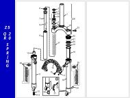
2003-2004 <strong>Pilot</strong> <strong>SL</strong> & <strong>XC</strong> <strong>Service</strong> GuideR EMOVAL OF D AMPER AND P LUNGER S HAFT8. Using a long cylindrical rod, push the air assist plunger up through the uppertube until the lower spring guide protrudes from the crown (Air Assist PlungerAssembly Kit 11.4306.207.000). Unthread the spring guide/plunger assemblyuntil the o-ring has passed the top cap threads (Fig. 8a).NOTE: INSPECT O-RING AND REPLACE IF WORN OR DAMAGED (FIG. 8B). IFYOUR FORK HAS A U-CUP SEAL, REPLACE WITH AN O-RING AIR SEAL(11.4307.208.010). GREASE THE O-RING BEFORE INSTALLATION.8a8b9. Using the long cylindrical rod, push the damper assembly through and outthe top of the upper tubes.NOTE: USE CARE NOT TO DAMAGE THE PISTON GLIDE RING!9A LL T RAVEL S PACER C ONFIGURATION10. Note the all travel spacer on the plunger and damper assembly. For 100 mmof travel, remove the all travel spacer from the damper shaft. Move the alltravel spacer on the plunger assembly so that it sits between the spring andthe plunger (see fig. 10).All TravelSpacerAll TravelSpacer1080 mm Damperand Plunger Assembly100 mm Damperand Plunger Assembly26 © SRAM Corporation • 2003-2004 PILOT <strong>SL</strong> & <strong>XC</strong> SERVICE GUIDE
2003-2004 <strong>Pilot</strong> <strong>SL</strong> & <strong>XC</strong> <strong>Service</strong> GuideD AMPER AND P LUNGER S HAFT I NSTALLATION11. Install the damper assembly (right leg) and plunger assembly (left leg) backthrough the top of the upper tubes.12. Reinstall the spring assembly (with spring guide) into the left side. Installthe air assist top cap lightly by hand (fig. 7).30 cc 5 wt. oil14L OWER T UBE I NSTALLATION13. Slide the lower tube assembly onto the upper tube assembly until you feelthe lower bushing engages with the bottom of the upper tube (fig. 4).IMPORTANT: ENSURE THE GREY DUST SEALS ARE PROPERLY SEATED INTHE LOWER LEGS AND NOT ROLLED OVER ON THE UPPER TUBE.R EFILL F LUIDS14. Invert the fork and fill the left leg (air assist spring side) with 30 ccRockShox 5 wt. oil (fig. 14).15. Slide the lower tubes completely onto the upper tubes until both shafts fullyengage the lower tubes.16. Inspect the black nylon crush washers for wear or damage and replace ifnecessary.17. <strong>Pilot</strong> <strong>SL</strong>: BEFORE installing the shaft bolts, insert the rebound adjusterknob into the damper and turn the rebound valve to the full clockwiseposition. Then remove the knob. THIS PREVENTS DAMAGE TOTHE PLASTIC REBOUND ASSEMBLY IN THE SHAFT.18. Install lower shaft bolts and torque to 60 in-lb (fig. 3a).19. Turn the fork right-side up and remove air cap again. Extend the fork andfill the right upper tube (fig. 19a) with 150 cc RockShox 5 wt. oil. Thenpour 20 cc 5 wt. oil into the left upper tube (fig. 19b).TUNING TIP: YOU CAN USE A LIGHTER OR HEAVIER WEIGHT OIL TOADJUST THE AMOUNT OF DAMPING.150 cc 5 wt. oil19a19bT OP C AP I NSTALLATION21. Reinstall both top caps using a 24 mm socket wrench. Torque the top capsto 40 in-lb (fig. 2). Turn the rebound adjuster knob to the full open position(toward the rabbit). Cycle the fork to circulate the oil through the damper.22. Spray a light coat of isopropyl alcohol onto the entire fork and wipe downwith a clean rag.23. Thread pump valve onto schrader valve and add the recommended airpressure.AIR PRESSURE GUIDELINESRider W eight (lb) Air Pressure220 (99 kg) 15-20 psi20 cc 5 wt. oil23PN 95.4308.628.000, REV. B 27


