CH18 Users Manual - Submarine Manufacturing and Products Ltd
CH18 Users Manual - Submarine Manufacturing and Products Ltd
CH18 Users Manual - Submarine Manufacturing and Products Ltd
- No tags were found...
Create successful ePaper yourself
Turn your PDF publications into a flip-book with our unique Google optimized e-Paper software.
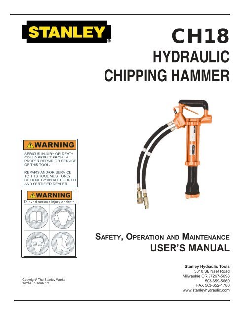
TABLE OF CONTENTSSAFETY SYMBOLS ..................................................................................................................... 4SAFETY PRECAUTIONS ............................................................................................................ 5TOOL STICKERS & TAGS ...........................................................................................................7HYDRAULIC HOSE REQUIREMENTS ....................................................................................... 8HTMA REQUIREMENTS ........................................................................................................... 10OPERATION .............................................................................................................................. 11PREOPERATION PROCEDURES ............................................................................................ 11PREPARATION FOR INITIAL USE ........................................................................................... 11CHECK HYDRAULIC POWER SOURCE ................................................................................. 11CHECK TOOL ........................................................................................................................... 11CHECK TRIGGER MECHANISM ............................................................................................. 11INSTALL TOOL BIT ................................................................................................................... 11CONNECT HOSES ................................................................................................................... 11COLD WEATHER OPERATION ................................................................................................ 11STORAGE ................................................................................................................................. 11TROUBLESHOOTING ............................................................................................................... 12EQUIPMENT PROTECTION & CARE ....................................................................................... 13SPECIFICATIONS ...................................................................................................................... 14<strong>CH18</strong> PARTS ILLUSTRATION ................................................................................................... 15<strong>CH18</strong> PARTS LIST ..................................................................................................................... 16WARRANTY ............................................................................................................................... 17SERVICING THE STANLEY HYDRAULIC <strong>CH18</strong> Chipping Hammer. This manual contains safety, operation,<strong>and</strong> routine maintenance instructions. Stanley Hydraulic Tools recommends that servicing of hydraulictools, other than routine maintenance, must be performed by an authorized <strong>and</strong> certified dealer. Pleaseread the following warning.SERIOUS INJURY OR DEATH COULD RESULT FROM THE IM-PROPER REPAIR OR SERVICE OF THIS TOOL.REPAIRS AND / OR SERVICE TO THIS TOOL MUST ONLY BEDONE BY AN AUTHORIZED AND CERTIFIED DEALER.For the nearest authorized <strong>and</strong> certified dealer, call Stanley Hydraulic Tools at the number listed on theback of this manual <strong>and</strong> ask for a Customer Service Representative.3
SAFETY SYMBOLSSafety symbols <strong>and</strong> signal words, as shown below, are used to emphasize all operator, maintenance <strong>and</strong> repairactions which, if not strictly followed, could result in a life-threatening situation, bodily injury or damage to equipment.This is the safety alert symbol. It is used to alert you to potential personalinjury hazards. Obey all safety messages that follow this symbol to avoidpossible injury or death.This safety alert <strong>and</strong> signal word indicate an imminently hazardous situationwhich, if not avoided, will result in death or serious injury.This safety alert <strong>and</strong> signal word indicate a potentially hazardous situationwhich, if not avoided, could result in death or serious injury.CAUTIONThis safety alert <strong>and</strong> signal word indicate a potentially hazardous situationwhich, if not avoided, may result in minor or moderate injury.CAUTIONNOTICEThis signal word indicates a potentially hazardous situation which, if notavoided, may result in property damage.This signal word indicates a situation which, if not avoided, will result indamage to the equipment.IMPORTANTThis signal word indicates a situation which, if not avoided, may result indamage to the equipment.Always observe safety symbols. They are included for your safety <strong>and</strong> for the protection of the tool.LOCAL SAFETY REGULATIONSEnter any local safety regulations here. Keep these instructions in an area accessible to the operator <strong>and</strong> maintenancepersonnel.4
TOOL STICKERS & TAGSStanley Hydraulic Tools3810 SE Naef RoadMilwaukie, OR 97267MODEL NO.<strong>CH18</strong> SM207-9 4-6 GPM // 26-34 15-23 LPM2000 PSI/ / 140 B BAR28852 NAME TAG03786 GPM STICKERDANGERDANGERThe safety tag (p/n15875) at right is attachedto the tool when shippedfrom the factory. Read<strong>and</strong> underst<strong>and</strong> the safetyinstructions listed on thistag before removal. Wesuggest you retain this tag<strong>and</strong> attach it to the toolwhen not in use.1. FAILURE TO USE HYDRAULIC HOSE LABELEDAND CERTIFIED AS NON-CONDUCTIVE WHENUSING HYDRAULIC TOOLS ON OR NEARELECTRICAL LINES MAY RESULT IN DEATHOR SERIOUS INJURY.BEFORE USING HOSE LABELED AND CERTI-FIED AS NON-CONDUCTIVE ON OR NEARELECTRIC LINES BE SURE THE HOSE ISMAINTAINED AS NON-CONDUCTIVE. THEHOSE SHOULD BE REGULARLY TESTED FORELECTRIC CURRENT LEAKAGE IN ACCOR-DANCE WITH YOUR SAFETY DEPARTMENTINSTRUCTIONS.2. A HYDRAULIC LEAK OR BURST MAY CAUSEOIL INJECTIONI N T O T H EBODY OR CAUSE OTHER SEVERE PERSONALINJURY.A DO NOT EXCEED SPECIFIED FLOW ANDPRESSURE FORTHIS TOOL. EXCESS FLOW OR PRESSUREIMPORTANTREAD OPERATION MANUAL ANDSAFETY INSTRUCTIONS FOR THISTOOL BEFORE USING IT.USE ONLY PARTS AND REPAIRPROCEDURES APPROVED BYSTANLEY AND DESCRIBED IN THEOPERATION MANUAL.TAG TO BE REMOVED ONLY BYTOOL OPERATOR.SAFETY TAG P/N 15875D DO NOT LIFT OR CARRY TOOL BY THEHOSES. DO NOT ABUSE HOSE. DO NOTUSE KINKED, TORN OR DAMAGED HOSE.3. MAKE SURE HYDRAULIC HOSES ARE PROP-ERLY CONNECTED TO THE TOOL BEFOREPRESSURING SYSTEM. SYSTEM PRESSUREHOSE MUST ALWAYS BE CONNECTED TO TOOL“IN” PORT. SYSTEM RETURN HOSE MUSTALWAYS BE CONNECTED TO TOOL “OUT” PORT.REVERSING CONNECTIONS MAY CAUSE RE-VERSE TOOL OPERATION WHICH CAN RESULTIN SEVERE PERSONAL INJURY.4. DO NOT CONNECT OPEN-CENTER TOOLS TOCLOSED-CENTER HYDRAULIC SYSTEMS. THISMAY RESULT IN LOSS OF OTHER HYDRAULICFUNCTIONS POWERED BY THE SAME SYSTEMAND/OR SEVERE PERSONAL INJURY.5. BYSTANDERS MAY BE INJURED IN YOUR WORKAREA. KEEP BYSTANDERS CLEAR OF YOURWORK AREA.IMPORTANTREAD OPERATION MANUAL ANDSAFETY INSTRUCTIONS FOR THISTOOL BEFORE USING IT.USE ONLY PARTS AND REPAIRPROCEDURES APPROVED BYSTANLEY AND DESCRIBED IN THEOPERATION MANUAL.TAG TO BE REMOVED ONLY BYTOOL OPERATOR.(shown smaller then actual size)7
HYDRAULIC HOSE REQUIREMENTSHOSE TYPESThe rated working pressure of the hydraulic hose must be equal to or higher than the relief valve setting on thehydraulic system. There are three types of hydraulic hose that meet this requirement <strong>and</strong> are authorized for usewith Stanley Hydraulic Tools. They are:Certified non-conductive - constructed of thermoplastic or synthetic rubber inner tube, synthetic fi berbraid reinforcement, <strong>and</strong> weather resistant thermoplastic or synthetic rubber cover. Hose labeled certified nonconductiveis the only hose authorized for use near electrical conductors.Wire-braided (conductive) - constructed of synthetic rubber inner tube, single or double wire braid reinforcement,<strong>and</strong> weather resistant synthetic rubber cover. This hose is conductive <strong>and</strong> must never be used nearelectrical conductors.Fabric-braided (not certifi ed or labeled non-conductive) - constructed of thermoplastic or synthetic rubberinner tube, synthetic fi ber braid reinforcement, <strong>and</strong> weather resistant thermoplastic or synthetic rubber cover. Thishose is not certified non-conductive <strong>and</strong> must never be used near electrical conductors.HOSE SAFETY TAGSTo help ensure your safety, the following DANGER tags are attached to all hose purchased from Stanley HydraulicTools. DO NOT REMOVE THESE TAGS.If the information on a tag is illegible because of wear or damage, replace the tag immediately. A new tag may beobtained from your Stanley Distributor.THE TAG SHOWN BELOW IS ATTACHED TO “CERTIFIED NON-CONDUCTIVE” HOSEDO NOT REMOVE THIS TAGD A N G E R1 FAILURE TO USE HYDRAULIC HOSE LABELED AND CERTIFIED AS NON-CONDUCTIVEWHEN USING HYDRAULIC TOOLS ON OR NEAR ELECTRIC LINES MAY RESULT IN DEATHOR SERIOUS INJURY.FOR PROPER AND SAFE OPERATION MAKE SURE THAT YOU HAVE BEEN PROPERLYTRAINED IN CORRECT PROCEDURES REQUIRED FOR WORK ON OR AROUNDELECTRIC LINES.2. BEFORE USING HYDRAULIC HOSE LABELED AND CERTIFIED AS NON-CONDUCTIVE ONOR NEAR ELECTRIC LINES. WIPE THE ENTIRE LENGTH OF THE HOSE AND FITTINGWITH A CLEAN DRY ABSORBENT CLOTH TO REMOVE DIRT AND MOISTURE AND TESTHOSE FOR MAXIMUM ALLOWABLE CURRENT LEAKAGE IN ACCORDANCE WITH SAFETYDEPARTMENT INSTRUCTIONS.D A N G E R3. DO NOT EXCEED HOSE WORKING PRESSURE OR ABUSE HOSE. IMPROPER USE ORHANDLING OF HOSE COULD RESULT IN BURST OR OTHER HOSE FAILURE. KEEPHOSE AS FAR AWAY AS POSSIBLE FROM BODY AND DO NOT PERMIT DIRECT CONTACTDURING USE. CONTACT AT THE BURST CAN CAUSE BODILY INJECTION AND SEVEREPERSONAL INJURY.4. HANDLE AND ROUTE HOSE CAREFULLY TO AVOID KINKING, ABRASION, CUTTING, ORCONTACT WITH HIGH TEMPERATURE SURFACES. DO NOT USE IF KINKED. DO NOT USEHOSE TO PULL OR LIFT TOOLS, POWER UNITS, ETC.5. CHECK ENTIRE HOSE FOR CUTS CRACKS LEAKS ABRASIONS, BULGES, OR DAMAGE TOCOUPLINGS IF ANY OF THESE CONDITIONS EXIST, REPLACE THE HOSE IMMEDIATELY.NEVER USE TAPE OR ANY DEVICE TO ATTEMPT TO MEND THE HOSE.6. AFTER EACH USE STORE IN A CLEAN DRY AREA.DO NOT REMOVE THIS TAGSIDE 1 SIDE 23 (shown smaller than actual size)THE TAG SHOWN BELOW IS ATTACHED TO “CONDUCTIVE” HOSE.DO NOT REMOVE THIS TAGD A N G E R1 DO NOT USE THIS HYDRAULIC HOSE ON OR NEAR ELECTRIC LINES. THIS HOSE ISNOT LABELED OR CERTIFIED AS NON-CONDUCTIVE. USING THIS HOSE ON OR NEARELECTRICAL LINES MAY RESULT IN DEATH OR SERIOUS INJURY.2. FOR PROPER AND SAFE OPERATION MAKE SURE THAT YOU HAVE BEEN PROPERLYTRAINED IN CORRECT PROCEDURES REQUIRED FOR WORK ON OR AROUNDELECTRIC LINES.3. DO NOT EXCEED HOSE WORKING PRESSURE OR ABUSE HOSE. IMPROPER USE ORHANDLING OF HOSE COULD RESULT IN BURST OR OTHER HOSE FAILURE. KEEPHOSE AS FAR AWAY AS POSSIBLE FROM BODY AND DO NOT PERMIT DIRECT CONTACTDURING USE. CONTACT AT THE BURST CAN CAUSE BODILY INJECTION AND SEVEREPERSONAL INJURY.4. HANDLE AND ROUTE HOSE CAREFULLY TO AVOID KINKING, CUTTING, OR CONTACTWITH HIGH TEMPERATURE SURFACES. DO NOT USE IF KINKED. DO NOT USE HOSE TOPULL OR LIFT TOOLS, POWER UNITS, ETC.D A N G E R5. CHECK ENTIRE HOSE FOR CUTS CRACKS LEAKS ABRASIONS, BULGES, OR DAMAGE TOCOUPLINGS IF ANY OF THESE CONDITIONS EXIST, REPLACE THE HOSE IMMEDIATELY.NEVER USE TAPE OR ANY DEVICE TO ATTEMPT TO MEND THE HOSE.6. AFTER EACH USE STORE IN A CLEAN DRY AREA.DO NOT REMOVE THIS TAGSEE OTHER SIDESIDE 1 SIDE 2(shown smaller than actual size)8
Tool to Hydraulic Circuit Hose RecommendationsThe chart to the right shows recommended minimumhose diameters for various hose lengthsbased on gallons per minute (gpm)/liters per minute(lpm). These recommendations are intendedto keep return line pressure (back pressure) to aminimum acceptable level to ensure maximum toolperformance.This chart is intended to be used for hydraulic toolapplications only based on Stanley Hydraulic Toolstool operating requirements <strong>and</strong> should not be usedfor any other applications.All hydraulic hose must have at least a ratedminimum working pressure equal to the maximumhydraulic system relief valve setting.All hydraulic hose must meet or exceed specificationsas set forth by SAE J517.Oil Flow Hose Lengths Inside Diameter USE Min. Working PressureGPM LPM FEET METERS INCH MM (Press/Return) PSI BARCertified Non-Conductive Hose - Fiber Braid - for Utility Bucket Trucks4-9 15-34 up to 10 up to 3 3/8 10 Both 2250 155Conductive Hose - Wire Braid or Fiber Braid -DO NOT USE NEAR ELECTRICAL CONDUCTORS4-6 15-23 up to 25 up to 7.5 3/8 10 Both 2500 1754-6 15-23 26-100 7.5-30 1/2 13 Both 2500 1755-10.5 19-40 up to 50 up to 15 1/2 13 Both 2500 1755-10.5 19-40 51-100 15-30 5/8 16 Both 2500 1755/8 16 Pressure 2500 1755-10.5 19-40 100-300 30-903/4 19 Return 2500 17510-13 38-49 up to 50 up to 15 5/8 16 Both 2500 17510-13 38-49 51-100 15-3010-13 38-49 100-200 30-6013-16 49-60 up to 25 up to 85/8 16 Pressure 2500 1753/4 19 Return 2500 1753/4 19 Pressure 2500 1751 25.4 Return 2500 1755/8 16 Pressure 2500 1753/4 19 Return 2500 17513-16 49-60 26-100 8-303/4 19 Pressure 2500 1751 25.4 Return 2500 175PRESSURE>Typical Hose Connections9
HTMA REQUIREMENTSTOOL CATEGORYHYDRAULIC SYSTEMREQUIREMENTS TYPE 1 TYPE II TYPE III TYPE RRFLOW RATETOOL OPERATING PRESSURE(at the power supply outlet)SYSTEM RELIEF VALVE SETTING(at the power supply outlet)MAXIMUM BACK PRESSURE(at tool end of the return hose)Measured at a max. fl uid viscosity of:(at min. operating temperature)TEMPERATURESuffi cient heat rejection capacityto limit max. fl uid temperature to:(at max. expected ambient temperature)4-6 gpm 7-9 gpm 11-13 gpm 9-10.5 gpm(15-23 lpm) (26-34 lpm) (42-49 lpm) (34-40 lpm)2000 psi 2000 psi 2000 psi 2000 psi(138 bar) (138 bar) (138 bar) (138 bar)2100-2250 psi 2100-2250 psi 2100-2250 psi 2200-2300 psi(145-155 bar) (145-155 bar) (145-155 bar) (152-159 bar)250 psi 250 psi 250 psi 250 psi(17 bar) (17 bar) (17 bar) (17 bar)400 ssu* 400 ssu* 400 ssu* 400 ssu*(82 centistokes) (82 centistokes) (82 centistokes) (82 centistokes)140° F 140° F 140° F 140° F(60° C) (60° C) (60° C) (60° C)Min. cooling capacityat a temperature difference ofbetween ambient <strong>and</strong> fl uid tempsNOTE:Do not operate the tool at oil temperatures above 140° F (60° C). Operation at higher temperatures can cause operatordiscomfort at the tool.FILTERMin. full-fl ow fi ltrationSized for fl ow of at least:(For cold temp. startup <strong>and</strong> max. dirt-holding capacity)3 hp 5 hp 7 hp 6 hp(2.24 kW) (3.73 kW) (4.47 kW) (5.22 kW)40° F 40° F 40° F 40° F(22° C) (22° C) (22° C) (22° C)25 microns 25 microns 25 microns 25 microns30 gpm 30 gpm 30 gpm 30 gpm(114 lpm) (114 lpm) (114 lpm) (114 lpm)HYDRAULIC FLUIDPetroleum based(premium grade, anti-wear, non-conductive)VISCOSITY(at min. <strong>and</strong> max. operating temps)100-400 ssu* 100-400 ssu* 100-400 ssu* 100-400 ssu*(20-82 centistokes)NOTE:When choosing hydraulic fl uid, the expected oil temperature extremes that will be experienced in service determine themost suitable temperature viscosity characteristics. Hydraulic fl uids with a viscosity index over 140 will meet the requirementsover a wide range of operating temperatures.*SSU = Saybolt Seconds UniversalNOTE:These are general hydraulic system requirements. See tool Specifi cation page for tool specifi c requirements.10
OPERATIONPREOPERATION PROCEDURESPREPARATION FOR INITIAL USEThe tool, as shipped, has no special unpacking or assemblyrequirements prior to usage. Inspection to assure the toolwas not damaged in shipping <strong>and</strong> does not contain packingdebris is all that is required.CHECK HYDRAULIC POWER SOURCE1. Using a calibrated fl owmeter <strong>and</strong> pressure gauge, checkthat the hydraulic power source develops a fl ow of 7-9 gpm/26-34 lpm at 1500-2000 psi/105-140 bar.2. Make certain the hydraulic power source is equippedwith a relief valve set to open at 2100-2250 psi/145-155 barminimum.3. Check that the hydraulic circuit matches the tool for opencenter(OC) operation.CHECK TOOL1. Make sure all tool accessories are correctly installed. Failureto install tool accessories properly can result in damageto the tool or personal injury.2. There should be no signs of leaks.3. The tool should be clean, with all fi ttings <strong>and</strong> fastenerstight.2. Connect the hoses from the hydraulic power source to thehose couplers on the tool. It is a good practice to connect thereturn hose fi rst <strong>and</strong> disconnect it last to minimize or avoidtrapped pressure within the tool.3. Observe fl ow indicators stamped on hose couplers to besure that oil will flow in the proper direction. The female coupleris the inlet coupler.NOTE:The pressure increase in uncoupled hoses left in the sunmay result in making them difficult to connect. Whenpossible, connect the free ends of operating hoses together.OPERATING PROCEDURES1. Observe all safety precautions.2. Move the hydraulic circuit control valve to the “ON”position.3. Place the tool bit fi rmly on the surface you are to workon.4. squeeze the trigger to start the tool. Adequate downpressure is very important.NOTICENot for Underwater use.CHECK TRIGGER MECHANISM1. Check that the trigger operates smoothly <strong>and</strong> is free totravel between the “ON” <strong>and</strong> “OFF” positions.INSTALL TOOL BITThe tool accepts st<strong>and</strong>ard 7/8 x 3-1/4 inch hex shank toolbits.TO INSTALL A HEX SHANK TOOL BITCOLD WEATHER OPERATIONIf the tool is to be used during cold weather, preheat the hydraulicfl uid at low engine speed. When using the normallyrecommended fl uids, fl uid temperature should be at or above50° F/10° C (400 ssu/82 centistokes) before use.STORAGE1. Push in the retainer, insert the hex shank tool bit <strong>and</strong> movethe retainer back into locked position. Note the orientation ofthe particular tool bit that is being installed.CONNECT HOSES1. Wipe all hose couplers with a clean lint-free cloth beforemaking connections.111. Disconnect the tool from the hydraulic power source.2. Remove the tool bit <strong>and</strong> spray the tool bit retainer area withWD-40 inside <strong>and</strong> out.3. Wipe clean <strong>and</strong> store in a clean, dry place.
TROUBLESHOOTINGIf symptoms of poor performance develop, the following chart can be used as a guide to correct the problem.When diagnosing faults in operation of the grinder, always check that the hydraulic power source is supplying the correcthydraulic fl ow <strong>and</strong> pressure to the grinder as listed in the table. Use a fl owmeter known to be accurate. Check the fl owwith the hydraulic oil temperature at least 80°F/27°C.Tool does not run.PROBLEM CAUSE SOLUTIONTool does not hit effectively.Tool operates slow.Power unit not functioning.Couplers or hoses blocked.Pressure <strong>and</strong> return line hoses reversedat ports.Mechanical failure of piston or internalparts.Power unit not functioning.Couplers or hoses blocked.Fluid too hot (above 140“ F/ 60“ C).Incorrect tool bit.Low oil fl ow from power unit.High back-pressure.Check power unit for proper fl ow <strong>and</strong>pressure 7-9 gpm/26-34 lpm, 1500-2000psi/105-140 bar.Remove restriction.Be sure hoses are connected to theirproper ports.Have inspected <strong>and</strong> repaired by anauthorized dealer.Check power unit for proper fl ow <strong>and</strong>pressure 7-9 gpm/26-34 lpm, 1500-2000psi/105-140 bar.Remove restriction.Provide cooler to maintain proper fl uidtemperature.Ensure tool bit meets specifi cations.Check power source for proper fl ow.Check hydraulic system for excessiveback-pressure <strong>and</strong> correct as required.12
EQUIPMENT PROTECTION & CARENOTICEIn addition to the SafetyPrecautions in this manual,observe the following forequipment protection <strong>and</strong>care.• Make sure all couplers are wiped clean before connection.• The hydraulic circuit control valve must be in the “OFF” position when coupling or uncouplinghydraulic tools. Failure to do so may result in damage to the quick couplers <strong>and</strong> cause overheatingof the hydraulic system.• Always store the tool in a clean dry space, safe from damage or pilferage.• Make sure the circuit PRESSURE hose (with male quick disconnect) is connected to the “IN” port.The circuit RETURN hose (with female quick disconnect) is connected to the opposite port. Do notreverse circuit fl ow. This can cause damage to internal seals.• Always replace hoses, couplings <strong>and</strong> other parts with replacement parts recommended by StanleyHydraulic Tools. Supply hoses must have a minimum working pressure rating of 2500 psi/172 bar.• Do not exceed the rated fl ow (see Specifi cations) in this manual for correct fl ow rate <strong>and</strong>model number. Rapid failure of the internal seals may result.• Always keep critical tool markings, such as warning stickers <strong>and</strong> tags legible.• Tool repair should be performed by experienced personnel only.• Make certain that the recommended relief valves are installed in the pressure side of the system.• Do not use the tool for applications for which it was not intended.13
SPECIFICATIONSWeight ........................................................................................................................................................... 24 lbs / 10.9 kgPressure Range.........................................................................................................................1500-2000 psi / 105-140 barFlow Range ............................................................................................................................................7-9 gpm / 26-34 lpmOptimum Flow ................................................................................................................................................8 gpm / 30 lpmPorting ........................................................................................................................................ 3/8 in. Male Pipe Hose EndLength............................................................................................................................................................... 20 in. / 51 cmSystem Type ...................................................................................................................................................... Open CenterAccessory Shank ..................................................................................................................................7/8 in. Hex x 3-1/4 in.14
<strong>CH18</strong> PARTS ILLUSTRATION15
<strong>CH18</strong> PARTS LISTITEMNO.PARTNO.QTYDESCRIPTION1 02890 1 HANDLE BODY ASSY2 02853 1 TRIGGER3 24316 1 DOWEL PIN4 02959 1 SPOOL SCREW5 24348 1 WASHER6 02901 1 O-RING7 03252 2 O-RING8 01412 2 HOSE ASSY9 02846 1 SPRING10 02881 1 ON/OFF SPOOL - OPEN CENTER11 03252 2 O-RING12 00752 1 RETAINING RING13 03973 1 MALE COUPLER BODYSEAL KIT PART NUMBER 03331PART NO. QTY DESCRIPTION02901 1 O-RING03252 2 O-RING02865 2 BACK-UP RING02177 2 O-RING03127 1 ROD WIPER02302 1 ROD SEAL01259 1 O-RING01772 1 O-RING00211 2 O-RING02907 2 ROD SEAL14 03972 1 FEMALE COUPLER BODY15 28852 1 NAME TAG16 03786 1 GPM STICKER17 02870 1 OUTER TUBE18 03958 1 OIL TUBE19 01259 1 O-RING20 03253 1 VALVE BODY21 02848 4 BOLT ASSY (INCL ITEM 26)22 02880 1 REVERSING SPOOL23 00211 2 O-RING24 03254 1 VALVE GLAND25 01772 1 O-RING26 02454 4 ALLEN NUT (FURNISHED WITH ITEM 21)27 02177 2 O-RING28 02865 2 BACK-UP RING29 03959 1 PISTON30 02907 2 ROD SEAL31 04175 1 INSERT32 ---- -- NO ITEM33 04005 1 RETAINER NOSE04006 1 RETAINER NOSE UNDERWATER34 04012 1 RETAINER35 03190 2 SPRING36 02436 2 BALL37 04010 1 RETAINER CAP38 02665 2 CAPSCREW39 02843 1 PIN40 07049 1 INSERT41 03031 2 LOCKWASHER42 69400 1 FLOW SLEEVE16
WARRANTYStanley Hydraulic Tools (hereinafter called “Stanley”), subject to the exceptions contained below, warrants new hydraulic tools for a period of one year from the date of sale tothe fi rst retail purchaser, or for a period of 2 years from the shipping date from Stanley, whichever period expires fi rst, to be free of defects in material <strong>and</strong>/or workmanship atthe time of delivery, <strong>and</strong> will, at its option, repair or replace any tool or part of a tool, or new part, which is found upon examination by a Stanley authorized service outlet or byStanley’s factory in Milwaukie, Oregon to be DEFECTIVE IN MATERIAL AND/OR WORKMANSHIP.EXCEPTIONS FROM WARRANTYNEW PARTS: New parts which are obtained individually are warranted, subject to the exceptions herein, to be free of defects in material <strong>and</strong>/or workmanship at the timeof delivery <strong>and</strong> for a period of 6 months after the date of fi rst usage. Seals <strong>and</strong> diaphragms are warranted to be free of defects in material <strong>and</strong>/or workmanship at the timeof delivery <strong>and</strong> for a period of 6 months after the date of fi rst usage or 2 years after the date of delivery, whichever period expires fi rst. Warranty for new parts is limited toreplacement of defective parts only. Labor is not covered.FREIGHT COSTS: Freight costs to return parts to Stanley, if requested by Stanley for the purpose of evaluating a warranty claim for warranty credit, are covered under thispolicy if the claimed part or parts are approved for warranty credit. Freight costs for any part or parts which are not approved for warranty credit will be the responsibility of theindividual.SEALS & DIAPHRAGMS: Seals <strong>and</strong> diaphragms installed in new tools are warranted to be free of defects in material <strong>and</strong>/or workmanship for a period of 6 months after thedate of fi rst usage, or for a period of 2 years from the shipping date from Stanley, whichever period expires fi rst.CUTTING ACCESSORIES: Cutting accessories such as breaker tool bits are warranted to be free of defects in material <strong>and</strong> or workmanship at the time of delivery only.ITEMS PRODUCED BY OTHER MANUFACTURERS: Components which are not manufactured by Stanley <strong>and</strong> are warranted by their respective manufacturers.a. Costs incurred to remove a Stanley manufactured component in order to service an item manufactured by other manufacturers.ALTERATIONS & MODIFICATIONS: Alterations or modifi cations to any tool or part. All obligations under this warranty shall be terminated if the new tool or part is altered ormodifi ed in any way.NORMAL WEAR: any failure or performance defi ciency attributable to normal wear <strong>and</strong> tear such as tool bushings, retaining pins, wear plates, bumpers, retaining rings <strong>and</strong>plugs, rubber bushings, recoil springs, etc.INCIDENTAL/CONSEQUENTIAL DAMAGES: To the fullest extent permitted by applicable law, in no event will STANLEY be liable for any incidental, consequential or specialdamages <strong>and</strong>/or expenses.FREIGHT DAMAGE: Damage caused by improper storage or freight h<strong>and</strong>ling.LOSS TIME: Loss of operating time to the user while the tool(s) is out of service.IMPROPER OPERATION: Any failure or performance defi ciency attributable to a failure to follow the guidelines <strong>and</strong>/or procedures as outlined in the tool’s operation <strong>and</strong>maintenance manual.MAINTENANCE: Any failure or performance defi ciency attributable to not maintaining the tool(s) in good operating condition as outlined in the Operation <strong>and</strong> Maintenance<strong>Manual</strong>.HYDRAULIC PRESSURE & FLOW, HEAT, TYPE OF FLUID: Any failure or performance defi ciency attributable to excess hydraulic pressure, excess hydraulic back-pressure,excess hydraulic fl ow, excessive heat, or incorrect hydraulic fl uid.REPAIRS OR ALTERATIONS: Any failure or performance defi ciency attributable to repairs by anyone which in Stanley’s sole judgement caused or contributed to the failureor defi ciency.MIS-APPLICATION: Any failure or performance defi ciency attributable to mis-application. “Mis-application” is defi ned as usage of products for which they were not originallyintended or usage of products in such a matter which exposes them to abuse or accident, without fi rst obtaining the written consent of Stanley. PERMISSION TO APPLY ANYPRODUCT FOR WHICH IT WAS NOT ORIGINALLY INTENDED CAN ONLY BE OBTAINED FROM STANLEY ENGINEERING.WARRANTY REGISTRATION: STANLEY ASSUMES NO LIABILITY FOR WARRANTY CLAIMS SUBMITTED FOR WHICH NO TOOL REGISTRATION IS ON RECORD. Inthe event a warranty claim is submitted <strong>and</strong> no tool registration is on record, no warranty credit will be issued without fi rst receiving documentation which proves the sale ofthe tool or the tools’ fi rst date of usage. The term “DOCUMENTATION” as used in this paragraph is defi ned as a bill of sale, or letter of intent from the fi rst retail customer. AWARRANTY REGISTRATION FORM THAT IS NOT ALSO ON RECORD WITH STANLEY WILL NOT BE ACCEPTED AS “DOCUMENTATION”.NO ADDITIONAL WARRANTIES OR REPRESENTATIONSThis limited warranty <strong>and</strong> the obligation of Stanley thereunder is in lieu of all other warranties, expressed or implied including merchantability or fi tness for a particular purposeexcept for that provided herein. There is no other warranty. This warranty gives the purchaser specifi c legal rights <strong>and</strong> other rights may be available which mightvary depending upon applicable law.17
18Stanely Hydraulic Tools3810 SE Naef RoadMilwaukie, Oregon503-659-5660 / Fax 503-652-1780www.stanleyhydraulic.com


