Principle of a dual-band search coil magnetometer: a new ... - LPP
Principle of a dual-band search coil magnetometer: a new ... - LPP
Principle of a dual-band search coil magnetometer: a new ... - LPP

Create successful ePaper yourself
Turn your PDF publications into a flip-book with our unique Google optimized e-Paper software.
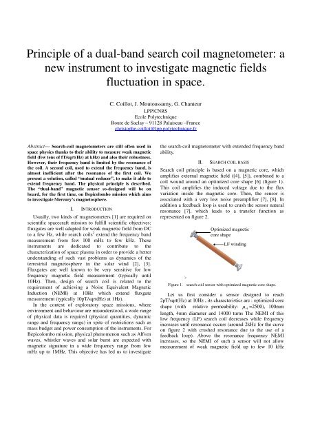
<strong>Principle</strong> <strong>of</strong> a <strong>dual</strong>-<strong>band</strong> <strong>search</strong> <strong>coil</strong> <strong>magnetometer</strong>: a<strong>new</strong> instrument to investigate magnetic fieldsfluctuation in space.C. Coillot, J. Moutoussamy, G. Chanteur<strong>LPP</strong>/CNRSEcole PolytechniqueRoute de Saclay – 91128 Palaiseau –Francechristophe.<strong>coil</strong>lot@lpp.polytechnique.frAbstract— Search-<strong>coil</strong> <strong>magnetometer</strong>s are still <strong>of</strong>ten used inspace physics thanks to their ability to measure weak magneticfield (few tens <strong>of</strong> fT/sqrt(Hz) at kHz) and also their robustness.However, their frequency <strong>band</strong> is limited by the resonance <strong>of</strong>the <strong>coil</strong>. A second <strong>coil</strong>, used to extend the frequency <strong>band</strong>, isalmost inefficient after the resonance <strong>of</strong> the first <strong>coil</strong>. Wepresent a solution, called “mutual reducer”, to make it able toextend frequency <strong>band</strong>. The physical principle is described.The “<strong>dual</strong>-<strong>band</strong>” magnetic sensor so-designed will be onboard, for the first time, on Bepicolombo mission which aimsto investigate Mercury’s magnetosphere.I. INTRODUCTIONUsually, two kinds <strong>of</strong> <strong>magnetometer</strong>s [1] are required onscientific spacecraft mission to fulfill scientific objectives:fluxgates are well adapted for weak magnetic field from DCto a few Hz, while <strong>search</strong> <strong>coil</strong>s 2 extend the frequency <strong>band</strong>measurement from few 100 mHz to few kHz. Theseinstruments are dedicated to contribute to thecharacterization <strong>of</strong> space plasma in order to provide a betterunderstanding <strong>of</strong> such vast problems as dynamics <strong>of</strong> theterrestrial magnetosphere in the solar wind [2], [3].Fluxgates are well known to be very sensitive for lowfrequency magnetic field measurement (typically until10Hz). Then, design <strong>of</strong> <strong>search</strong> <strong>coil</strong> is related to therequirement <strong>of</strong> achieving a Noise Equivalent MagneticInduction (NEMI) at 10Hz which extend fluxgatemeasurement (typically 10pT/sqrt(Hz) at 1Hz).In the context <strong>of</strong> exploratory space missions, whereenvironment and behaviour are misunderstood, a wide range<strong>of</strong> physical data is required (physical quantities, dynamicrange and frequency range) in spite <strong>of</strong> restrictions such asmass budget and power consumption <strong>of</strong> the instruments. ForBepicolombo mission, physical phenomenon such as Alfvenwaves, whistler waves and solar burst are expected withmagnetic signature in a wide frequency range from fewmHz up to 1MHz. This objective has led us to investigatethe <strong>search</strong>-<strong>coil</strong> <strong>magnetometer</strong> with extended frequency <strong>band</strong>ability.II.SEARCH COIL BASISSearch <strong>coil</strong> principle is based on a magnetic core, whichamplifies external magnetic field ([4], [5]), combined to a<strong>coil</strong> wound around an optimized core shape [6] (figure 1).This <strong>coil</strong> amplifies the induced voltage due to the fluxvariation inside the magnetic core. Then, the sensor isassociated with a very low noise preamplifier [7], [8]. Inaddition a feedback loop is used to crush the sensor naturalresonance [7], which leads to a transfer function asrepresented on figure 2.Optimized magneticcore shapeLF windingFigure 1. <strong>search</strong> <strong>coil</strong> sensor with optimized magnetic core shape.Let us first consider a sensor designed to reach2pT/sqrt(Hz) at 10Hz , its characteristics are : optimized coreshape (with relative permeability: µ ri =2500), 100mmlength, 4mm diameter and 14000 turns The NEMI <strong>of</strong> thislow frequency (LF) <strong>search</strong> <strong>coil</strong> decreases while frequencyincreases until resonance occurs (around 2kHz for the curveon figure 2 with crushed resonance due to the use <strong>of</strong> afeedback loop). Above the resonance frequency NEMIincreases, so the NEMI <strong>of</strong> such a sensor will not allowmeasurement <strong>of</strong> weak magnetic field up to few 10 kHz
which is necessary to investigate unknown magnetospheresuch as Mercury one.BextN1*S*µappd/dtL11 27.5HR11kC155p0Figure 3. Equivalent electrical circuit <strong>of</strong> <strong>search</strong> <strong>coil</strong>.Transmittance <strong>of</strong> <strong>search</strong> <strong>coil</strong> permits to express moreaccurately NEMI frequency behavior:Figure 2. Transfer function and NEMI curve <strong>of</strong> a LF <strong>search</strong> <strong>coil</strong>.III.FREQUENCY BEHAVIOR DISCUSSIONInduced voltage which appears on the winding is:dϕ(t)e( t)= −N1⇒ E = N1S< µ app > ωB, (1)dtjwtEewhere e = , N 1 is the turn number, S is the coresection, ω = 2πfis the pulsation, µ > is the average< appapparent permeability and B is the flux density. Nextinduced voltage is compared to noise sources (thermal noise4kTR 1 and voltage noise from amplifier e PA ):2 21Sµ app > B)= ePA+ 4( N < ω kTR (2)NEMI is then defined as the smallest magnetic field (B)which can be detected beyond the noise:2PAe + 4kTRNEMI = (3)N Sµ11appωFrom (3) it can be deduced that NEMI <strong>of</strong> <strong>search</strong> <strong>coil</strong> isimproved (i.e. NEMI is smaller) when frequency increases.In order to reach a NEMI value at a given frequency (in ourcase 2pT/sqrt(Hz) at 10Hz), one can use (3) to computerequired turn number (N). Then, we assume that sensorbehaves like RLC circuit (Figure 3. ). More modeling detailsare given in [6], [7] and[8]. From equivalent circuit <strong>of</strong> figure3 one can deduce transfer function between output voltageand external magnetic field:V − jωN1SµappT ( jω)= =(4)B2(1 − L C ω ) + jR C ω111112PAe + 4kTR12 22NEMI = (1 − L1C1ω) + ( R1C1ω) (5)N Sµ ω1appEquation (5) <strong>of</strong> NEMI shows clearly that aboveresonance frequency (i.e. ω < 1/ LC ) the induced voltageis reduced from the capacitive behavior <strong>of</strong> the sensor whileNEMI value increases (i.e. becomes worst).IV. FEASIBILITY OF SEARCH COIL USING TWO WINDINGSON A SAME MAGNETIC CORE TO EXTEND FREQUENCY RANGEObviously, first idea is to use a second winding with ahigher resonance frequency to extend the frequency rangemeasurement. Let us examine an “intuitive” design <strong>of</strong> such awinding (referred as “HF” winding). The design <strong>of</strong> suchwinding is obtained by translating the NEMI curve on thefigure 2 to the starting point <strong>of</strong> the desired extendedfrequency <strong>band</strong>. We consider a LF <strong>band</strong> which stops at 10kHz. From figure 2 we deduct a NEMI equal to100fT/sqrt(Hz) which gives us the starting point <strong>of</strong> thedesign <strong>of</strong> the HF winding. Then, from (3) we canextrapolate the design <strong>of</strong> the HF <strong>coil</strong>. We consider themagnetic core is the same and equivalent noise is also thesame. So on, we express the turn number <strong>of</strong> the HF <strong>coil</strong> fromthe turn number <strong>of</strong> the LF <strong>coil</strong>, multiplied by the ratio <strong>of</strong> tw<strong>of</strong>requencies (6). These frequencies correspond to thefrequency ω 1 such as NEMI for the LF is 100fT/sqrt(Hz),that is approximately 200Hz (from figure 2) and thefrequency ω 2 such as NEMI for the HF is 100fT/sqrt(Hz),that is 10kHz (as desired).N2ω1N1≈ N1≈ω 50Such winding has been implemented in twoconfigurations. First, the HF winding, N2=280 turns, hasbeen implemented on a magnetic core alone. Second, the HFwinding has been implemented on the complete <strong>search</strong> <strong>coil</strong>sensor (LF winding on magnetic core) and what happens?2(6)
N1BµappSφ 2 = N2BµappS+ L2I2 − M12(11)L1φ = ( N −σNBµ app S + L I (12)2 2 2 )22Coefficient σ represents a mutual coupling coefficientbetween the two windings. When, windings are realized on asame magnetic core, this coefficient σ is almost 1 and weobtain:Figure 4. Transfer functions for HF winding on a magnetic core (HF1)and HF winding on a magnetic core associated to LF winding (HF2).When the HF winding is realized directly on a magneticcore, his behavior is compliant with expected one (4).Transfer function (HF1 curve on Figure 4) increases until theresonance occurs at 300 kHz, then transfer functiondecreases due to the capacitive behavior <strong>of</strong> the winding. Onthe other hand, when a LF winding is wound on the magneticcore (HF2 curve on Figure 4), the HF winding exhibits aninduced voltage which increases until the resonancefrequency <strong>of</strong> the LF winding occurs (at about 6 kHz). Abovethis frequency an anti-resonance occurs and induced voltageincreases but remains 20dB below what is obtained for theHF winding alone on the magnetic core. To understand thisphenomenon, let us express magnetic flux <strong>of</strong> each winding.Index 1 and 2 represent respectively LF and HF winding.φ (7)1 = N1Bµapp S + L1I1+ M 21I2φ (13)2 ≈ L2I2In this latter expression, part <strong>of</strong> the flux which isdependant <strong>of</strong> magnetic field has disappeared and themagnetic field can not be measured with a second windingafter the resonance <strong>of</strong> the first one. In such a way a secondwinding on a same magnetic core is inefficient to extendfrequency <strong>band</strong> measurement.V. PHYSICAL DESCRIPTION OF A MUTUAL REDUCERIn order to extend frequency range measurement with anHF winding it will be needed to reduce mutual couplingfrom one winding on the other one. The original way wepropose to do that, consists in using a magnetic materialwhich surrounds the first winding as described on figure 5.This “mutual reducer” permits to the self-induction flux <strong>of</strong>the LF winding to find a path through the mutual reducer(red lines on figure 6). It results, that self-induction flux fromLF winding seen by HF winding is considerably decreased.φ (8)2 = N 2Bµapp S + L2I2 + M12I1LF windingHF windingThe current flowing the LF winding ( I 1 ), is given by:N1BSµapp jωI1= −. (9)R + jL ω + /( jC ω)111 1For frequency lower than resonance frequency thecurrent value is weak. After resonance frequency, the maincontribution in the impedance value <strong>of</strong> the winding comesfrom the inductive part: jL ω . Equation (9) becomes:I111N1BSµapp≈ −(when ω > 1 L1C1 ) (10)LSimplified expression <strong>of</strong> the current (10) is substitutedinside (8), which becomes:Mutual reducerMagnetic coreFigure 5. <strong>dual</strong>-<strong>band</strong> <strong>search</strong> <strong>coil</strong> <strong>magnetometer</strong> consists in two winding ona magnetic core separated by a cylindrical magnetic core (mutual reducer).Another consequence is that apparent permeability arenow different for the two windings ( µ is replaced eitherby µ app1for LF winding or by µ app2for HF winding).Values <strong>of</strong> the apparent permeability ( µ app1and µ app2)mainly depend on the shape <strong>of</strong> the mutual reducer. Theparameters <strong>of</strong> the sensor: mutual induction coefficient, autoinductionand apparent permeability can be obtained fromapp
numerical computation with electromagnetism s<strong>of</strong>tware.Then, the expression <strong>of</strong> flux under HF winding becomes:N1µapp1BextS1φ 2 = N2µapp2BextS2− L2I2− M12(11)L12 = µ app−eqN2BextS2− L2I2φ (11)M N S1− (11)S12 1µ app eq = µ app2− µ app1L1N22This equation shows that mutual coupling must be loweras possible to makes the apparent permeability ( µ−)app eqhigher as possible. The auto induction flux will notcompensate the flux created by the magnetic field to bemeasured. As shown on figure 6 the magnetic field linesfrom auto-induction close through the mutual reducer. Thatimplicates that flux from auto-induction is not completelyseen under HF winding. Since a part <strong>of</strong> this flux is derivedthrough the mutual reducer, this part is subtracted. So on, theresulting flux from auto-induction <strong>of</strong> LF <strong>coil</strong> is reducedthanks to the mutual reducer.Figure 7. mesures d’un bobinage HF sur noyau magnétique (HF1) et d’unbobinage HF sur noyau magnétique avec bobinage BF et découpleur deflux (HF3)VI.CONCLUSIONThe <strong>dual</strong>-<strong>band</strong> <strong>search</strong>-<strong>coil</strong> <strong>magnetometer</strong> on board onBepicolombo will be able to measure magnetic field from Hzup to 640kHz thanks to the original use <strong>of</strong> a mutual reducerdescribed in this paper. Sensor is 10cm long, 2cm diameterand weight 60grams. The low NEMI <strong>of</strong> this sensor on a widefrequency range (100fT/sqrt(Hz) from 200 Hz to 640kHz)will allow to measure expected and unexpected magneticsignature in the Mercury’s magnetosphere.ACKNOWLEDGMENTThe authors would like to thank CNES who financiallysupport the realization <strong>of</strong> this sensor and Pr Matsumoto forhaving welcomed this <strong>magnetometer</strong> in the plasma waveconsortium <strong>of</strong> Bepicolombo mission.Figure 6. Self-induction magnetic field lines with a mutual reducerThe transfer function measurement for an HF windingcombined to a mutual reducer is presented on figure 7 (curveHF3). The HF3 curve is close to the expected curve (HF1).However a mutual coupling with LF winding remains. Thesignature <strong>of</strong> this resi<strong>dual</strong> coupling is seen through theresonance which occurs at about 5 kHz. The HF behavior soobtained makes possible measurement <strong>of</strong> weak magneticfield from 10kHz until 1M Hz with the HF winding.REFERENCES[1] P. Ripka, “Magnetic sensors and <strong>magnetometer</strong>s”, Artech house-Norwood (2001), pp. 57-65.[2] F.F. Chen, “Introduction to plasma physics”, 2 nd Edition, Plenumpress, 1984.[3] N. Cornilleau-Wehrlin et al., “First results obtained by the ClusterSTAFF experiment”, Annales Geophysicae, 21, 2, 437-437.[4] J.A. Osborn, “Demagnetizing factors <strong>of</strong> the general ellipsoids”,Physical Review (June 1945), Vol 67, p. 351.[5] R.M. Bozorth – D.M. Chapin, “Demagnetizing factor <strong>of</strong> rods”,Journal <strong>of</strong> applied physics, n°13, may 1942, 320-327 (TBC)[6] C. Coillot, J. Moutoussamy, P. Leroy, G. Chanteur, A. Roux,“Improvements on the design <strong>of</strong> <strong>search</strong> <strong>coil</strong> <strong>magnetometer</strong> for spaceexperiments”, sensor letters, Vol 5, N° 1, march 2007, pp 167-170.[7] H.C. Seran, P. Fergeau, “An optimized low frequency three axis<strong>search</strong> <strong>coil</strong> for space re<strong>search</strong>”, Review <strong>of</strong> Scientific Instruments, 76,044502 (2005).[8] D.G. Lukoschus, “Optimization theory for induction-<strong>coil</strong><strong>magnetometer</strong>s at higher frequencies”, IEEE Transactions ongeoscience electronics (July 1979), Vol GE-17, n°3, pp56-63.