American Wood Council
American Wood Council
American Wood Council
- No tags were found...

Create successful ePaper yourself
Turn your PDF publications into a flip-book with our unique Google optimized e-Paper software.
Copyright © 2001<strong>American</strong> Forest & Paper Association
2 DETAILS FOR CONVENTIONAL WOOD FRAME CONSTRUCTIONLIST OF ILLUSTRATIONSFigurePageFigurePage1. Platform Frame Construction 172. Balloon Frame Construction 183. Methods of Loading Nails 184. Sizes of Common Wire Nails 195. Masonry Foundation Wall and Footing 206a. Permanent <strong>Wood</strong> Foundation - Crawlspace 206b. Permanent <strong>Wood</strong> Foundation -Basement 217a. Sump for Poorly Drained Soils 227b. Sump for Medium to Well Drained Soils 228. Pier Foundation and Anchorage 239. Clearance Between Earth and FloorFraming 2310. Support for Basement Post 2311. Floor Framing at Exterior Wall 2412. Girder Framing in Exterior Wall 2413. Termite Shields 2414. Anchorage of Sill to Foundation Wall 2515. Nailing Built-up Beams and Girders 2516. Joist End Bearing 2517. Joist Supported on Ledger 2618. Joist Supported by Metal FramingAnchors 2619. Joists Resting on Girder 2620. Joists Resting on Steel Beam 2621. Diagonal Bridging of Floor Joists 2722. Solid Bridging of Floor Joists 2723. Framing of Tail Joists on Ledger Strip 2824. Framing of Tail Joists by FramingAnchors 2825. Framing of Header to Trimmer by JoistHangers 2826. Notching and Boring of Joists 2827. Framing Over Bearing Partition,Platform Construction 2928. Framing Over Bearing Partition, BalloonConstruction 2929. Framing Under Non-Bearing Partition 3030. Attachment of Non-Bearing Partition toCeiling Framing 3031. Interior Stairway Framing 3132. Stairway With a Landing 3233. Framing Supporting Bathtub 3234. Second Floor Framing, Exterior Wall 3335. Second Floor Overhang of Exterior Wall,Joists at Right Angles to SupportingWalls 3336. Second Floor Overhang of Exterior Wall,Joists Parallel to Supporting Walls 3337. Firestopping Around Pipes 3438. Firestopping of Dropped Ceilings 3439a.Firestoppingof Masonry Walls - Floor 3539b.Firestopping of Masonry Walls - Ceiling 3540. Draftstopping of Trussed Floors 3641. Multiple Studs at Corners 3642. Wall Framing at Intersecting Partitions 3643. Exterior Wall Openings, Header Detailswith Cripple Studs 3744. Exterior Wall Openings, Header Detailswith Joist Hangers 3745. Framing of Bay Window 3846. Wall Framing at Gable Ends 3847a.Wall and Floor Framing at Fireplace 3947b.Hearth Centering Detail 3948a.Clearance of Fireplace Trim 4048b.Section Through Mantle 4049. Building Paper and Siding Application 4150. Application of <strong>Wood</strong> Shingles 4151. Roof Framing Ceiling Joists Parallel toRafters 4252. Roof Framing, Ceiling JoistsPerpendicular to Rafters 4253. Roof Framing Gable Overhang 4354. Flat Roof Framing 4355. Valley Rafter Roof Framing 4456. Hip Rafter Roof Framing 4457. Roof Framing at Eave 4458. Shed Dormer Roof Framing 4559. Gable Dormer Framing 4660. Roof Framing Around Chimney 4661. Roof Ventilation Requirements 4762. Ventilating Eave Overhangs 4763. <strong>Wood</strong> Siding Patterns and Nailing 4864. Corner Treatments for <strong>Wood</strong> Siding 4865. Application of Masonry Veneer to <strong>Wood</strong>Framing 4966. <strong>Wood</strong> Strip Flooring 4967. <strong>Wood</strong> Deck 5068. Ceiling-Floor Partition Separation 51
AF&PA®AMERICANWOOD®COUNCILEngineered and Traditional <strong>Wood</strong> Products_ A ••• &.= __ •••.• _= :_&._ .•..••. :_ -I __ •• &. :_ .••••• _ ~ •••••••• __
WOOD CONSTRUCTION DATA 1 3DETAILS FOR CONVENTIONAL WOOD FRAME CONSTRUCTIONINTRODUCTION<strong>Wood</strong> frame construction is the predominant methodof building homes and apartments in the United States,enabling this nation to have the world's best housed population.Increasingly, wood framing is also being used in commercialand industrial buildings. <strong>Wood</strong> frame buildings areeconomical to build, heat and cool, and provide maximumcomfort to occupants. <strong>Wood</strong> construction is readily adaptableto traditional, contemporary and the most futuristicbuilding styles. Its architectural possibilities are limitless.History has demonstrated the inherent strength anddurability of wood frame buildings. The purpose of thisdocument is to summarize and illustrate conventional constructionrules as a guide for builders, carpentry foremen,building inspectors and students in the building trades.The application of conventional construction rules maybe limited by building code requirements in use wherethe building is being constructed. Conventional constructionprovisions, as found in this publication, representtechniques with a history of satisfactory performance.Today, some building codes may require a more rigorousstructural design methodology than is associated withconventional construction. This requirement may result froma need for better building performance when the structure isexposed to moderate-to-high wind, seismic, and snow loads.AF&PA publishes the <strong>Wood</strong> Frame Construction Manualfor One- and Two-Family Dwellings (Appendix, Item 1) toprovide solutions based on engineering analysis, in accordancewith recognized national codes and standards. Likeconventional construction, the engineered solutions are providedin a prescriptive format.GENERAL SCOPEWith any building material or product, sound constructionand installation practices must be followed to assuredurability and trouble-free performance. Areas foreconomy in basic design and house construction are coveredin numerous publications. However, skimping onmaterials or using poor building practices in constructingthe house frame saves little. Such practices may reducethe strength and rigidity of the structure and cause difficultyin attachment of cladding materials and trim.Therefore, the details in this document are not intended tobe bare minimums; rather, they reflect requirements forproducing sound, low maintenance wood frame buildings.The first approach to achieving a strong, durable structure,involving economical use of materials, is to follow abasic modular plan for layout and attachment of framingmembers. Such methods use a 4-foot design module,which governs a 16-inch spacing of joists, studs, raftersand panel sheathing products. This module also providesfor alternate 24-inch spacing of floor, wall and roof framingwhere floor and roof trusses are used, andaccommodates 24-inch spacing of studs where wind loadspermit, or where larger studs are required for thicker insulationor heavier floor and roof loads.TerminologyPrevious versions of this document have followed thepractice of using "shall" and "should" to emphasize thosemandatory instructions covering fire and life safety asseparate from general good practices cover durability, reducedmaintenance costs and best performance ofproducts. Recognizing that the term "should," in practice,can be considered as optional and that failure to followsuch provisions can result in serious damage or excessivemaintenance costs to the home owner, this publicationstates the procedure as it is to be illustrated in the houseplan, followed by the job foreman and subcontractors, andenforced by the building inspector.Wherever possible, the provisions described are intendedto conform to current code provisions; however, itis recommended that the local building code be checkedfor additional requirements. Other methods of buildingmay provide equal, or possibly, improved performance.These, however, must provide performance assurance acceptableto the owner and the building inspector.DimensioningIn general, dimensions for framing lumber, wood sidingand trim referenced in this document are nominaldimensions; i.e., 2x4, 2x6, etc., for simplicity. Actual surfaceddimensions conform with those in Product StandardPS 20, published by the <strong>American</strong> Lumber Standards Committee(Appendix, Item 2). A summary of thesedimensions is set forth in Table I.GRADE MARKINGFraming lumber, also referred to as "dimension" lumber,must be properly grade marked to be acceptable underthe major building codes. Such grade marks identify thegrade, species or species group, seasoning condition at
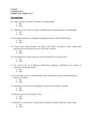
4 DETAILS FOR CONVENTIONAL WOOD FRAME CONSTRUCTIONtime of manufacture, producing mill number and the gradingrules writing agency.The bending strength, F b , and the stiffness or modulusof elasticity, E, may be determined from the grade mark forlumber used as joists, rafters, and decking. These valuesenable determination of allowable spans for the lumber.Grading rules for various softwood and certain hardwoodspecies are written by regional rules writingagencies, which operate within the system, established bythe <strong>American</strong> Lumber Standards Committee (ALSC) underthe authority of the U.S. Department of Commerce.This system provides for on-going inspection of lumberproduced to the applicable rules and for monitoring of theinspection agencies by the Board of Review of the ALSC.Engineering values and tables of allowable spans forframing lumber are available from the <strong>American</strong> Forest& Paper Association (Appendix, Items 3 and 4), and theregional rules writing agencies.LUMBER SEASONING<strong>Wood</strong> loses moisture from the time it is cut and manufacturedinto lumber until it reaches equilibrium in service.Best performance of wood frame buildings is obtained whenthe moisture content of framing lumber at the time the buildingis enclosed with sheathing and interior finish, is as closeas possible to the condition it will reach in service.Grading rules which conform with <strong>American</strong> SoftwoodLumber Standard, PS 20, provide for framing lumbersurfaced to standard sizes at the unseasoned condition (S-Grn), at 19 percent maximum moisture content (S-Dry)and at 15 percent maximum moisture content (KD) or(MC-lS). Standard sizes apply to S-Dry (19% max), withslightly larger sizes provided for S-Grn so that both productsreach approximately the same size after seasoning inservice. MC-lS lumber is produced to the same standardsize as S-Dry. In some cases engineering stress values assignedto lumber produced to different seasoningconditions are adjusted to reflect the effects of seasoning.Lumber should be protected from weather at the jobsite. Buildings should be roofed and enclosed with sheathingwithout delay to maintain the original dryness of thelumber or to help unseasoned lumber reach equilibriumduring construction.Final moisture content of lumber in the building varieswith the geographic region and with location in the structure.Floor joists over a crawl space may reach seasonalmoisture contents in excess of 14 percent. Roof trusses andrafters, on the other hand, may dry below 6 percent. Squeakingfloors and loose nails in wallboard or siding can bereduced by allowing framing to season to a moisture contentwhich is as close as possible to moisture levels it willreach in service and by utilizing modem framing techniquesand products, including glued-nailed floor systems, groovedor ring-shanked nails, and drywall screws.Protection of MaterialsLumber, panel products and millwork (windows, doorsand trim) should be protected from the weather when deliveredat the building site. Preparation of a constructionschedule will assure that lumber and millwork are deliveredas needed. Follow these simple rules:(1) Support framing lumber, plywood and panel productsat least six inches above ground and protectthem below and above with a waterproof cover suchas plastic film. Finish lumber and flooring, particularly,are to be protected from ground or concreteslab moisture and kept under cover - preferably indoors- until installation.(2) Store door and window assemblies, siding and exteriortrim inside. Where this is not practical, thesematerials are to be elevated from the ground andprotected above and below with a weatherproofcover.Millwork items are often pre-treated with a waterrepellentpreservative as received. Whether treatedor not, such materials are to be stored under cover.Untreated exterior millwork should receive a water-repellentpreservative treatment beforeinstallation.(3) Store interior doors, trim, flooring and cabinetworkin the building. Where wet plaster is used it must bepermitted to dry before interior woodwork, cabinetryand flooring are installed.TYPES OF FRAME CONSTRUCTIONPLATFORM FRAMEIn platform-frame construction, first floor joists arecompletely covered with sub-flooring to form a platformupon which exterior walls and interior partitions areerected. This is the type of construction most generallyused in home building, Figure 1.Platform construction is easy to erect. It provides awork surface at each floor level and is readily adapted tovarious methods of prefabrication. In platform systems it
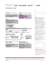
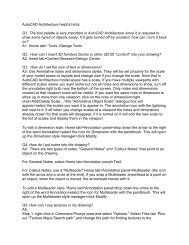
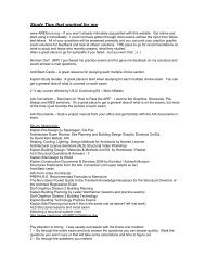
WOOD CONSTRUCTION DATA 1 5is common practice to assemble wall framing on the floorand tilt the entire unit into place.BALLOON FRAMEIn balloon-frame construction, exterior wall studs continuethrough the first and second stories. First floor joists andexterior wall studs both bear on the anchored sill, Figure 2.Second-floor joists bear on a minimum lx4-inch ribbon strip,which has been let-in to the inside edges of exterior wall studs.In two-story buildings with brick or stone veneer exteriors,balloon framing reduces variations in settlement offraming and the masonry veneer. Where exterior walls areof solid masonry, balloon framing of interior bearing partitionsalso reduces distortions in door and closet openingsin crosswalls. The requirement for longer studs, and thedifficulty in accommodating current erection practices andfirestopping, has reduced the popularity of this system.FASTENINGSNails, used alone or in combination with metal framinganchors and construction adhesives, are the mostcommon method of fastening 1- and 2-inch framing lumberand sheathing panels, Figure 4. Ring or spiral shanknails provide higher load-carrying capacities than commonnails of the same diameter, and are particularly usefulwhere greater withdrawal resistance is required.Nailed joints provide best performance where the loadacts at right angles to the nails. Nailed joints with the loadapplied parallel to the nail (in withdrawal) should beavoided wherever possible, since joints are weakest whennailed in this manner, Figure 3.Where tilt-up wall framing is not practical, or wherestronger stud-to-plate attachment is required (as in the useof rigid foam sheathing), toe-nailing is the most practicalmethod of framing studs and plates.In toe-nailing, nails are driven at a 30-degree angle(approximately) to the stud. Studs can be pre-drilled tosimplify this operation and prevent excessive splitting.PLANK AND BEAM CONSTRUCTIONIn the plank and beam framing method, beams of adequatesize to support floor and roof loads are spaced upto eight feet apart. Floors and roofs are covered with 2-inch planks. These serve as subflooring and roof sheathing,and, where tongue-and-grooved planking is used, providean attractive finished floor and ceiling.Ends of floor and roof beams are supported on postswhich provide the wall framing. Supplementary framingbetween posts permits attachment of wall sheathing andexterior sidings. Details for this method of framing are providedin Plank and Beam Framingfor Residential Buildings- <strong>Wood</strong> Construction Data No.4, published by the <strong>American</strong>Forest & Paper Association (Appendix, Item 5).TRUSS-FRAMEDCONSTRUCTIONThe strength and resilience of wood construction isdue to its framework of structural lumber combined witha covering of subflooring, wall and roof sheathing. Additionalengineering of the system through use of floor androof trusses and metal framing anchors provides evengreater rigidity and permits wider spacing of floor androof supporting members.FOUNDATIONSA firm foundation, consisting of properly installedfootings of adequate size to support the structure, is essentialto the satisfactory performance of all buildings.Such foundations fully utilize the strength and resilienceof wood frame construction.Footings should extend below exterior grade sufficientlyto be free of frost action during winter months. Whereroots of trees are removed during excavation or when buildingon filled ground, the ground should be well compactedbefore footings are installed or concrete is poured.Where poor soil conditions exist, satisfactory foundationsmay be constructed of treated tirnber piles cappedwith wood or concrete sills. Footing requirements are coveredin the local building code. It is good practice,generally, to make the footing thickness equal to the thicknessof the foundation wall and the footing projection equalto one-half the foundation wall thickness.Two principal foundation types are commonly used.These are concrete and pressure preservative treated wood.Concrete footings with poured concrete or masonry blockfoundation walls are most common. An increasingly popularfoundation for houses and other wood frame buildingsis the "Permanent <strong>Wood</strong> Foundation" which is acceptedby all model building codes and the Department of Housingand Urban Development (HUD).Concrete FoundationsConcrete footings are frequently unreinforced. Whereunstable soil conditions exist, however, reinforced concreteis used. This requires engineering analysis of thefooting. The foundation wall may be of poured concreteor masonry blocks. Masonry block basement walls typicallyhave a ~-inch coat of Portland cement mortar appliedto the exterior. When set, the mortar parging is coveredwith two coats of asphalt to resist penetration of the wall
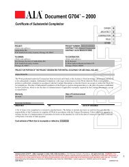
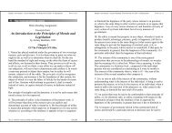
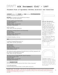
,6 DETAILS FOR CONVENTIONAL WOOD FRAME CONSTRUCTIONby ground water, Figure 5. Masonry block walls arecapped at the top with 4 inches of solid masonry or concrete.Drain tiles are installed around the entire footingperimeter of concrete foundations. These lead to a stormdrain or sump with pump to a positive drain.<strong>Wood</strong> FoundationsPermanent wood foundations are engineered systemsconsisting of wood framing and plywood sheathing thathave been pressure treated with heavy concentrations ofpreservative to assure freedom from decay and insect attack.The system is used with both basement and crawlspace foundations, Figures 6a and 6b.Permanent wood foundations are particularly suitablefor cold weather construction where the entire foundationsystem can be prefabricated. The footing and basementarea consists of a layer of gravel or crushed stone of 4-inch minimum thickness. Treated wood footing plates ofadequate thickness and width are placed on the stone baseat the wall perimeter. These support foundation stud wallsof treated lumber framing and plywood sheathing whichhave been designed to support vertical and lateral loads.Exterior plywood joints are caulked and basement foundationwalls are covered with 6-mil polyethylene film todirect ground water to the gravel base. Basement floorsare concrete slab or wood flooring laid on treated woodjoists on sleepers. A 6-mil polyethylene film is placed overthe gravel base beneath the slab or wood floor.Drain tiles are not required with permanent wood foundations.Ground water at the wall perimeter drains throughthe gravel footing and the gravel slab base to a sump whichleads to a daylight outlet or is pumped to a storm drain,Figure 7. Such basements have a superior record for maintainingdry interior conditions. Additional information onPermanent <strong>Wood</strong> Foundations is available from AF&PA andthe Southern Pine <strong>Council</strong> (Appendix, Items 6 and 7).Other FoundationsOther foundation types include free standing piers,piers with curtain walls, or piers supporting grade beams.Piers and their footings must be of adequate size to carrythe weight of the house, contents and occupants. Pier spacingwill depend upon arrangement of floor framing andlocation of bearing walls and partitions. Spacing in therange of 8 to 12 feet is common practice, Figure 8.PROTECTION AGAINST TERMITESDECAYANDGood construction practice prevents conditions thatcould lead to decay or termite attack. Details for termiteand decay prevention are found in Design of <strong>Wood</strong> Structuresfor Permanence-<strong>Wood</strong> Construction Data No.6(Appendix, Item 8). The following practices are basic:All roots and scraps of lumber are removed from theimmediate vicinity of the house before backfilling.Loose backfill is carefully tamped to reduce settlementaround the foundation perimeter. Grading at thefoundation and over the building site is sloped to providedrainage away from the structure.Unexcavated SpacesExposed ground in crawl spaces and under porches ordecks is covered with 6-mil polyethylene film. Minimumclearance between the ground and the bottom edge of beamsor girders is at least twelve inches. Clearance between thebottom of wood joists or a structural plank floor and theground is a minimum of 18 inches, Figure 9. Where it isnot possible to maintain these clearances, approved! pressuretreated or naturally durable wood species are used.Columns and PostsPosts or columns in basements and cellars, or exposedto the weather, are supported by concrete piers or pedestalsprojecting at least 1 inch above concrete floors or decksand 6 inches above exposed earth. <strong>Wood</strong> posts and columnsare separated from concrete piers by an imperviousmoisture barrier, except when approved pressure treated ornaturally durable wood species are used, Figures 9 and 10.<strong>Wood</strong> posts or columns which are closer than 8 inchesto exposed ground in crawl spaces or supporting porchesor decks are of approved pressure treated or naturally durablewood species.Exterior walls<strong>Wood</strong> framing and sheathing used in exterior wallsare installed at least 8 inches above exposed earth (includingfinished grade), unless approved pressure treatedor naturally durable wood species are used, Figures 11and 12.Beams and Girders in Masonry WallsOpenings or cavities in masonry walls to support theends of beams, girders, or floor joists are of sufficient size toprovide a minimum of Y2-inchclearance at the top, sides andends of such members, unless pressure preservative treatedor naturally durable wood species are used, Figure 12.<strong>Wood</strong> Supports Embedded in Ground<strong>Wood</strong> supports embedded in the ground to supportpermanent structures shall be treated with approved pressurepreservative treatments. <strong>Wood</strong> posts, poles andcolumns which support permanent structures and which!Approved, as used in this text, means approved by the authority having jurisdiction.
WOOD CONSTRUCTION DATA 1 7are embedded in concrete in direct contact with earth orexposed to the weather, shall be treated with approvedpressure preservative treatments.SidingA minimum clearance of 6 inches is maintained betweenthe finished grade and the bottom edge of all typesof siding used with wood frame buildings. Such clearancepermits ready inspection for termite activity andimproved performance of exterior paint and stain finishes.Crawl Space VentilationCrawl spaces are vented by openings in foundationwalls. The number and size of such vent openings are determinedto provide a minimum total vent area equal to1/150 of the crawl space ground area. For example, a 1500sq. ft. ground area would require a total of 10 sq. ft. ofvented opening, or 10 vents, each 1 square foot in netopening size. Corrosion resistant mesh with lA-inch maximumopenings is recommended.A 6-mil plastic film ground cover in the crawl spacereduces the required amount of ventilation to 10 percentof the preceding recommendation. With ground coverprotection, vents may have operable louvers. Vent openingsshould be placed to provide cross ventilation andoccur within 3 feet of comers.Termite ControlAfter removal of all scrap wood from the buildingperimeter, treatment of the soil around the foundation withan approved termiticide is the most effective protectionagainst subterranean termites. Properly installed termiteshields also provide protection where the interiors of foundationwalls are not easily inspected, Figure 13.Additional RequirementsIn geographical areas where experience has demonstrateda need for more protective measures, therequirements of the preceding paragraphs may be modifiedto the extent required by local conditions.FLOOR FRAMINGFloor framing consists of a system of sills, girders,joists or floor trusses and sub-flooring that provides supportfor floor loads and gives lateral support to exteriorwalls.Sills on Foundation WallsSills resting on continuous masonry foundation wallsare generally of nominal 2x4 or 2x6 lumber. They are anchoredto masonry walls with Y2-inch bolts atapproximately 6-foot intervals. Bolts are embedded at least6 inches in poured concrete walls and at least 15 inches inmasonry block walls, Figure 14. Metal anchor straps,embedded in foundation walls at sufficient intervals topermit adequate nail fastening to sills, may also be used.Sills on PiersSills supported by free-standing piers must be of adequatesize to carry all imposed loads between piers. Theymay be of solid wood or of built-up construction such asdescribed for beams and girders. Sills are anchored to pierswith Y2-inch bolts embedded at least 6 inches in pouredconcrete and at least 15 inches in masonry block, Figure 8.Beams and GirdersBeams and girders are of solid timber or built-up constructionin which multiple pieces of nominal2-inch thicklumber are nailed together with the wide faces vertical.Such pieces are nailed with two rows of 20d nails-onerow near the top edge and the other near the bottom edge.Nails in each row are spaced 32 inches apart. End jointsof the nailed lumber should occur over the supportingcolumn or pier. End joints in adjacent pieces should be atleast 16 inches apart, Figure 15. Glued-laminated membersare also used. Beams and girders that are notcontinuous are tied together across supports. Bearing ofat least 4 inches is required at supports.Selection and Placing of JoistsSpan Tables/or Joists andRafters (Appendix, Item 4)published by the <strong>American</strong> Forest & Paper Association,provides maximum allowable spans for the different speciesand grades of lumber depending upon floor and roofdesign loads and spacing of the members.Joist end-bearing should not be less than 1Y2incheson wood or metal and 3 inches on masonry. Joists are usuallyattached to sills by two toe-nails, or by metal framinganchors, Figures 8, 11 and 16. Joists should be placed sothe top edge provides an even plane for the sub-floor andfinished floor. It is preferable to frame joists into the sidesof girders to reduce the cumulative effect of seasoningshrinkage, Figures 17, 18, 19 and 20.BridgingAdequately nailed subflooring will maintain the upperedges of floor joists in proper alignment. Nailing theends of joists to band joists or headers, Figures 11 and24, provides additional joist support that, under normalconditions, eliminates the need for intermediate bridging.Where the nominal depth-to-thickness ratio of joists exceeds6, or where builders have encountered problemswith twisting of joists in service, intermediate joist bridg-
8 DETAILS FOR CONVENTIONAL WOOD FRAME CONSTRUCTIONing is installed at 8-foot intervals. Bridging may also beaccomplished with cross braces of nominal Ix4-inch lumberor solid 2-inch lumber, Figures 21 and 22.Framing of Floor OpeningsHeaders, trimmers and tail joists form the framing forfloor openings. Trimmers and headers are doubled whenthe header span exceeds 4 feet. Headers more than 6 feetin length are supported at the ends by joist hangers orframing anchors unless they are bearing on a partition,beam or wall. Tail joists which exceed 12 feet in lengthare supported on framing anchors or on ledger strips notless than nominal 2x2 inches, Figures 23, 24 and 25.Notching and Boring of JoistsNotches or holes in joists for plumbing or wiring shallnot be cut in the middle one-third of the joist span. Notchesin the outer-third sections of the span may be no greaterthan one-sixth the joist depth. Where notches are made atthe joist ends for ledger support, they may be no greaterthan one-fourth the joist depth. Holes in the outer-thirdjoist sections are limited in diameter to one-third the joistdepth and are cut with the edge of the hole no closer than2 inches to the top or bottom edges, Figure 26.Support of PartitionsBearing partitions are normally placed over girdersor walls which support the floor system. Where floor framingis adequate to support the added load, bearing partitionsmay be offset from supporting members by no more thanthe joist depth, unless floor joists are designed to carrythe increased load, Figures 27 and 28.Where non-bearing partitions run parallel to floorjoists, the joist under the partition is doubled to supportincreased loads which frequently occur adjacent to thepartition, Figures 29 and 30.Overhang of FloorsWhere second-floor joists project over the first storywall at right angles, they are cantilevered to support thesecond story wall, Figure 35. Where the overhanging wallis parallel to the second floor joists, a double joist supportslookout joists which extend at right angles over thefirst story wall, Figure 36. The double joist is locatedinside the supporting wall at a distance equal to twice theoverhang. Lookout joists are framed into the double joistby framing anchors or a ledger strip nailed at the upperedge.FIRESTOPPINGAll concealed spaces in wood framing are frrestoppedwith wood blocking or other approved materials. Blockingmust be accurately fitted to fill the opening and toprevent drafts between spaces, Figures 2, 16, 27, 28,31,and 32.Openings around vents, pipes, ducts, chimneys, fireplacesand similar fixtures which would allow passage offire are filled with non-combustible material, Figure 37.Other firestopping requires 2-inch lumber or twothicknesses of l-inch lumber with staggered joints, or onethickness of ¥I-inch plywood with joints backed by l-inchlumber or ¥I-inch plywood.Sills and plates normally provide adequatefirestopping in walls and partitions. However, stopping isrequired at all intersections between vertical and horizontalspaces such as occur at soffits, dropped ceilings andcoved ceilings, Figure 38.Furred spaces on masonry walls are firestopped at eachfloor level and at the ceiling level by wood blocking or bynon-combustible material of sufficient thickness to fill thespace, Figure 39.DRAFTSTOPPINGIn single family residences, draftstopping is requiredparallel to main framing members in floor/ceiling assembliesseparating usable spaces into two or moreapproximately equal areas with no area greater than 500square feet. Materials for draftstopping may be 3/8-inchplywood or Y2-inchgypsum board, Figure 40.EXTERIOR WALL FRAMINGExterior wall framing must be of adequate size andstrength to support floor and roof loads. Walls must alsoresist lateral wind loads and, in some locations, earthquakeforces. Top plates are doubled and lapped at corners andat bearing partition intersections to tie the building into astrong structural unit. A single top plate may be used whereroof rafters or trusses bear directly above wall studs. Insuch cases adequate corner ties are required, particularlywhere non-structural sheathing is used.Stud Size and SpacingStuds in exterior walls of one and two-story buildingsare at least norninal2x4 inches with the 4-inch dimensionforming the basic wall thickness. Stud spacing is normally16 inches in exterior walls, although 24-inch spacing of2x4 studs is acceptable in one-story buildings if wallsheathing or siding is of adequate thickness to bridge
WOOD CONSTRUCTION DATA 1 9across studs. In three-story buildings studs in the bottomstory are at least nominal 3x4 or 2x6 inches and may notexceed 16-inch spacing.Studs are arranged in multiples at comers and partitionintersections to provide for rigid attachment ofsheathing, siding and interior wall finish materials. Nailingstrips or metal clips may be used to back up interiorfinish at comers, Figures 41 and 42.Exterior Wall OpeningsA header of adequate size is required at window anddoor openings to carry vertical loads across the opening.Headers may be supported by doubled studs or, where thespan does not exceed 3 feet, framing anchors may be usedwith single supporting studs, Figures 43 and 44. Wherethe opening width exceeds 6 feet, triple studs are usedwith each end of the header bearing on two studs.Gable End WallsStuds at gable ends bear on the top plate and arenotched and nailed to the end rafter, Figure 46.Wall SheathingThe high resistance of wood frame construction tohurricane, earthquake and other forces of nature is providedwhen wood sheathing is adequately nailed to theoutside edges of exterior wall studs, plates and headers.Wall sheathing includes plywood, particleboard and otherstructural panels such as wafer-board, oriented-strandboard, structural insulation board and one-inch board lumber.Such sheathing is applied in strict accordance withmanufacturer's nailing requirements to provide a rigid,yet resilient, wood frame system. Some structural panelsfunction as both sheathing and siding.Where the building exterior is to be stuccoed, whereplastic foam sheathing is used, or where bevel or otherlap siding is applied directly to the studs, exterior wallsmust be braced at the comers with 1x4 lumber which hasbeen "let-in" to the outside surfaces of studs, plates andheaders at an angle of 45 degrees, Figures 1 and 2. Metalstrap braces adequately nailed may be used. Plywood orother structural panels applied vertically at each comeralso serve as adequate corner bracing where non-structuralsheathing is otherwise used.Building or Sheathing PaperWalls are protected from wind and water infiltrationby covering the wall sheathing with a layer of Type 15asphalt saturated felt paper or with other suitable waterrepellent paper or plastic films. Such coverings must permitpassage of any moisture vapor which enters the wallsystem from the interior and have a vapor permeabilityrating of five or greater. Six-inch wide strips of sheathingpaper are applied around all wall openings and behind allexterior trim, Figures 49 and 50. Sheathing paper is appliedfrom the bottom of the wall, lapping horizontal joints4 inches and vertical joints 6 inches.INTERIOR PARTITION FRAMINGThere are two types of interior partitions: bearing partitionswhich support floors, ceilings or roofs; andnon-bearing partitions which carry only the weight of thematerials in the partition, including attachments in the finishedbuilding.Bearing PartitionsStuds in bearing partitions should be at least nominal2x4 inches, with the wide surface of the stud at right anglesto top and bottom plates or headers. Plates are lapped ortied into exterior walls at intersection points.Single top plates are permitted where joists or raftersare supported directly over bearing wall studs. Studs supportingfloors are spaced a maximum of 16 inches oncenter. Studs supporting ceilings may be spaced 24 incheson center. Headers in bearing walls are used to carry loadsover openings, as required for exterior walls.Non-Bearing PartitionsStuds in non-bearing partitions are nominal 2x3 or2x4 inches and may be installed with the wide face perpendicularor parallel to the wall surface. Single top platesare used. Stud spacing is 16-or 24-inches on center as requiredby the wall covering.FRAMING AROUND CHIMNEYSFIREPLACESANDFraming<strong>Wood</strong> framing must be adequately separated from fireplaceand chimney masonry, Figures 47a and 47b. Allheaders, beams, joists and studs must be kept at least twoinches from the outside face of chimney and fireplacemasonry. Prefabricated metal fireplace and chimney assembliesare to be installed in accordance with themanufacturer's recommendations and must be approvedby the code authority.Trim<strong>Wood</strong> mantles and similar trim are separated from fireplaceopenings by at least six inches, Figures 48a and 48b.Where combustible material is within 12 inches of thefireplace opening, the projection shall not exceed Y2 inchfor each I-inch distance from such opening.
10 DETAILS FOR CONVENTIONAL WOOD FRAME CONSTRUCTIONROOF AND CEILING FRAMINGRoof construction must be of adequate strength towithstand anticipated snow and wind loads. Framing membersmust be securely fastened to each other, to sheathingand to exterior walls to enable the roof system to serve asa structural unit, Figures 51 through 59.Ceiling Joist and Rafter FramingMaximum allowable spans for ceiling joists and raftersfor various lumber grades and species are provided in SpanTables for Joists and Rafters, (Appendix, Item 4).Ceiling joists must be securely nailed to exterior wallplates, to the ends of rafters and where the joists join overinterior partitions. This provides a structural tie across thebuilding to withstand outward forces exerted by the rafters,Figure 51. Ceiling joists at right angles to rafters are to beavoided, Figure 52.The ridge member is of 1- or 2-inch thick lumber andis 2 inches deeper than the depth of the rafters to permitfull bearing at the angled rafter ends. Rafters are placeddirectly opposite each other across the ridge and arenotched at the lower end to fit the exterior wall top plate,Figures 53 and 57. Rafters are secured to the wall plateby toe-nailing or use of special metal plate fastenings.Collar Beams (collar ties)Collar beams of nominal lx6 or 2x4 lumber are installedin the upper one-third of the attic space to everythird pair of rafters to secure the ridge framing.Valley and Hip Rafter FramingValley rafters at the intersection of two roof areas aredoubled in thickness and two inches deeper than adjoiningrafters, Figure 55.Hip rafters are of single thickness but are two inchesdeeper than common rafters to permit full bearing of jackrafters, Figure 56.Where ridges occur at different elevations, provisionmust be made for vertical support of the interior end ofthe lower ridge board.Roof TrussesRoof framing may be fabricated as light trusses andinstalled as complete units. Such framing is designed accordingto accepted engineering practice. The trussmembers are joined together by fasteners such as nails,nails and glue, bolts, metal plates or other framing devices.Use of roof trusses eliminates the need for interiorbearing partitions and frequently results in more rapid installationof roof and ceiling framing. Roof trusses aregenerally spaced 24 inches on center.Where roof trusses are used, gable ends are usuallyframed in the conventional manner using a common rafterto which gable end studs are nailed. Eave overhangs areframed by extending the top chords of the trusses beyondthe wall.Where hip and valley construction is required, modifiedtrusses or conventional framing are used to meet thecondition.Ceiling-Floor-Partition SeparationIn some localities truss uplift may be a problem. Thisproblem is characterized by the separation of the floor orceiling from an interior partition.A widely used technique to minimize truss uplift separationis to allow the gypsum board ceiling to "float" orrest on the partition and remain unattached to the truss oneither side ofthe partition. In cases where trusses are perpendicularto partitions, the gypsum board ceiling remainsunattached at least 18 inches from the ceiling! wall intersection,Figure 68. Additional solutions to this separationare found in two reports referenced in Appendix, Items12 and 13.Flat RoofsFlat roofs should be avoided if possible because theyare difficult to ventilate and insulate adequately and presentweather proofing problems. Where flat roofs are used,rafters or roof joists serve as ceiling joists for the spacebelow, Figure 54. Maximum allowable spans for ceilingjoists and rafters are contained in Span Tables for Joistsand Rafters, (Appendix, Item 4). Flat roof joists are securelynailed to exterior wall plates and to each other wherethey join over interior partitions.Roof Sheathing<strong>Wood</strong> structural panels or l-inch board lumber providesa solid base for roof coverings. Structural panelsare manufactured in various thicknesses and are usually4'x8' in surface dimension. Recommended spans, spacingbetween panel edges and thickness are stamped onthe panel face. Structural panels are installed with the longdimension perpendicular to rafters and with the panel continuousover two or more spans.Spaced SheathingWhere wood shingles or shakes are to be applied asthe finished roof, solid sheathing is used or nominallx4lumber is nailed perpendicular to rafters and trusses witheach board spaced a distance from the next board equal tothe weather exposure ofthe shingles or shakes. (5Y2inches
WOOD CONSTRUCTION DATA 1 11is common exposure for shingles. Shakes may be exposed7 to 13 inches depending on their length.) Because shakesare not smooth surfaced, an 18-inch wide underlay of asphaltfelt is used between each course. Where wind drivensnow is encountered, solid sheathing and Type 15 asphaltfelt are used under wood shakes.Ventilation of Attic SpacesVentilation of all attic spaces is required to eliminatemoisture condensation on roof framing in cold weatherand to permit heat to escape in warm weather, Figure 61.For gable roofs, a screened, louvered opening is usedwhich provides a net open area of 1/150 of the area of theceiling below. Where a %-inch wide screened slot is alsoprovided in the eave soffits, or where a vapor retarderhaving one perm or less permeability is installed on thewarm side of the ceiling, the total ventilating area may bereduced to 1/300 of the ceiling area.With hip roof construction, a %-inch wide screenedslot in the eave soffits, and ventilator at the ridge to provide1/450 inlet and 1/900 outlet fractions of the ceilingarea below, assures adequate ventilation.For flat roofs, blocking, bridging and insulation arearranged to prevent obstruction of air flow. Such roofsare ventilated at eave soffits to provide net open area equalto 1/250 of the area of the ceiling below. A vapor retarderof one perm or less permeability is applied under the ceilingfinish below flat roofs.INSULATION AND VAPOR RETARDERSInsulationAdequate insulation in stud spaces of exterior walls,between floor and ceiling joists or rafters and on the insideof masonry foundations between grade line and firstfloor, make wood frame construction efficient to heat andcool. It also increases occupant comfort and absorbs outsidenoises. Roll or batt-type insulation is installed fullthickness in exterior walls or between rafters. Roll or loosefill insulation is used in attics between ceiling joists. Rigidfoam plastic is bonded to the inside of foundation wallswith construction adhesive.Vapor RetardersVapor retardant film prevents moisture vapor frommoving through the insulated wall and condensing on theback side of sheathing and siding. Such condensationgreatly reduces the effectiveness of insulation and causesfailures of exterior paints and finishes.Wall insulation batts usually have vapor retardant papercovers facing the room interior. However, the mostcommon method of installing wall insulation batts ereatesgaps along each stud, which make this type of vaporprotection of little value. Proper vapor protection requiresa 4-mil (.004") minimum thickness of polyethylene filmstapled to wall studs immediately beneath the dry wall orother interior finish. The film is carefully fitted aroundwindow and door openings and behind electric outlets.Crawl spaces and basement concrete slabs are alsosources of moisture vapor, which reduce the effectivenessof insulation and create expansion problems with hardwoodflooring. A 6-mil (.006") polyethylene film placedover the ground in crawl spaces and over the gravel beforethe basement slab is poured is the most effectivemethod of controlling moisture vapor from the ground.Some plastic foam sheathings and foil-faced sheathingmay act as vapor retarders on the outside of exteriorwalls. Where such sheathing panels are used, it is essentialthat a vapor retardant polyethylene film be placed onthe inside wall surface, beneath the interior wall finish.EXTERIOR SIDING AND COVERINGSMany types of wood, hardboard, shingle, structuralpanel, metal and masonry veneer sidings are used overwood framing. Such materials are separated from the final,finished grade by a minimum of 6 inches, Figure 49.<strong>Wood</strong> SidingA variety of wood and hardboard siding patterns areavailable. Bevel, shiplap and drop types are generally usedhorizontally. Board-and-batten, board-on-board andtongued and grooved boards are applied vertically,Figure 63. Surfaces are smooth, rough sawn or overlaidwith paper or plastic film. They may be natural or factorypre-primed or pre-finished.Siding and exterior trim are applied over a layer ofType 15 asphalt felt or other water repellent sheathingcover with corrosion-resistant nails. Hot dipped galvanizedsteel, stainless steel or aluminum nails may be used. Naillength varies with the thickness of siding and sheathing.For smooth shank siding nails, required length is determinedby adding to the combined siding and sheathingthickness an additional Ivi inches for penetration into solidwood.Where foam sheathing or insulation board sheathingare used, "solid wood" means Ilh-inch nail penetrationinto the stud. However, where plywood, waferboard ororiented strand board sheathing are used, the thickness ofthese panels becomes a part of the Ilh-inch solid woodnail penetration.Ring-shank or spiral-shank siding nails have additionalholding power. A reduction of 1/8 to 1/4 inch in requirednail penetration into solid wood is permitted for these fas-
12 DETAILS FOR CONVENTIONAL WOOD FRAME CONSTRUCTIONteners. Additional requirements apply to use of rigidfoam plastic sheathing, and are published by AF&PA(Appendix, Item 9).Bevel siding and square edged boards applied horizontallyare nailed with a single nail at each stud. Theminimum lap is 1 inch, with the nail driven approximately1Y2inches above the lap, Figure 63(a).Drop and shiplap type sidings, which lay flush againstthe sheathing paper, are nailed at each stud with a singlenail approximately 1Y2inches above the drip edge. Wheresiding width is 8 inches or more or where sheathing isomitted, two nails are used, Figure 63(b).Comer treatment is governed by the house design.Comer boards, mitered comers, metal comer covers oralternately lapped comers are used, Figure 64.Board siding, both square edge and tongue andgrooved, is applied vertically, Figures 63(c) and 63( d).Where wood, plywood or structural panel sheathing ofY2-inch minimum thickness is used, nails are spaced 16inches vertically. For other types of sheathing, horizontalnominallx4-inch furring strips are applied at 24-inch intervalsas a nail base for vertical siding application. Wherestud spacing exceeds 16 inches, inter-stud blocking with2-inch lumber between studs is required.Protection of SidingEnds of wood siding at comers, butt joints and at jointswith window and door trim are protected by an applicationof clear water repellent preservative. Dipping at thetime of siding application or subsequent brush or spraytreatment before caulking and painting are effective.Where wood siding is to be left to weather unfinished, aliberal coat of clear water repellent preservative is appliedto the entire exterior siding surface.<strong>Wood</strong> Shingles and ShakesShingles and shakes used as exterior wall coveringare applied with the weather exposures in Table II.Shingles and shakes are nailed with corrosion resistantnails of sufficient length to penetrate wood sheathing.Two nails are used for widths up to 8 inches. For widershingles and shakes, three nails are used.With single course applications nails are driven oneinch above the butt line of the succeeding course. In doublecoursing the under course is attached to wood sheathingwith three nails or staples. The outer course is appliedwith small-headed nails driven approximately 1 inch abovethe butts and % inch from the edges.Where other than wood, plywood, waferboard or oriented-strandboard sheathing is used, a nail base oflx3-inch wood furring strips is applied horizontally at intervalsequal to the weather exposure of the shingles orshakes, Figure 50.Masonry VeneerMasonry veneer applied to wood frame constructionis supported on the masonry foundation wall. Where permanentwood foundations are used, masonry veneer issupported on the preservative treated wood footing plateor on a preservative treated wood knee wall attached tothe wood foundation with corrosion resistant metal ties.Ties are spaced horizontally 24 inches on center, with eachtie supporting no more than two square feet of wall area.Ties are fastened through sheathing directly to foundationstuds, Figure 65.In masonry veneer applications to permanent woodfoundations, a l-inch space is left between sheathing andmasonry. Base flashing extends from the outside face ofthe masonry wall over the foundation and up the sheathinga minimum distance of 12 inches. Weep holes areprovided by leaving open vertical joints at 4-foot intervalsin the bottom course of masonry veneer.FLOORINGFlooring consists of the subfloor, underlayment and finishfloor. Depending upon the type of finish floor or subfloorused, underlayment may not be required. Where 25/32-inchtongue and grooved wood strip flooring is used, it may belaid directly over the subfloor, Figure 66. Where lesserthicknesses of wood strip flooring are used, the thicknessand grade of subflooring must be adequate to support endjoints at full design load, unless they occur over joists.Underlayment is normally applied over the sub-floorwhere resilient tile, sheet vinyl or carpet is used as thefinish floor surface.Sub-flooringThe sub-floor usually consists of plywood, particleboardor other wood structural panels, or board lumber.Lumber sub-flooring is typically laid diagonally to permitwood strip finish flooring to be laid either parallelwith or at right angles to, the floor joists. End-joints insub-flooring are cut to occur over joists.<strong>Wood</strong> structural panels are typically installed with thelong dimension at right angles to the joists and with thepanel continuous over two or more spans. Spacing betweenpanels should be approximately 1/8 inch.UnderlaymentUnderlayment panels are applied over sub-flooringto provide a smooth surface for application of carpetingand other resilient floor coverings. Plywood underlayment
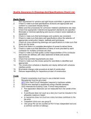
WOOD CONSTRUCTION DATA 1 13requirements are covered by U.S. Product Standard PS 1-95, which is published by APA-The Engineered <strong>Wood</strong>Association (Appendix, Item 10). Hardboardunderlayment requirements are set forth in ANSI! AHAA135.4 (Appendix, Item 11)published by the <strong>American</strong>Hardboard Association. Application of finish floor coveringsis generally by specialists who follow themanufacturer's installation instructions for the carpet, resilienttile or vinyl products.<strong>Wood</strong> FlooringHardwood and softwood strip flooring of %-inch or25/32-inch thickness provides adequate strength and stiffnessfor direct application over sub-flooring at right anglesto joists. Where parquet (squares) are used or where stripflooring is laid parallel to joists, the grade and thicknessof sub-flooring panels must be adequate to provide supportbetween joists. An additional thickness of subflooringmay be required over the rough subfloor in such applications.<strong>Wood</strong> strip flooring is normally applied over buildingpaper and is sanded and fmished after installation. Anexpansion joint of at least one-half inch must be providedat the edge of flooring strips adjacent to parallel partitionsand exterior walls. This joint is covered by thebaseplate and toe molding.WOOD DECKS<strong>Wood</strong> decks are a special feature of many new housesand a useful add-on to others. Their capability for providingadditional low-cost living and recreational space makesit important to consider them as part of the original housedesign. Use of pressure treated and naturally durable lumberhas made these outdoor structures as permanent asthe house itself.Supporting joists, posts and decking lumber must beproperly grade marked and identified as naturally durableor pressure preservative treated wood by quality controlagencies approved by the model building codes or thedwelling codes.DesignDeck shape and size should be consistent with thegeneral lines of the house and should be positioned to functionas part of the total structure. Orientation for sunexposure and shade is particularly important in locationof the deck.EngineeringCantilevered and other special deck types should beproperly engineered. Forty pounds per square foot is aminimum design live load, considering the concentrationof people frequently supported by decks. The applicablecode will govern this requirement.The initial header joist for the deck is attached to aband or header joist of the house with through bolts or lagscrews, Figure 67. The level of the deck framing, includingthe Ph-inch decking thickness is determined so thatthe deck surface is at least one inch below that of the interiorfloor surface. If deck height is significantly differentfrom that of the band or header joists of the house, thedeck header must be securely fastened to the wall studs.Joists are attached to the header by proper toe-nailing,preferably, by metal hangers to prevent splitting. Corrosionresistant hangers and hot-dipped galvanized orstainless steel nails are required.Post lengths are determined after deck framing hasbeen supported on temporary 2x4 posts. For posts, pressurepreservative treated for ground contact, footing holesare dug at required points. Concrete or gravel bases of 4-inch minimum thickness below the frost line are placedover compacted soil in the holes. From the concrete orgravel base required length of post to the deck level canbe determined.Footings for naturally durable wood posts extend 6inches above grade. Pre-cast concrete piers or concreteblock piers with imbedded Y2-inchre-enforcing bar pinsor treated wood nailers are used to secure posts againstlateral movement, Figure 67.DeckingThe floor of the deck is normally 2x4-inch or 2x6-inch lumber. It is nailed with the end-grain showing the"bark-side-up." Where pressure preservative treated lumberor unseasoned naturally durable lumber species areused, decking pieces can be nailed in contact or spaced nofarther apart than a nail diameter. Kiln dried decking canbe laid with a maximum spacing of lA-inch.Decking nails must be good quality hot-dipped galvanized,aluminum or stainless steel. Two 16d nails aredriven at slight angles to each other at each joist position,Figure 67. Butt joints in 2x6 decking require three nails.RailingsRailing designs follow the style of the house. Railingsmust be securely anchored to the deck, preferablyincluding an extension of the posts. Openings in the railingare limited to six inches, or as the code requires.FinishesBoth pressure treated and naturally durable wood areresistant to decay and insects. However, a good waterrepellentstain or paint finish will protect against checking
14 DETAILS FOR CONVENTIONAL WOOD FRAME CONSTRUCTIONand maintain the attractiveness of the deck. Applicationof a clear water repellent preservative immediately uponcompletion of the deck is recommended for both pressuretreated and naturally durable lumber.CONCLUSIONThe home is, for many families, the major investmentof a lifetime. While, in a mobile society, many familieswill have lived in several homes, each structure shouldserve as a prized possession, capable of providing comfortableshelter for a succession of satisfied occupants.Basic house construction follows simple engineeringprinciples. In addition, the workmanship of the home,which involves carpentry and a number of other constructiontrades, is in many ways a truly <strong>American</strong> art-form.This publication provides essential requirements for construction,and information to assist in the design,construction and inspection of wood structures of provendurability and performance.
18 DETAilS FOR CONVENTIONAL WOOD FRAME CONSTRUCTIONFigure 2.Balloon Frame Construction6UBFLOORtN6-'"." '.'- -,,:~'.' '. .... .Figure 3.Methods of Loading Nails+-ct±---
WOOD CONSTRUCTION DATA 1. 1.9Figure 4.Sizes of Common Wire NailsGAG£2 ~~~.~~~~~~~~~~~;~d3~~. ~~~~~~~~~~~~~~l!>~4 ~~~~~'~~~1~· ~~~~~~~~~~~~~.~~40d50d5 ~~~mm~ ... ~··.~· ~~~~~~~~~~.~.30d8 ~m.9 ~~19 ~~Pj~W~'~~~~~~~~~~~IOY4 ~IOY4ItY212~ ~ 4~, I II~~9dIOd··rbd-c-,.1···'.. .. : . ... 6Note: Print to scale to ensure accurate measurements. Do NOT check "Fit to Page."f2d.~ad1r~1l.~s.§~~~~~~~~~~a •••qII~ t)mm··· .12Yz~BE5d6d7d~
20 DETAILS FOR CONVENTIONAL WOOD FRAME CONSTRUCTIONFigure 5.Masonry Foundation Wall and FootingFigure 6a. Permanent <strong>Wood</strong> Foundation - Crawl space----t~t--~FI..OORJOISTT-I---~~li~h!---F1ELDAPPLIED 2.1C_TOPPLA.i€1l.LI.I.Ll~~-2)(_lOP PLA-re16"MINe"MI~~-PLVWOOPZ"'-"FINI5HED GRADe" SLOPE Yz." PER
WOOD CONSTRUCTION DATA 1 21Figure 6b. Permanent<strong>Wood</strong> Foundation - BasementPRESSURE'1'REAT~DWOOVNOTE~ S~E G-ENERALN0155 fORPERMISSIBLE VARlA1lDNb.FLOOR JOl5iFL..A~ING-PL'IWODD MAY OVERLAP FIEU>AppL.n~p '"TOP PLATE fOR SHE:AR TJW.l!>F~R~~-~,..... fiELD APPUED 2.)(_ TOP PLATe:-~:mkt~I---I2.)C- TOP PLATE'ULK.FINISH GRAPE" 5LOP£~~~\~MIN. (0' fROM WALL...yz:' PER roark----2.x__ STUDWALLOPTIONAL INTeRIORfl~HSH,,\..,Hh!¥j+!:il!-~~-IN5ULAT\£».lAfJ APPROPR'~"E1)(_ OR. pLXwOOD STRIP PROTEC-ilNCfrop OF roL.YEfH'f'LE:N e: FI LtI.\~ ~ PL'{w'OOD1I1~.lJJ\~/(J D 00 ~A6PHAL.--r OR POL.iE:THil£NE" flL.M STRIPG{L-~--~,u)~l.----,4"OR ¥ (.l)NGR€'f~ SL.Af>GRAVELOf{GRU~e:D 51t>NE"A~1J{1J~-I":_ sc,REf.D BOARD (DP110~L)1t-fl-6o'----PDLYE1H'(LENEFILM~"'--:-=:=:"----_y._ t;OTlOM PLATe:~~~~===+2 )(_ fOon NG- PLATe
22 DETAILS FOR CONVENTIONAL WOOD FRAME CONSTRUCTIONFigure 7a. Sump for Poorly Drained SoilsN07E: 1. USE Or SUMP PUMP IS OPTIONAL.2. 24 INCff f)IAMtJER. OR..20 INCff SQUAl?,£. 7El?J?/!COTTA TlLf. 0R..l7?JYr7ED WOOf) BOX MAr BESUBSTITU7ED TOR..?R..t.CASTCONCR.t-lE TlLf.., .. _ ..: .':.Yo ._ •••••., : ••.. '11."', •. : y ",; p#~'.~;"'.: .... : #'' •• 7' ".• ~:": .~v.. ., e eo"•••.-----------if'rti~- Z4' DIAMere~ P£E
WOOD CONSTRUCTION DATA 1 23Figure 8.Pier Foundation andAnchorageFigure 9.Clearance Between Earthand Floor FramingFigure 10. Support for BasementPostWOOl>POSTMOISTURE eARR! Ell.. &E1"WEeN WOODPo",,, ANt) a>Nc~E"~QE!>"AL.
24 DETAILS FOR CONVENTIONAL WOOD FRAME CONSTRUCTIONFigure 11. Floor Framing at ExteriorWallFigure 12. Girder Framing in ExteriorWallFigure 13. Termite Shields
WOOD CONSTRUCTION DATA 1 25Figure 14. Anchorage of Sill toFoundation WallFigure 15. Nailing Built-up Beams andGirdersEND JOINT..•tJAIL.S32."1POSTPOSTFigure 16. Joist End BearingFI~5"'OPPING',
26 DETAILS FOR CONVENTIONAL WOOD FRAME CONSTRUCTIONFigure 17. Joist Supported on LedgerFigure 18. Joist Supported by MetalFraming AnchorsFigure 19. Joists Resting on GirderFigure 20. Joists Resting on SteelBeam
WOOD CONSTRUCTION DATA 1 27Figure 21. Diagonal Bridging of Floor JoistsFigure 22. Solid Bridging of Floor JoistsSOI,....ID~R.l DG ING
'28 DETAILS FOR CONVENTIONAL WOOD FRAME CONSTRUCTIONFigure 23. Framing of Tail Joists onLedger StripFigure 24. Framing of Tail Joists byFraming AnchorsFigure 25. Framing of Header toTrimmer by Joist HangersFigure 26. Notching and Boring ofJoists
----------------------- -WOOD CONSTRUCTION DATA :1 29Figure 27. Framing Over BearingPartition, PlatformConstruction,sTUD
30 DETAILS FOR CONVENTIONAL WOOD FRAME CONSTRUCTIONFigure 29. Framing Under Non-Bearing PartitionFigure 30. Attachment of Non-Bearing Partition to Ceiling FramingNA\LERSINGLETOPPL~"'£"~TUD.,/
WOOD CONSTRUCTION DATA 1 31Figure 31. Interior StairwayFramingSUBFLOORIN(1FlREf>TOPPING-
32 DETAILS FOR CONVENTIONAL WOOD FRAME CONSTRUCTIONFigure 32. Stairway With a LandingFII~£('TOPPI HIi'Figure 33. Framing SupportingBathtubBLOc.K:
WOOD CONSTRUCTION DATA 1 33Figure 34. Second Floor Framing,Exterior WallFigure 35. Second Floor Overhang ofExterior Wall, Joists atRight Angles toSupporting WallsFigure 36. Second Floor Overhang ofExterior Wall, JoistsParallel to SupportingWalls
34 DETAILS FOR CONVENTIONAL WOOD FRAME CONSTRUCTIONFigure 37. Firestopping Around PipesNON-C.OM&! 5TI6L.E"FIRE".5TOPFigure 38. Firestopping of Dropped CeilingsFIRE'STOPPING-
WOOD CONSTRUCTION DATA 1 35Figure 39a.Firestopping of Masonry Walls - FloorNON- C.OMBUST' SL.E"FIRE5TOP ---Figure 39b.Firestopping of Masonry Walls - CeilingNON-COMe>USTl8l,.t:.FIR-ESTOP
36 DETAILS FOR CONVENTIONAL WOOD FRAME CONSTRUCTIONFigure 40. Draftstoppingof Trussed Floors1>RAfTSTOPPlNG-.....-, J~ FL.ooR TRUSSFigure 41. Multiple Studs at CornersFigure 42. Wall Framing atIntersecting Partitions
WOOD CONSTRUCTION DATA 1 37Figure 43. Exterior Wall Openings,Header Details withCripple StudsC.RIPPt£STUO~DOU&£5TUDFigure 44. Exterior Wall Openings,Header Details with JoistHangersSTUP
38 DETAILS FOR CONVENTIONAL WOOD FRAME CONSTRUCTIONFigure 45.Framing of Bay WindowHEADeR.S UP\TOPPLATES. " "......_. ::"' - ....·:{r:\ :.>/::":.__....... . •. ". ;.. ; ••..••..'!..•..•.." ••• eo. ~ ••• ::.:: ', "."o •••• ".':"':".... .• .. ....Figure 46. Wall Framing at GableEnds
WOOD CONSTRUCTION DATA 1 39Figure 47a. Wall and Floor Framing at Fireplace
40 DETAILS FOR CONVENTIONAL WOOD FRAME CONSTRUCTIONFigure 48a.Clearance of Fireplace TrimFigure 48b.Section Through MantleMINPi" 6"
WOOD CONSTRUCTION DATA 1 41Figure 49.Building Paper and Siding Application/ I PAPFP-/BUILDING-Figure 50. Applicationof <strong>Wood</strong> ShinglesBUILDINGPAPER
42 DETAILS FOR CONVENTIONAL WOOD FRAME CONSTRUCTIONFigure 51. Roof Framing Ceiling Joists Parallel to Rafters(OLLAR BE"AM.(48' oN c..ENTe:R)Figure 52. Roof Framing, CeilingJoists Perpendicular toRafterssueI'LOORING-JOIST
WOOD CONSTRUCTION DATA 1 43Figure 53. Roof Framing Gable OverhangL.ADDe:R.Figure 54. Flat Roof FramingDOUBLETRIMMe~\
44 DETAILS FOR CONVENTIONAL WOOD FRAME CONSTRUCTIONFigure 55. Valley Rafter RoofFramingFigure 56. Hip Rafter Roof FramingFigure 57. Roof Framing at Eave
Figure 58. Shed Dormer Roof FramingWOOD CONSTRUCTION DATA 1 45
46 DETAILS FOR CONVENTIONAL WOOD FRAME CONSTRUCTIONFigure 59. Gable Dormer FramingFigure 60. Roof Framing AroundChimneyDOUE>Lf'IRIMME~RAFT'f.RRAFTER
WOOD CONSTRUCTION DATA 1 47Figure 61. Roof VentilationRequirementsYi=-=-= = - = =r{--=====- = =-=--rFigure 62. VentilatingEave OverhangsROOF 5HDoTijING-
48 DETAILS FOR CONVENTIONAL WOOD FRAME CONSTRUCTIONFigure 63. <strong>Wood</strong> Siding Patterns and Nailing.•. ..~o••c)b)d)Figure 64. Corner Treatments for <strong>Wood</strong> Siding
WOOD CONSTRUCTION DATA 1. 49Figure 65. Applicationof Masonry Veneer to <strong>Wood</strong> Framing.... ' ....•. .::.-, .... ' ... • • : o· :'.,...' \Figure 66. <strong>Wood</strong> Strip FlooringBASE PLATelOe MOULD--...A.
50 DETAILS FOR CONVENTIONAL WOOD FRAME CONSTRUCTIONFigure 67. <strong>Wood</strong> DeckSTUDSHEATHING-DECK. I=l..OORRA\l,IN&DEC.KJOI~TSILL.PLATEP05TOFANATuRALLYDURABLE:SPECIESPOSTANCHORPINPOST(PRESSURE-TREATEDFOIt GRDUNO
WOOD CONSTRUCTIONDATA 1 51Figure 68. Ceiling-Floor PartitionSeparationTRUSSMOVEMeNTc.u PS OR. CORNER. BEADCAUSES CEILING FINISHTO FLEt AS THE' TR.USSMOVES upwARJ)L11:"-/8"----+"1FA STENE. R.S16"-/8"MINAWAY FROMWAtL
52 DETAILS FOR CONVENTIONAL WOOD FRAME CONSTRUCTIONAPPENDIX1. <strong>Wood</strong> Frame Construction Manualfor One- and Two-Family Dwellings, <strong>American</strong> Forest & PaperAssociation, 1111 19 th Street, N.W., Suite 800, Washington, D.C. 20036.2. <strong>American</strong> Softwood Lumber Standard, PS 20-99; u.S. Dept. of Commerce, National Institute ofStandards and Technology, U.S. Government Printing Office, Washington, D.C. 20402.3. National Design Specifications for <strong>Wood</strong> Construction, <strong>American</strong> Forest & Paper Association, 111119 thStreet, N.W., Suite 800, Washington, D.C. 20036.4. Span Tables for Joists and Rafters, <strong>American</strong> Forest & Paper Association, 1111 19 th Street, N.W., Suite800, Washington, D.C. 20036.5. Plank and Beam Framing for Residential Buildings- <strong>Wood</strong> Construction Data No.4, <strong>American</strong> Forest &Paper Association, 1111 19 th Street, N.W., Suite 800, Washington, D.C. 20036.6. Permanent <strong>Wood</strong> Foundation System-Basic Requirements, Technical Report No.7, <strong>American</strong> Forest &Paper Association, 1111 19 th Street, N.W., Suite 800, Washington, D.C. 20036.7. Permanent <strong>Wood</strong> Foundation Design and Construction Guide, Southern Forest Products Association,P. O. Box 641700, Kenner, LA 70064.8. Design of <strong>Wood</strong> Structures for Permanence- <strong>Wood</strong> Construction Data No.6, <strong>American</strong> Forest & PaperAssociation, 1111 19 th Street, N.W., Suite 800, Washington, D.C. 20036.9. Recommendations for Installing and Finishing <strong>Wood</strong> and Hardboard Siding Over Rigid FoamSheathing, <strong>American</strong> Forest & Paper Association, 1111 19 th Street, N.W., Suite 800, Washington, D.C.20036.10. U.S. Product Standard PSi-95 Construction and Industrial Plywood, APA-The Engineered <strong>Wood</strong>Association, P.O. Box 11700, Tacoma, Washington, 98411.11. Basic Hardboard ANSI/AHA Standard Ai35.4, <strong>American</strong> Hardboard Association, 1210 W. NorthwestHwy, Palatine, IL 60067.12. Research Report 82-2:Ceiling-Floor Partition Separation in Light Frame Construction, Truss PlateInstitute, 583 D'Onofrio Dr., Madison, WI 53719.13. Partition Separation Prevention and Solutions, <strong>Wood</strong> Truss <strong>Council</strong> of America, 6300 Enterprise Lane,Madison, WI 53719