Table of Contents / Table des matières - Gabriel
Table of Contents / Table des matières - Gabriel
Table of Contents / Table des matières - Gabriel

You also want an ePaper? Increase the reach of your titles
YUMPU automatically turns print PDFs into web optimized ePapers that Google loves.
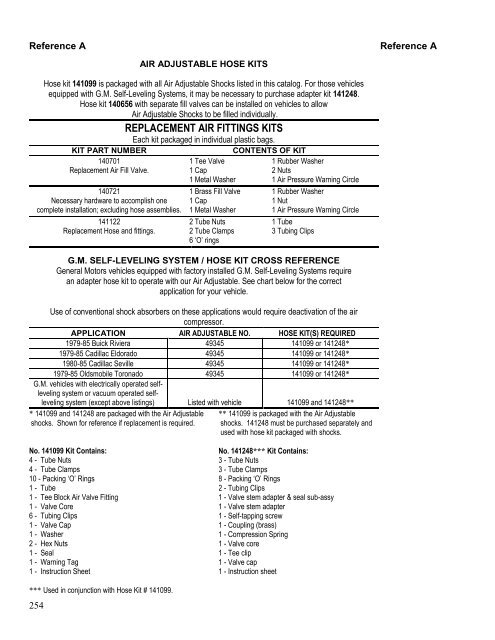
Reference AENSEMBLES DE BOYAUX POUR HI JACKERReference AUn ensemble de boyaux 141099 doit être commandé avec chaque paire de Hi Jacker listé dans cecatalogue. L‟ensemble d‟adaptateurs 141248 est également requis pour les véhicules GM équipé d‟un“Self Leveling System”.ENSEMBLES DE QUINCAILLERIE DE REMPLACEMENTPOUR SYST ME DE COMPRESSIONChaque ensemble est emballé individuellement dans <strong>des</strong> sachets plastiques.NUMÉRO DE PIÈCECONTENU DE L’ENSEMBLE140701Soupape de remplissage d‟air de remplacement.140721Quincaillerie nécessaire pour une installationcomplète, boyaux non inclus.141122Boyaux et raccords de remplacement.1 Valve en “T”1 Capuchon1 Rondelle de métal1 Écrou1 Capuchon1 Rondelle de métal1 Tuyau3 Bri<strong>des</strong> de tuyau6 Joints toriques1 Rondelle de métal2 Écrous1 Anneau indicateur de1 Valve de remplissage cuivre1 Rondelle de caoutchouc1 Anneau indicateur de2 Colliers de serrage pour tuyau2 Écrous pour tuyauLISTE DE RENVOIS POUR ENSEMBLES DE BOYAUX“SELF LEVELING SYSTEM” DE GMLes véhicules General Motors équipé d‟un “Self Leveling System” installé en usine requièrent un ensembled‟adaptateurs de boyaux pour fonctionner avec notre système Hi Jacker. Consultez le tableau ci-<strong>des</strong>souspour l‟application appropriée à votre véhicule.Pour utiliser <strong>des</strong> amortisseurs conventionnels avec ces applications, on doit désactiver le compresseur d‟air.APPLICATION AIR ADJUSTABLE NO. HOSE KIT(S) REQUIRED1979-85 Buick Riviera 49345 141099 or 141248*1979-85 Cadillac Eldorado 49345 141099 or 141248*1980-85 Cadillac Seville 49345 141099 or 141248*1979-85 Oldsmobile Toronado 49345 141099 or 141248*141099:4 - Écrous pour tuyau4 - Colliers de serrage pour tuyau10 – Joints toriques1 - Tuyau1 - Raccord de soupape en “T”1 - Noyau de valve6 - Bri<strong>des</strong> pour tuyau1 - Capuchon de soupape1 - Rondelle2 - Écrous à hexagonaux1 - Joint d‟étanchéité1 - Étiquette de prévention1 - Feuille d‟instructions* Utiliser conjointement avec l‟ensemble de boyaux no. 141099.141248*:3 – Écrous pour tuyau3 – Colliers de serrage pour tuyau8 – Joints toriques2 – Bri<strong>des</strong> de tuyau1 – Sous-assemblage d‟adaptateurs de corps devalve et de joint d‟étanchéité1 – Adaptateur de corps de valve1 – Vis à tôle autotaraudeuse1 – Raccord en cuivre1 – Ressort de compression1 – Obus de valve1 – Bride en “T”1 – Bouchon de valve1 – Feuille d‟instructions255
Reference AReference AEQUIPOS DE MANGUERA DE AIRE AJUSTABLEEl paquete de manguera 141099 viene con todos los Amortiguadores de Aire Ajustables en este catalogo. Paralos autos equipados con Sistema de Auto Nivelación G.M., puede ser necesario comprar el paquete conadaptador 141248. El paquete de manguera 140656 con válvulas separadas puede ser instalado en el autopara permitir que los amortiguadores de Aire Ajustable puedan ser cargados individualmente.PAQUETES PARA REEMPLAZAR EQUIPOS DE AIRECada paquete esta empacado en bolsas plásticas.NUMERO DE PARTECONTENIDO140701Válvula de aire para reemplazo.1 Válvula de arriba1 Tapa1 Arandela de metal1407211 Válvula de latónHerramienta necesaria para una instalación completa; 1 Tapaexcluyendo el ensamblaje de la manguera. 1 Arandela de metal141122Reemplazo de manguera y equipos.2 Tuercas de tubo2 Ganchos de tubo6 „O‟ anillos1 Arandela de caucho2 Tuercas1 Anillo de alerta de presión de aire1 Arandela de caucho1 Tuerca1 Anillo de alerta de presión de aire1 Tubo3 Agarraderas para tuboSYSTEMA G.M. AUTO NIVELACION / PAQUETE DE MANGUERAPARA REMISIONLos autos de General Motors con equipos de fábrica de Sistema de Auto-Nivelación G.M. requieren unadaptador de manguera para operar con nuestro Aire Ajustable. Vea la lista de abajo para la aplicación correctapara su auto.El uso del amortiguador convencional en esta instalación requerirá la <strong>des</strong>activación del compresor del aire.APLICACION AIR- AJUSTABLE NO. PAQUETE(S) DE MANGUERA EQUERIDO1979-85 Buick Riviera 49345 141099 o 141248*1979-85 Cadillac Eldorado 49345 141099 o 141248*1980-85 Cadillac Seville 49345 141099 o 141248*1979-85 Oldsmobile Toronado 49345 141099 o 141248*Los autos G.M. con sistema de autonivelaciónoperados electrónicamente o losoperados con sistema de auto nivelación alvacío (excepto los de la lista de arriba)Información viene en elmanual141099 y 141248*** 141099 y 141248 están empacados con amortiguadores de AireAjustable. En lista como referencia, si es necesario reemplazarlos.No. 141099 Empaque contiene:4 - Tuercas de tubo4 - Ganchos de tubo10 – Empaque de „O‟ anillos1 - Tubo1 - Equipo de válvula de aire de bloqueo dearriba1 - Válvula central6 - Agarraderas para tubo1 - Tapa de válvula1 - Arandela2 - Tuercas hexagonales1 - Sello1 - Tiquete de advertencia1 - Hoja de instrucciones*** Use junto con el paquete de manguera # 141099.** 141099 esta empacado con los amortiguadores de AireAjustable. 141248 deben comprarse separadamente y usarloscon el paquete de manguera empacados con amortiguadores.No. 141248*** Empaque contiene:3 – Tuercas de tubo3 – Ganchos de tubo8 - Empaque de „O‟ anillos2 – Agarraderas para tubo1 – Válvula con adaptador de tubo & sellado subalterno1 - Válvula con adaptador de tubo1 – Tornillo auto-golpes1 - Combinación (latón)1 – Resorte de compresión1 – Válvula central1 – Agarradera de arriba1 – Tapa de válvula1 – Hoja de instrucciones256
Reference AReference ASELF LEVELING SYSTEM ELECTRONIC COMPRESSORDEACTIVATION PROCEDURE FOR GM MODELSWhen installing conventional struts/shock absorbers on GM models equippedwith self leveling rear suspension that uses an electronic compressor the followingprocedure should be used:1. Locate height sensing unit on under body <strong>of</strong> vehicle approximately above theindependent suspension/rear axle. Locate a small link connected to theindependent suspension control arm/rear axle trailing arm. The upper end<strong>of</strong> this link will be connected to the electronic height sensing unit.2. Unplug electrical wire harness from the height sensing unit. System is nowdeactivated.3. Cover exposed electrical connector with tape or other suitable material andsecure to underside <strong>of</strong> vehicle.4. It is Not necessary to disconnect link to suspension control/axle trailing arm.257
Reference AReference ACOMPRESORES ELECTRONICOSCON SISTEMA DE AUTO NIVELACIONPROCEDIMIENTO PARA DESACTIVAR LOS MODELOS GMCuando instale struts convencionales/amortiguadores de absorción en los modelosGM equipados con auto nivelación en la suspensión trasera, que usa un compresorelectrónico se debe hacer lo siguiente:1. Ubique la unidad sensora debajo del la carrocería del auto que esta encima de lasuspensión independiente/eje trasero. Ubique una pequeña conexión pegada alcontrol/eje trasero del remolque. La parte superior de esta unidad estaráconectada a la unidad sensora electrónica.2. Desconecte los cables eléctricos del control de la unidad sensora. El sistema estáahora <strong>des</strong>activado.3. Cubra el conector que esta expuesto con cinta u otro material apropiado yasegúrelo por debajo del auto.4. No es necesario <strong>des</strong>conectar la conexión del control de la suspensión/eje traserodel remolque.259
Reference CReference CSTEERING STABILIZER BOOTSCOLORBOOTSPART NUMBERRED 142001BLACK 142005DARK BLUE 142008BOTTES DE STABILISATION DE CONDUITECOULEURBOTTESNUMÉRO DE PIÈCEROUGE 142001NOIR 142005BLEU FONÇÉ 142008ZAPATOS ESTABILIZADORES DE LA DIRECCIONCOLORZAPATOSNUMEROROJO 142001NEGRO 142005AZUL OSCURO 142008Page 265
Reference DReference DELECTRONIC ADJUSTABLE SUSPENSION CONVERSIONSome vehicles equipped with Electronically Adjustable Suspension can have a non-adjustable strut / shock replacement. Thefollowing is a list <strong>of</strong> those vehicles and the procedures for replacement.BUICK PARK AVENUE 1993-96 with CCR (Computer Command Ride) Remove the strut actuators Remove the CCR. It is located under the driver’s seat.o Reference GM Document VSS20000025 Remove struts and install G56718 Front and one <strong>of</strong> the following Rears:o G56707, G56726, G56903, G56906BUICK SKYLARK 1992-94 with CCR (Computer Command Ride) Remove the shock and strut actuators Remove the CCR. It is located behind the sound insulator panel, right side.o Reference GM Document VSS20000025 Remove the shocks and struts and install G56719, G56720 front and 69749 rear.CADILLAC DEVILLE 1991-93 with CCR (Computer Command Ride) Remove the strut actuatorso Reference GM Document VSS20000025 and GM Service Manual for system adjustment. Remove struts and install G56718 front and one <strong>of</strong> the following rears:o G56707, G56726, G56903, G56906CADILLAC ELDORADO 1991-92 with CCR (Computer Command Ride) or SSS (Speed Sensitive Suspension) Remove the strut actuatorso Reference GM Document VSS20000025 and GM Service Manual for system adjustment. Remove struts and install G56717 front and G56704 rear.CADILLAC SEVILLE 1991-92 with CCR (Computer Command Ride) or SSS (Speed Sensitive Suspension) Remove the strut actuatorso Reference GM Document VSS20000025 and GM Service Manual for system adjustment. Remove struts and install G56717 front and G56704 rear.CHEVROLET CORVETTE 1990-96 with ERC (Electronic Ride Control) Remove the shock actuators. Unplug the ERC module. It is located in the rear cargo area. Remove the shocks and install 69811 or 75811 front and 69795 or 75795 rear.FORD PROBE 1989-92 with PRC (Programmed Ride Control) Remove the strut actuators. Unplug the PRC module. It is located under the front passenger seat. Remove the struts and install G55600 front and G55601 rear.FORD THUNDERBIRD TURBO COUPE 1987-88 with PRC (Programmed Ride Control) Remove the strut and shock actuators. Unplug the PRC module. It is located in the rear cargo area. Remove the struts and shocks and install G56504 front and 69709 rear.MAZDA MX6 GT 1988-92 with AAS (Auto Adjust Suspension) Remove the strut actuators. Unplug the AAS module. It is located in the rear cargo area. Remove the struts and install G55600 front and G55601 rear.MAZDA RX7 TURBO 1989-90 and MAZDA RX7 GXL 1986-88 with AAS (Auto Adjust Suspension) Remove the strut and shock actuators. Unplug the AAS module. It is located in the rear cargo area. Remove the struts and install G55542 front and G51031 rear.Page 266
Reference DReference DELECTRONIC ADJUSTABLE SUSPENSION CONVERSIONMAZDA 626 1988-92 with AAS (Auto Adjust Suspension) Remove the strut actuators. Unplug the AAS module. It is located in the rear cargo area. Remove the struts and install G55600 front and G55601 rear.MAZDA 929 1988-89 with AAS (Auto Adjust Suspension) Remove the strut and shock actuators. Unplug the AAS module. It is located in the rear cargo area. Remove the struts and install G55713 front and G51192 rear.MAZDA 929 1990-91 with AAS (Auto Adjust Suspension) Remove the strut and shock actuators. Unplug the AAS module. It is located in the rear cargo area. Remove the struts and install G55716 front and G51192 rear.MERCURY COUGAR XR7 1987-88 with PRC (Programmed Ride Control) Remove the strut and shock actuators. Unplug the PRC module. It is located in the rear cargo area. Remove the struts and shocks and install G56504 front and 69709 rear.MITSUBISHI MONTERO 1992-96 with VSA (Variable Shock Absorbers) Remove the shock actuators. Unplug the module. It is located behind the left rear trim panel. Remove the shocks and install G63782 or 77782 front and G63781 or 77781 rear.NISSAN MAXIMA 1989-94 with NSS (Nissan Sonar Suspension) II Remove the strut actuators. Unplug the NSS module. It is located in the console. Remove the struts and install G55607, G55608 front and G44990 rear.NISSAN PATHFINDER 1987-95 with ASA (Adjustable Shock Absorber) Remove the shock actuators. Unplug the control switch. It is located in the console. Remove the shocks and install G63904 or 77904 front and G63492 or 77492 rear.OLDSMOBILE ACHIEVA 1992-94 with CCR (Computer Command Ride) Remove the shocks and strut actuators Remove the CCR. It is located behind the sound insulator panel, right side.o (Reference GM Document VSS20000025 Remove the shocks and struts and install G56719, G56720 front and 69749 rear.OLDSMOBILE NINETY EIGHT 1991-96 with CCR (Computer Command Ride) Remove the strut actuators. Remove the CCR. It is located under the driver’s seat. Remove struts and install G56718 front and one <strong>of</strong> the following rears:G56707, G56726, G56903, G56906PONTIAC BONNEVILLE 1994-99 with CCR (Computer Command Ride) Remove the strut actuators. Remove the CCR. It is located under the driver’s seat. Remove struts and install G56718 front and one <strong>of</strong> the following rears:G56707, G56726, G56903, G56906TOYOTA SUPRA from MARCH 1986-95 with TEMS (Toyota Electronic Modulated Systems) Remove the shock actuators. Unplug the TEMS module. It is located under the dash. Remove the shocks and install G51197 front and G51193 rear.Page 267
Reference HReference HDISPOSAL OF OLD OR DEFECTIVE GAS-PRESSURIZED SHOCKS & STRUTSUsed struts and shocks should be stored sothat any oil leakage will be properly collected.Those containers used to store this productshould be labeled “USED OIL”.STORAGE OF USED SHOCK ABSORBERS AND STRUTSRECYCLING OF SHOCK AND STRUT OILUsed struts and shocks can either bepunctured to recycle the shock oil or disposed<strong>of</strong> in a manner consistent with local or stateprograms.1. FOR YOUR SAFETY, ALWAYS WEAR SAFETY GLASSES AND PROTECTIVE GLOVESWHEN PUNCTURING STRUTS AND SHOCKS.2. Securely mount the strut or shock in a vice in the horizontal position. Make sure that the pistonrod is fully extended prior to drilling the unit (Fig. #1).3. Using a 1/16” or 1/8” drill bit, drill a hole in a downward direction approximately 1.0” from thebottom <strong>of</strong> the strut or shock (Fig #2). It is important to cover the area where the hole is beingdrilled with a towel or some type <strong>of</strong> shield to prevent spraying gas and oil upon initial penetration <strong>of</strong> thedrill bit.4. After the gas pressure is released continue drilling into the inner cylinder <strong>of</strong> the strut or shockunit, approximately ½” deep. Drill a second ½” hole near the top <strong>of</strong> the unit.5. Remove the strut or shock from the vice and hold it over a container to collect the used oil.Hand stroke the unit to completely purge the oil from the cylinder <strong>of</strong> the unit (Fig #3).6. Collect all used oil, being careful not to mix this oil with any other waste or refuse. Store inDOT approved containers labeled “USED OIL”.7. Dispose <strong>of</strong> the remaining strut or shock body and internal parts in accordance with local orstate regulations (e.g., scrap metal recycler).8. Store, dispose, and/or transport used oil in accordance with EPA regulations and your state’sused oil program.FIG. #1 FIG. #2 FIG. #3Page 265
Reference HReference HDISPOSITION DE VIEUX OU DÉFECTUEUX CHOCS ET DE CONTREFICHES DEGAS-PRESSURIZEDSTOCKAGE DES AMORTISSEURS ET DES CONTREFICHES UTILISÉSDes contrefiches utilisées et les chocs devraient être stockés <strong>des</strong>orte que n'importe quelle fuite d'huile soit correctementrassemblée.Ces récipients stockaient ce produit devraient être marqués "HUILEUSÉE".Des contrefiches utilisées et les chocs peuvent secrever pour réutiliser l'huile de choc ou en quelque sortele conformé débarassé aux programmes de gens dupays ou d'état.RÉUTILISATION DU CHOC ET DE L'HUILE DE CONTREFICHE1. POUR VOTRE SÛRETÉ, TOUJOURS VERRES DE SÛRETÉ D'USAGE ET GANTS PROTECTEURS ENCREVANT DES CONTREFICHES ET DES CHOCS.2. Montez solidement la contrefiche ou la choquez dans un vice en position horizontale. Assurez-vous que latige de piston est entièrement prolongée avant de forer l'unité (fig.# 1).3. Emploi d'un morceau de foret de 1/16"ou de 1/8", forez un trou dans un sens de haut en basapproximativement 1.0"du fond de la contrefiche ou le choquez (figue # 2). Il est important de couvrir ledomaine où le trou est foré avec un essuie-main ou un certain type d'écran protecteur pour empêcherpulvériser le gas et le pétrole sur la pénétration initiale du morceau de foret.4. Après que la pression de gaz soit libérée continuent de forer dans le cylindre intérieur de la contrefiche ouchoquez l'unité, approximativement ½ "pr<strong>of</strong>ondément. Trou forez deuxième ½ "près du <strong>des</strong>sus de l'unité.5. Enlevez la contrefiche ou la choquez du vice et tenez-l'au-<strong>des</strong>sus d'un récipient pour rassembler la huileusée. Course de main l'unité pour purger complet l'huile du cylindre de l'unité (figue # 3).6. Rassemblez toute la huile usée, faisant attention à ne pas mélanger cette huile à tout autre erteou à ne pas refuser. Le magasin dans le POINT a reconnu <strong>des</strong> récipients marqués "HUILE USÉE".7. Débarassez-vous de la contrefiche restante ou choquez le corps et les pièces internes selon les règlementsde gens du pays ou d'état (e.g., recycleur en métal de chute).8. Magasin, disposez, etou le transport a employé l'huile selon <strong>des</strong> règlements d'EPA et leprogramme de la huile usée de votre état.FIG. #1 FIG. #2 FIG. #3Page 266
Reference HReference HCOMO DESHACERSE DE AMORTGUADORES Y STRUTS VIEJOS ODEFECTUOSOS -SIN PRESURIZACION CON GASALMACENAJE DE AMORTIGUADORES Y STRUTS USADOSLos struts y amortiguadores deben almacenarse para que el aceite sepueda recoger. Los recipientes que se usen para almacenar esteproducto deben tener una etiqueta que diga: ACEITE USADO”.Los struts y amortiguadores pueden ser perforadospara reciclar el aceite o <strong>des</strong>hacerse de una maneraconstante con un programa local o del estado.RECYCLAJE DEL ACEITE DE AMORTIGUADOR Y STRUT1. PARA SU SEGURIDAD, SIEMPRE USE ANTEOJOS DE SEGURIDAD Y GUANTES CUANDOPERFORE LOS STRUTS Y LOS AMORTIGUADORES.2. Asegure la montura del strut o amortiguador sobre una manija horizontalmente. Asegúrese de que lavarilla del pistón este totalmente extendida antes de taladrar la unidad (Fig. #1).3. Use una broca de taladro de 1/16” o de 1/8”, taladre un hueco de para abajo, aproximadamente de 1.0”en la parte de abajo del strut o amortiguador (Fig. #2). Es importante cubrir el área en que taladre conuna toalla o cualquier otra manera de protección, para evitar que el gas y el aceite salten por todaspartes cuando haga la primera incisión con la broca.4. Después de que la presión del gas salga continúe taladrando dentro del cilindro interior del strut oamortiguador, aproximadamente ½” de pr<strong>of</strong>undidad. Taladre un Segundo hueco de ½” cerca de la partede arriba de la unidad.5. Remueva el strut o amortiguador del la manija y sosténgala sobre un recipiente para colectar el aceiteusado. Sacuda la unidad para sacarle completamente el aceite del cilindro de la unidad. (Fig. #3).6. Recoja el aceite usado, tenga cuidado de no mezclar este aceite con otro <strong>des</strong>perdicio o basura.Almacene en recipientes aprobados por el DOT con una etiqueta que diga: “ACEITE USADO.”7. Deshágase de los sobrados del strut o amortiguador y las partes interiores de acuerdo con lasregulaciones locales o del estado (por ejemplo: reciclaje para sobras de metal).8. Almacene, <strong>des</strong>hágase, y/o lleve el aceite usado de acuerdo con las regulaciones del EPA y el programade aceite usado.FIG. #1 FIG. #2 FIG. #3Page 267