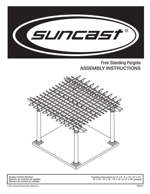
Free Standing Pergola ASSEMBLY INSTRUCTIONS - Easy2.com
Free Standing Pergola ASSEMBLY INSTRUCTIONS - Easy2.com
Free Standing Pergola ASSEMBLY INSTRUCTIONS - Easy2.com

You also want an ePaper? Increase the reach of your titles
YUMPU automatically turns print PDFs into web optimized ePapers that Google loves.
<strong>Pergola</strong> Safety and Care• Wash pergola with garden hose or mild detergent solution and soft cloth. Do not use a stiff brush or abrasivecleaner as that could damage pergola.• Hot items, such as recently used grills, blowtorches, etc., must not be used in or near the pergola.Tools Needed for Installation8'8'Assembly Day Tips• Complete site preparation and foundation construction before unpackingparts and beginning assembly.• Take care when removing vinyl parts. Other parts are packed inside them.• Do not attempt to assemble on a day with strong winds.• Do not attempt to assemble on days when temperature is below 32 degrees.• Set aside appropriate amount of time to completely assemble pergola.See the chart below for approximate assembly times.8x8 8x12 10x14 10x16 12x16 14x14 14x205 hours 6 hours 6 hours 7 hours 8 hours 8 hours 9 hours• Make sure you have assistance nearby to lift and secure parts in place.• Wear light duty work gloves while assembling pergola.• If you have questions on assembly, please call 1-800-444-3310.Note: This product contains parts that are used in different orientations to construct the pergola. Please take noteof the orientation of the parts shown throughout this instruction manual. Failure to follow instructions could result indamage to parts. Suncast is not responsible for replacing parts lost or damaged due to incorrect assembly.3
PartsIPost coverGTop trim ringHTop squarepost sleeveFRound trim ringA4x4 wood postDVinyl columnTemporaryBeam HolderBBTemporarybeam holderx2CCWood blockx2BCELarge basetrim ringDDWood pegx2Foot bracketOptional high-windbracket<strong>Pergola</strong>SizeA B C D E F G H I8x8 4 4 4 4 4 4 4 4 48x12 4 4 4 4 4 4 4 4 410x14 4 4 4 4 4 4 4 4 410x16 6 6 6 6 6 6 6 6 612x16 6 6 6 6 6 6 6 6 614x14 4 4 4 4 4 4 4 4 414x20 6 6 6 6 6 6 6 6 64
PartsSShade trimRShadeTShade spliceORafter collarNRafter sleeveQRafter trimP7' wood rafter insertL1' Wood beam insertK7' Wood beam insertJBeam sleeveMBeam trim<strong>Pergola</strong>SizeJ K L M N O P Q R S T8x8 4 0 8 8 6 0 0 12 8 16 08x12 8 4 8 8 9 0 0 18 16 16 810x14 8 4 8 8 18 9 9 18 20 20 1010x16 8 4 8 8 22 11 11 22 20 20 1012x16 8 4 8 8 22 11 11 22 24 24 1214x14 8 4 8 8 18 9 9 18 28 28 1414x20 12 8 8 8 26 13 13 26 42 28 285
HardwareW5/16" x 4" Structural stainlesssteel white pan head screwsX#8 1" ScrewsV3/16" Concretedrill bitU1/4" Wooddrill bitY2 1/2" Stainless steelwhite pan head screwsAA1/2" x 4" Concretescrews/boltsZConcrete screwsFFRafter clipEEWashersNote: These pieces shown at actual size.<strong>Pergola</strong>SizeU V W X Y Z AA EE FF8x8 1 1 18 128 72 17 8 16 258x12 1 1 18 204 96 17 8 16 3710x14 1 1 18 208 124 17 8 16 3710x16 1 1 26 244 152 25 12 16 4512x16 1 1 26 248 176 25 12 16 4514x14 1 1 18 216 164 17 8 16 3714x20 1 1 26 320 242 25 12 16 536
Site preparation, unpacking, and platform construction(Materials NOT supplied with <strong>Pergola</strong> Kit)Note: Site preparation and platform construction and Support Post Installation steps may require professionalassistance to be installed correctly.Please read all manual steps thoroughly before starting this project.Note: Site preparation and platform construction are required for this pergola. Placing the pergola on the groundwithout any type of foundation is not recommended. Suncast is not responsible for replacing parts damaged orproperty lost due to construction without a foundation or platform.Complete the site preparation and platform construction before unpacking parts.To prepare your pergola site, follow these steps:1) Consult your local authorities and neighborhood association for building codes and covenants beforebeginning foundation or erecting pergola.2) Consult your local building supply retailer to assist you in determining the best foundation or platformmethod for your application. The building supply retailer can also help you determine what anchoringhardware you will need once the foundation or platform method has been determined. Bring this manualwith you to the retailer so they can see the scope of the project.3) Before any digging, check with local utilities to determine location of buried cables, pipes, etc.4) A four inch thick concrete slab or concrete piers are recommended as the foundation.- If a wood platform is chosen as the foundation, use exterior grade wood.Note: Do not erect pergola on paver bricks. Foundation must be a solid surface.If you plan to erect the pergola on an existing deck, consult local authorities for building codes and make surethat the structure is sound and can hold the additional weight of the pergola (see chart below). Consult localbuilding supply retailer to determine the best method and hardware for your application.8x8 8x12 10x14 10x16 12x16 14x14 14x20335 lbs 405 lbs 565 lbs 745 lbs 865 lbs 683 lbs 985 lbs5) Preparing the building site:- The ground should slope away from the foundation area to provide drainage.- The foundation surface must be flat and level.- Follow local building codes for a proper vapor barrier.For installation on concrete pillars:Using the chart provided on Page 8, mark the location of the center of each post. Prepare a hole that is 16inches in diameter, adjusting the depth as needed for the area of the country that you are in. For example,because of frost issues, the northern part of the US requires a deeper hole than the southern part. Make surethat the finished height of the concrete is exactly the same for all of the post foundations.7
Specs for post and beam layoutProper site preparation requires that the layout is square. Use the measurements on the chart provided todetermine the correct spacing of the posts (A & B). The diagonal measurement (C) will ensure that the pergolais square.Four post layoutSix post layoutB(beams)B(beams)B(beams)A (rafters)CA (rafters)CSpecs and DimensionsTop size infeetRafter lengthincluding endsin inchesBeam lengthincluding endsin inches# of posts # of doublebeamsDepth (A)in inchesWidth (B)in inchesDiagonal (C)in inches8x8 106 114 4 2 74 74 104.658x12 106 158 4 2 74 118 139.2810x14 130 182 4 2 96 142 171.4110x16 130 204 6 2 96 82 190.0312x16 154 204 6 2 120 82 203.2114x14 178 182 4 2 144 142 202.2414x20 178 261 6 2 144 110.50 263.77Note: The measurements on the chart are from center to center of the posts.Post BPost C2x8 Beams2x6 Rafters @ +or- 16" apartPost B & DorientationElevation BShades @ +or- 12" apartPost A & Corientation4x4 Post wrappedw/ vinyl columnPost AElevation A8Post D
ElevationsShade trimHollow shadesShade splice2x6 Rafters w/ wood fillersRafters secured tobeams w/ rafter clipsBeam trim2x8 Beams w/ wood fillers8' 9"4x4 PostVinyl columnFoundation by othersELEVATION A1' wood fillerinside beamsBeams (& 1' filler) secured topost w/ 4" structural screwsRafter trimHollow shadesShades secured w/2.5" screws2x6 Rafters w/ wood fillers8' 9"7' 6"Rafter clips securedw/ 1" screwsFoundation by othersELEVATION B9
Optional High-Wind Bracket Pre-assembly1 Bx102ACAIf you have chosen to purchase the high-windbrackets (C), remove the screws in the existingbrackets (B). Set brackets aside and save all screwsfor later.Slide the high-wind bracket (C) onto the bottom ofthe post (A), making sure that it is snug against thebottom.3CAAttach the high-wind bracket (C) using the screwsthat were removed in Step 1. The high-wind bracketuses an additional 14 screws that are included.The post with the high-wind bracket should look aspictured.10
Support Post Installation351XX' X"XX' X"Using the chart on page 8, determine post layout.Mark each post location. Each mark will be theexact center of the posts.2aStandard bracket2bOptional high-wind bracketAABC1122Position post (A) and foot bracket (B) over mark andtrace holes in bracket.For high wind areas, position post (A) and high-windbracket (C) over mark and trace holes in bracket.11
3aStandard (3/16" drill bracket bit)(3/16" drill bit)V3bOptionalhigh-wind bracket(1/2" drill bit)(not included)Drill holes using the 3/16" concrete drill bit (V)provided.For high-wind areas, use a 1/2" concrete drillbit (not included) to drill holes a minimum of 5" deep.451A1A2EEPosition wood posts (A) so that they are parallelwith each other. Using a string, align the tops ofthe posts. This will ensure that when the beams areattached, they will fit properly against the posts.Note: The bottom of the posts may not be perfectlyparallel. This is common and will not be visible oncethe vinyl columns are in place.12Position wood post over holes and plumb using afour foot level. If needed, use supplied washers toplumb posts. Note: The vinyl column covers bracket,this is your last opportunity to secure and plumb theposts.
6a6b Optional bolts AAZx4x2Use four concrete screws (Z) to secure. Tightensecurely. DO NOT proceed with post covers untilall wood posts are plumb and mounted securely.As an option, additional 1/2" x 4" concrete screws/bolts (AA) can be installed.6cOptional high-wind bracket7AA Repeat Steps 2-6for remaining posts.x4Use concrete screws/bolts (AA) to secure brackets.Tighten securely. DO NOT proceed with post coversuntil all wood posts are plumb and mounted securely.13
Post Trim Installation89HDEFGSlide vinyl column (D) over wood post. Fit lowerportion of vinyl column over wood spacers, untilcover rests securely on concrete surface.Unpack post trim boxes and position trim close toeach post in the order shown.1011FESlide the large base trim ring (E) over the top of thecolumn until it rests on the concrete surface.Slide round trim ring (F) down column until it restson the raised ledge.14
12G13HSlide top trim ring (G) over column, making sure therounded part is facing down and the square part isfacing up.Slide top square post sleeve (H) over wood post.14Repeat Steps 10-13for remaining posts.This is how the top post trim should look.15
15BB16CC1DD2 2Hook temporary beam holder (BB) on top of thesquare post sleeve, facing direction of post, whichwill be supporting the opposite end of the beam.Repeat for opposite post.Insert wood block (CC), making sure the two holesin the wood block are facing upward. Insert a woodpeg (DD) in each hole. Repeat for opposite post.This is how the temporary beam holder should lookwhen it is positioned to hold the beam during beaminstallation.16
Beam Assembly1721JKUnwrap beam sleeve (J) with the Suncast logo.Unscrew logo and remove. Set logo plate and goldscrews aside to be reattached later.Keep logo plate with screws.1819K16"2Slide 7' wood beam insert (K) out until 6" of the fillerpiece is exposed.Re-attach one side of the logo plate.17
2829JPosition two 8' step ladders next to two posts.Double check the orientation of the temporary beamholders and make sure they are positioned tosupport the beams. Ensure the Suncast logo isfacing outward and place the beam (J) onto thetemporary beam holders.30Center the beam on the two posts, making sure thatan equal amount of beam protrudes past each post.31UWUsing the pre-drilled holes that you drilled in Step26, drill a 1/4" pilot hole into the post. The pilot holeshould go through the post vinyl sleeve and into thewood 1/4".20Make sure that the beam is resting on top of thevinyl column and pressed securely against the4" square posts. Secure with two 4" pan headscrews (W) through the beam and into the post.Repeat on opposite end of beam.
32JThe installed beam should look like this.Position next assembled beam (J) on opposite sideof post. Make sure the pre-drilled holes are facingoutward and towards the bottom.33 341Repeat steps 28-31to install oppositebeam.DD1BB2CC3Remove wood pegs (DD) and slide out wood blocks(CC) to remove temporary beam holders (BB).Reinstall them, as needed, on remaining posts.21
39FF4011X X XXX2XAttach a rafter clip (FF) directly over the top of thebeam splice in the center of each beam with two1" screws (X).Refer to the chart to determine rafter clip spacing.Using a tape measure and pencil, mark the location ofrafter clips.<strong>Pergola</strong> SizeRafter Spacing(on center)Number ofRafters8x8 16 3/4" 641FF8x12 16" 910x14 19" 910x16 17 3/8" 1112x16 17 3/8" 111114x14 19" 914x20 19 1/4" 132XInstall remaining rafter clips (FF) using two1" screws (X) on each clip.23
Rafter Assembly4243NRepeat steps 37-41to install remainingbeams and rafter clips.P42"Slide the 7' wood rafter insert (P) out of the raftersleeve (N) until it protrudes 42".441 1/2"45NXNPOInsert a 1" screw (X) 1 1/2" from the end of the raftersleeve (N).Slide rafter collar (O) onto 7' wood rafter insert (P)so that half of it rests on the rafter sleeve (N).24
46471P1NRepeat steps 43-46to assemble remainingrafters.2XSlide rafter sleeve (N) over 7' wood rafter insert (P)until the two vinyl sleeves are touching. Insert a1" screw (X) next to the collar.48Installing the Rafters49NAt this point in the assembly process, all of theposts, beams, and rafter clips should bepermanently installed. All of the rafters should beassembled and ready to be installed.25Position two step ladders next to two posts.Place each end of a rafter (N) into the outer mostrafter clips on the beams.
5455Repeat steps 49-52to center rafter andsecure rafter torafter clips.4"Before moving on, measure the beams at the seamto make sure the spacing between the beams is 4". Ifneeded, temporarily insert a 4" spacer while attachingremaining rafters.56Position the remaining rafters, fitting them inside therafter clips. DO NOT attach any, until all have beencentered and positioned. Adjust the rafters asneeded, make sure all rafters line up perfectlystraight before securing to rafter clips.27After rafters have been installed the pergola shouldlook like this.
Assembling the Shades5758RRT11TR2X2XSlide the shade splice (T) halfway into shade (R).Insert a 1" screw (X) about 1" from end of the shade.Installing the Shades59Slide another shade (R) over shade splice (T), untilit butts against exisiting shade. Insert a 1" screw (X)about 1" from end of the shade.60 RR1 1/2"1 1/2"Measure 1 1/2" from each end of the outermostrafters to establish the location of the two outsideshades.Lay the two outside shades (R) on top of rafters.Make sure that the splice (where the two shadescome together) is directly centered over the middlerafter.28
XX6112 1/8"12 1/8" 12 1/8" 12 1/8"Measure and mark rafters 12 1/8" from the center ofthe first shade for remaining shades.Prior to fastening the shades, sight the rafters andstraighten shades as needed.6263Secure remainingshades to rafters.YAfter positioning the shades, begin at the cornerand fasten shades using 2 1/2" pan head screws (Y).Ensure screws go through the top of the shade andinto the rafter.29
Installing Decorative Trim64MMMulti-purpose cement is provided to installdecorative trim.Apply cement to inside ring of beam trim (M).Promptly tap beam trim into place, so that trim issnug and level. Repeat for remaining beams.65Q66SQSApply cement to inside ring of rafter trim (Q).Promptly tap rafter trim into place, so that trim issnug and level. Repeat for remaining rafters.Apply cement to inside ring of shade trim (S).Promptly tap shade trim into place, so that trim issnug and level. Repeat for remaining shades.30
67Xx2EAfter beam, rafter, and shade trim have beeninstalled, the pergola should look like this.Make sure that the large base trim ring (E) is squareand parallel to the beam. Secure trim with two 1"screws (X) on opposite sides of the posts. Repeatfor remaining posts.Congratulations! Your pergola is now ready to enjoy.31
WarrantySuncast® Corporation, 701 North Kirk Road, Batavia, Illinois 60510 (Manufacturer) warrants to the originalpurchaser only that the enclosed product is free from material and workmanship defects under normal, householduse at time of purchase. Defective product or part must be returned, freight prepaid, to the Manufacturer'saddress (Attention: Parts Department) along with proof of purchase. Upon receipt of the aforesaid, the defectiveproduct or part will be repaired or replaced at the option of the Manufacturer without charge to the originalpurchaser and returned to the customer freight collect.This limited warranty does not apply to damage resulting from accident, neglect, misuse, commercial use, alteration,operation not in accordance with instruction or repairs made or attempted by unauthorized persons.This limited warranty applies only to the product enclosed and does not apply to accessory parts.THE MANUFACTURER'S LIABILITY HEREUNDER IS LIMITED SOLELY TO THE REPAIR OR REPLACEMENT OFTHE DEFECTIVE PRODUCT OR PART AND THE MANUFACTURER SHALL IN NO EVENT BE LIABLE FOR ANYINCIDENTAL OR CONSEQUENTIAL DAMAGES WHICH MAY RESULT FROM ANY DEFECT IN MATERIAL ORWORKMANSHIP OR FROM THE BREACH OF ANY EXPRESS OR IMPLIED WARRANTY.Some states do not allow the exclusion or limitation of incidental or consequential damages, or a limitation ofhow long an implied warranty lasts, so the above limitations may not apply to you. This warranty gives you specificlegal rights, and you may have other rights which may vary from state to state.Factory RepairsRepair service and assembly assistance are available direct from the factory, not from the place of purchase. Ifthis product requires repair, please call or write us. Warranty repair parts are sent out free of charge. If the productis out of warranty, we will inform you of the charges prior to sending out the parts. VISA and MasterCardare accepted on phone orders. To purchase Suncast replacement parts and learn more about other Suncastproducts, visit us online at www.suncast.com 24 hours a day, 7 days a week, 365 days a year, or call1-800-844-3310 Mon-Fri 6am-8pm CST.