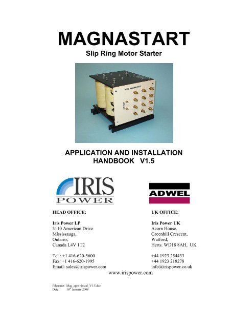
Download Magnastart handbook - PDF - Iris Power Engineering
Download Magnastart handbook - PDF - Iris Power Engineering
Download Magnastart handbook - PDF - Iris Power Engineering

You also want an ePaper? Increase the reach of your titles
YUMPU automatically turns print PDFs into web optimized ePapers that Google loves.
US Group• Fermilab (FNAL)• M. Demarteau, A. Ronzhin, K. Sogut, L. Spiegel, S. Tkaczyk+ technicians• Kansas State University (KSU) – will now mainly work on Pixels• T.Bolton, W.Kahl, R.Sidwell, N.Stanton• University of California, Riverside (UCR)• Gail Hanson, Gabriella Pasztor, Patrick Gartung• University of California, Santa Barbara (UCSB)• A. Affolder, S. Burke, C.Campagnari, D. Hale, J.Incandela, S. Kyre,J. Lamb, R. Taylor, D. White + techs.• University of Illinois, Chicago (UIC)• E. Shabalina, C. Gerber, T. Ten• University of Kansas (KU)• P. Baringer, A. Bean, D. Coppage, L. Christofek• University of Rochester (UR)• R.Demina, R. Eusebi, E. Halkiadakis, A. Hocker, S.Korjenevski,P. Tipton• Mexico:3 institutes led by Cinvestav Cuidad de Mexico• Brown is also planning to joinUCSB CMS Module Production Report - April 2004 – CERN Tracker week 2
using <strong>Magnastart</strong> is dissipated in the heavy mass of the steel cores, which can absorb aconsiderable amount of energy. Advanced thermal insulation protects the coils whichremain relatively cool, and several consecutive starts may be obtained on drives with highinertial loads.Each of the coils has four connection taps brought out to studs on the front panel. By usingvarious star and delta combinations, up to 17 different starting impedances are available, toprovide the best starting characteristics on a wide range of motors.4. CONSTRUCTIONThe <strong>Magnastart</strong> chassis consists of two rectangular steel plates. Between these aresandwiched the three specially shaped, hollow steel cores, in a triangular array. The coresare specially shaped to give the special electrical characteristics required. On each core iswound a coil. On the smallest model, this is wound directly onto the core. On all othermodels the coil is supported at top and bottom by six heat-resistant supports. There is a5mm air gap between the coil and the core to thermally insulate the coil from the core,where most of the heat is dissipated.Each coil is tapped at 84% and 56%, and all the connections are brought out to the frontpanel in a rectangular array.<strong>Magnastart</strong> is built to have a large mass. The large weight of steel not only gives improvedelectrical performance, but also a high thermal capacity. Consequently, it is capable ofabsorbing the energy from a number of starts in succession.Page 6 V1.3
5. ELECTRICAL CHARACTERISTICSEach coil has two intermediate taps, one at 56% and one at 84%. The <strong>Magnastart</strong> issupplied with a set of links, which can be used to make up to 17 different connections onthe front panel. Each tapping has a different impedance at 50Hz. Motors with differentrotor parameters can be accommodated by the same <strong>Magnastart</strong> model, and by usingdifferent tappings on the same motor, different starting characteristics can be obtained. Alower impedance tapping will generally give a high torque and draw a large starting currentto produce a shorter start time, although at very low impedances, torque can decrease again.A higher impedance tap can be used to limit the starting current at the expense of startingtorque and a longer start time.A linear characteristic of impedance change with frequency is desired to give a constantcurrent and torque during starting, and this is substantially achieved by <strong>Magnastart</strong>Inducers. The result for the model M175 is given in Fig. 3 below.Braking4StartingImpedance Ω321Fig 30-10 0 10 20 30 40 50 60 70 80 90 100Speed %From this it can be seen that operation at 60Hz is little different, as the characteristicimpedance is increased by only about 12%.The power factor remains constant over the whole range at about 0.8. It should be notedthat all times the impedance is greatly in excess of the D.C. resistance of the coils.Consequently during normal operation, the heating in the copper is small in relation toheating in the iron, keeping the coils relatively cool even if the <strong>Magnastart</strong> is subjected to aheavy duty cycle.Page 7 V1.3
6. PERFORMANCEThe <strong>Magnastart</strong>’s linear impedance characteristic means that the stator current drawn onstart remains almost constant during three-quarters of the starting cycle. This hasconsiderable advantages when supply restrictions are in force, as it enables the fastestpossible start to be obtained within a given current limit.Typical torque and current to speed characteristics are given in the charts below to illustratethe benefits of using a <strong>Magnastart</strong> Inducer as a rotor starter, compared to direct on linestarting. (The impedance values 1-6 are nominal, and only reflect the typical range ofimpedances achievable from a <strong>Magnastart</strong>, not any particular tapping). Fig. 4 shows thevariation in starting torque as a proportion of Full Load Torque (FLT) with impedance.47Direct on Line6Direct on Line3Lowest Impedance 1Impedance 25Lowest Impedance 1Impedance 2Torque / FLT2Impedance 3Impedance 4Current / FLC43Impedance 3Impedance 41Impedance 5Highest Impedance 621Impedance 5Highest Impedance 600 10 20 30 40 50 60 70 80 90 10000 10 20 30 40 50 60 70 80 90 100Speed %Fig. 4 Fig. 5As can be seen, direct on line starting will give the least starting torque, and there is anoptimum impedance for maximising starting and run-up torque, with higher impedancesgenerally depressing both values (though reducing starting current). On most motors thismaximum starting torque occurs between 3 and 4 times the full load rotor current.<strong>Magnastart</strong> is most efficient, starting fan loads and large flywheels, at 2 times full loadrotor current.Fig. 5 shows the effect of the various impedances on starting line current, as a proportion ofnormal full load current (FLC), and illustrates that the starting current can be maintained atlow levels if high starting torque is not a key requirement. (As is normal, current andtorque both reduce to zero at 100% synchronous speed, ie no slip).Speed %Section 9 gives details of tappings and relative impedances achieved.Page 8 V1.3
7. RATING AND SELECTION OF MODELThe size of a <strong>Magnastart</strong> required is decided solely by the motor size and starting dutyrequired. Factors to be used in determining ‘starting duty’ are:• The number of starts per hour.• The starting period.• The starting current as a factor of full load rotor current.The rating of the required <strong>Magnastart</strong> is determined by the motor’s full electrical powerrating in kW/HP. It is not normally determined by the running mechanical load, sinceduring start-up the motor will draw the maximum power possible (usually well in excess ofthe normal running power) to accelerate the machinery’s mass.The ratings have been calculated on a basis of 15 second starts, with near-full-speed beingreached in ~10 seconds and being shorted in 15 seconds, generating a maximum of 1.5times the full load torque at start. For other starting conditions, the units can be up-rated orde-rated in proportion.In addition the motor’s rotor voltage and current ratings should be considered to make surethese do not exceed the <strong>Magnastart</strong>’s rating. Only very rarely do motors exceed the<strong>Magnastart</strong> ratings for rotor voltage or current. However, if the maximum rotor startingcurrent or voltage is exceeded, a larger <strong>Magnastart</strong> is needed. Note that the <strong>Magnastart</strong>rotor ratings allow a wide range of voltage and current capacity, but these must not be usedin conjunction beyond the maximum power rating of the <strong>Magnastart</strong>.The chart in Section 9 provides a selection of front panel tappings and their relativeimpedances. This is used to select the right tapping. If the impedance needed is not known(which is quite often), the right tapping can be found by attempting a start with a highimpedance tapping, then progressively trying lower impedance tappings until the rightstarting characteristics (line current vs time) are obtained. During the setting up operation,the rotor current should also be measured on each attempted start. This ensures that the<strong>Magnastart</strong> and motor rating is not exceeded and gives a guide to the additional torque thatmight be obtained on lower impedance tappings.8. INSTALLATION8.1. Enclosure and MountingThe <strong>Magnastart</strong> should be installed in a suitable metallic enclosure, protected fromhuman access. This need not be ventilated but reasonable space should be left eitherside of the <strong>Magnastart</strong> to allow circulation of air around the coils. The heat energydissipated in the <strong>Magnastart</strong> during a start is approximately the same as the storedkinetic energy in the motor and load.If it is mounted in the base of a control cubicle, ensure that enough ventilation ornatural cooling through the body of the cubicle is provided to prevent the heatgenerated during starting cycle(s) adversely affecting other equipment (eg PLC). ExtraPage 9 V1.3
or forced ventilation may be required in case of either a particularly compact housingor very arduous duty.During operation the top and bottom plates (and cores) of the <strong>Magnastart</strong> may becomevery hot as a natural part of the starting process. Make sure that heat sensitivecomponents, especially connection cables etc are not sited or routed close to theseareas.On the M30B, M45, M90, M125 and M175 the mounting channels can be removed andthe <strong>Magnastart</strong> mounted on the M8 studs protruding from the bottom of the rubbermounts. This allows these <strong>Magnastart</strong>s to be mounted in a 400mm deep enclosure.The mechanical dimensions and weight are given in the Specification in Section 11.8.2. ConnectionsThe connections should be all made to the front panel in flexible cables since there isconsiderable vibration during starting.Ensure the cables are rated for the specified motor current. If the <strong>Magnastart</strong> and itsshorting contactor is distant from the motor, consider over-sizing the rotor cables tominimize running losses in the cables.The <strong>Magnastart</strong> need not be earthed for safety, as no part of its construction or circuitryshould be exposed to risk of human contact. However some installers may wish tomake an earth connection for overall earth integrity, in which case one of the boltsholding the connection panel may be used, ensuring the paint underneath is cleaned offfirst.8.3. Voltage, Current and Frequency ratingsThe motor’s rotor voltage and current ratings should not exceed the <strong>Magnastart</strong>’srating. The stator voltage is normally not relevant to the installation unless any statorhigh voltage circuitry is installed in the vicinity when correct insulation co-ordinationis required.Operation is possible at 50Hz or 60Hz, and has the effect that the <strong>Magnastart</strong>impedance at 60Hz is increased by 10-15% over its nominal 50Hz rating. This is lessthan the difference between each impedance tap, and is thus usually not noticeable (ina few circumstances it may lead to the user choosing a slightly lower tap than theidentical system at 50Hz).Page 10 V1.3
8.4. Control and <strong>Power</strong> CircuitryThe Rotor and Control circuitry should be wired to the general principles describedbelow. Fig 6 shows a typical system wiring diagram for a basic starter. It should bestressed that this is intended as a base for the designer to use and adapt for his/her ownpurposes. It does not include any operating safety interlocks or extra controls forinching, supply protection arrangements, earthing, etc. It is common to use aProgrammable Logic Controller (PLC) to perform the overall control and interlockingfunction.The actual connections to the <strong>Magnastart</strong> are dependent on the Impedance settingrequired, covered in Section 9 below.Fig. 6 Basic Starter Wiring DiagramPage 11 V1.3
8.5. Setting the TimerIt is vital the <strong>Magnastart</strong> and rotor is shorted after starting to take the <strong>Magnastart</strong> out ofcircuit. The <strong>Magnastart</strong> coils are not rated to withstand the rotor current indefinitely,and should not exceed a start time before shorting of 15 seconds at their maximumrated current. As the heating effect is proportional to I 2 , then for example at 50% oftheir rated current, a maximum start time of 1 minute would be permitted.The timer should be set to close the rotor contactor after the motor has accelerated to asteady speed. If the current surge on closing is too large, then a lower impedancetapping may be required to get the motor nearer to full speed before closing. Thespeed can be checked with a tachometer if it is not easy to discern the speed or highaccuracy is required. If the motor has to start under varying load conditions, anadditional allowance should be made on the starting time to allow for a ‘worst case’start. Setting the timer a little too long will not affect the starter’s performance orreduce its starting capacity, as the <strong>Magnastart</strong> core dissipation is low once the motorreaches near full speed.Other controls (eg current or tachometer) may be used to determine the correct time toshort the rotor contactor. However since a varying load or operating defect could delaythe shorting time indefinitely, a time-out should still be used to either force a rotorshort or trip the drive, to protect the <strong>Magnastart</strong> from being in circuit indefinitely andthus overloaded. Please note that the cut-outs DO NOT detect overheating in the coils,thus a fault which causes continuous high currents in the <strong>Magnastart</strong> coils duringrunning will lead to premature failure.8.6. Inching and Speed ControlThe <strong>Magnastart</strong> Inducer is suitable for inching and the same impedance may used asfor normal starting. An interlock should be included to extend the rotor contactorclosing time during inching operations. No matter at what speed the inch button ispressed or released, the <strong>Magnastart</strong> will always provide the correct torque for efficientoperation automatically. If the inching operations are expected to be intensive, theneither extra ventilation and/or a larger model should be chosen, as this is equivalent toextended starting duty.The <strong>Magnastart</strong> Inducer is NOT suitable for speed control. The automatic reduction ofimpedance as the motor accelerates prevents a stable speed being achieved for a givenload, and the <strong>Magnastart</strong> rating is only for the intermittent duty of starting, notcontinuous running.8.7. ReversingBy fitting a reversing contactor into the stator circuit, the <strong>Magnastart</strong> can be used forreversing. The same <strong>Magnastart</strong> tapping would normally be used as for normalstarting. Again the rotor contactor must be interlocked to extend rotor shorting closuretime. The reversing torque will be at least the torque on start. If exceptionally heavybraking is required a lower impedance tapping may be required (though be aware thatvery low impedances can result in reduced torque).The use of the <strong>Magnastart</strong> to reverse a running motor will cause at least a double dutycycle (run-down and back up again), and this will impact the number of duty cycles. Inaddition, the maximum rotor voltage must be evaluated since at point of reverse thePage 12 V1.3
9. CHOOSING THE IMPEDANCE TAPPINGA wide number of tapping arrangements are possible. The connection diagrams for thepreferred values are given on the Preferred Impedance Tapping Chart in Fig. 7 below. Thearrowhead connections are made to the rotor. The cross-connections can be made up withthe set of cable links provided with each <strong>Magnastart</strong>.If there is no other information available, such as calculations made from motor and loaddata or similar previous installations, the tapping required may be determined by trial,using Tapping 1 for the initial test. Set the timer to maximum and attempt to start. SinceTapping 1 produces minimum torque and current, the motor may not move or may fail toreach full speed. Measure the starting line current and refer to the impedance values on theimpedance matching chart. For off-load starts 1x Full Load line Current should besufficient. Starts against load may require 2x or 3x FLC.In general to increase the starting current and torque, choose a lower impedance tapping.To reduce them, choose a higher impedance tapping. The % impedance values will give anapproximate indication of the change in starting current with different tappings though willnever exceed the direct-on-line starting current (eg if impedance is reduced from 100% to41%, starting current will increase by approximately 120%). Note that the energy that the<strong>Magnastart</strong> can absorb does not significantly vary with the tappings (unlike resistancestarters), as the great majority of the starting energy is absorbed in the iron cores. Eachstarting trial will heat the <strong>Magnastart</strong> up, so do not test too many times in successionwithout allowing adequate cooling periods, else the cut-out may tripA further seven Alternate Impedance Tapings are given in Fig. 7a below. These provide afine-tuning ability if the required impedance is found to lie between two preferred tappings,or a very low impedance is required. It is rarely required to use these, and the lowerimpedances will also need to have the cable and rotor impedance taken into account.In case that the motor is supplied from a generator or supply with limited overloadcapacity, the tapping will need to be chosen so that the supply voltage does not dropexcessively due to the stator starting current. This is needed to ensure that no damage isdone to the generator and the control systems operate correctly during starting. It may limitthe motor starting capacity against load.CHECK THE ROTOR CURRENT.DO NOT EXCEED THE SPECIFIED MAXIMUM ROTOR CURRENT.If the tapping chosen uses only some of each coil, it will act like an auto-transformer, andsignificant voltages will occur on unused terminals during starting. For most tappings thiswill not be a problem, but in the case of tapping 17 the voltages between the “0” terminalswill be 525% of rotor voltage, thus limiting the rotor voltage this can be used with. Thedesigner should consider this in the system insulation co-ordination, and may need todisallow certain tappings.Page 14 V1.3
Tapping 1 2 3 4 5Coil Taps100%84%56%0Impedance 100% 71% 67% 54% 41%.Tapping 6 7 8 9 10Coil Taps100%84%56%0Impedance 31% 26% 20% 15% 11%Fig. 7 Preferred Impedance TappingsTapping 11 12 13 14 15 16 17Coil Taps100%84%56%0Impedance 91% 57% 37% 12% 7.8% 6.9% 2.6%Fig. 7a Alternate Impedance TappingsPage 15 V1.3
10. CONNECTING MAGNASTARTS IN PARALLELThe maximum <strong>Magnastart</strong> rating is 370kW, but it may be desired to start a higher ratedmotor. In this case it is sometimes possible to connect 2 or more M350 <strong>Magnastart</strong>s inparallel to achieve a larger combined rating. This should only be considered for ratingsabove 370kW, it is normally more reliable (and more economic) to use a single, correctlysized <strong>Magnastart</strong> for lower ratings.In case <strong>Magnastart</strong>s are connected in parallel the following criteria MUST be applied.i) The <strong>Magnastart</strong>s are all tapped identically, andii) The Cut-outs on all units are wired in series, so that if any unit overheats, thesystem trips.iii) The system is de-rated by 10% to allow for mismatch of individual units.iv) The rotor voltage must not exceed the <strong>Magnastart</strong> rating.It will be obvious that operating in parallel will reduce the combined maximum impedance,so this arrangement functions best with lower voltage rotors. If this is problematic, then aseries/parallel combination could be considered, and must be designed specifically for theapplication by a competent Electrical Engineer.Since the success of this use is very dependant on the motor and system design, IRISPOWERdoes not guarantee that parallel operation will be successful in all cases, and theuser must satisfy themselves that the application is appropriate.Page 16 V1.3
11. SPECIFICATIONSModel No M30B M45 M90 M125 M175 M350Max Motor Size 1 kW 37 55 110 150 200 370HP 55 75 150 200 270 500Max Starts/Hr 2 9 7 6 7 5 4Max Consecutive Starts 3 4 4 4 5 4 4Max Rotor Starting Current Amps 140 275 425 525 625 1100Max Rotor Voltage 4 Volts 600 600 800 800 1000 1200Max Rotor Voltage (HD) 5 Volts 500 500 550 600 750 900Impedance 6 Ohms 7.0 4.0 3.5 2.5 3.0 2.3Coil Insulation RatingClass F (150°C), 4,000Vac winding-ground proof testThermal Overload Cut-out 7 250Vac, 10A or 30Vdc, 5A max Normally closedDimensions 8 mm See Mechanical Outline drawingHeight A 250 260 255 360 360 430Width B 305 325 365 365 365 500Depth C 320 330 420 425 420 500Body Width D 250 270 320 320 320 420Fixings Holes Side toSideE 280 300 340 340 340 470Fixings Front to Back F 233 257 320 320 320 360Rear Fixings G 25 25 30 30 30 70Fixing Hole Size H 10 10 10 10 10 12Fixing Studs Side to Side I 215 247 285 285 285 370Channel Height J 37 37 37 37 37 37Front Panel Inset K - - - - - 95Load Studs L M8 M8 M10 M10 M12 M12Overload Cut-out Studs L M6 M6 M6 M6 M6 M6Weight 9 kg 27 36 54 75 81 165Operating Environment-25°C to +50°C ambient, 0-95% RH (non-condensing)Notes:1. With 50/60Hz, 3 phase supply. For other supply arrangements contact ADWEL.It may be possible to parallel models for greater capacity in particular circumstances. Please consult IRIS POWERwithspecific details.2. This is based on the maximum motor size starting against 1.5 x full load torque for 15 secs, mounted in a typicalunventilated metallic enclosure. For heavier duties extra or forced ventilation may be required, or a larger <strong>Magnastart</strong>chosen.3. Maximum consecutive starts are from cold. Note that the motor rating may also limit consecutive starts.4. Normal starting duties, occasional inching in both directions.5. Heavy inching, and plug braking.6. Impedance is approximate per coil at 50Hz, full load, 100% tapping. Increase 12% for 60Hz. Typical PF is 0.8.Tappings at 84% and 56% per coil allow a choice of star and delta impedances from 100% down to 3% in 17 steps.7. The Thermal Overload Cut-out should be wired to trip the starting system in case of overload (contacts open).8. On the M30, M45, M90, M125 and M175 the mounting channels may be removed and the <strong>Magnastart</strong> mounted on the M8studs protruding from the bottom of the rubber mounts. This allows these <strong>Magnastart</strong>s to be mounted in a 400mm deepenclosure.9. Weight is without packing. For normal road shipment, the <strong>Magnastart</strong>s are mounted on 50 x 75 x 430mm wooden bearers(to allow fork-lift carriage) and shrink wrapped. For air/sea export, extra packing can be arranged.Page 17 V1.3
Fig. 8 Mechanical OutlinePage 18 V1.3
12. CE DIRECTIVE CONFORMITYEquipment intended to be sold or operated in the European Union needs to be compliantwith the applicable CE Directives, which may include the Low Voltage Directive, EMCDirective and Machinery Directive. <strong>Magnastart</strong> cannot itself be compliant, since it is acomponent intended for incorporation into equipment by others. However if a <strong>Magnastart</strong>Inducer is built into starter equipment in conformity with applicable standards (such asEN60947), compliance may be declared.<strong>Magnastart</strong> is not a Safety Component within the terms of the Machinery Directive.Page 19 V1.3