Click here to view HP206C datasheet
Click here to view HP206C datasheet
Click here to view HP206C datasheet

Create successful ePaper yourself
Turn your PDF publications into a flip-book with our unique Google optimized e-Paper software.
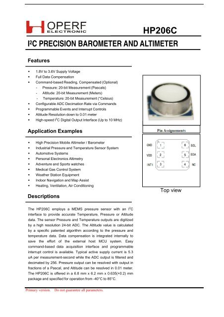
2. Function Descriptions<strong>HP206C</strong>GENERALThe <strong>HP206C</strong> is a high precision barometer and altimeterthat measures the pressure and the temperature by aninternal 24‐bit ADC and compensates them by apatented algorithm. The fully‐compensated values canbe read out via the I 2 C interface by external MCU. Theuncompensated values can also be read out in case theuser wants <strong>to</strong> perform their own data compensation. Thedevices can also compute the valueof altitude according <strong>to</strong> the measured pressure andtemperature.Furthermore, the device allows the user <strong>to</strong> setup thetemperature, pressure and altitude threshold values forvarious events. Once the device detects that a certainevent has happened, a corresponding interrupt will begenerated and sent <strong>to</strong> the external MCU. Also, multipleuseful interrupt options are available <strong>to</strong> be used by theuser.FACTORY CALIBRATIONEvery device is individually fac<strong>to</strong>ry calibrated forsensitivity and offset for both of the temperature andpressure measurements. The trim values are s<strong>to</strong>red inthe on‐chip 128‐Byte Non‐Volatile Memory (NVM). Innormal situation, further calibrations are not necessary<strong>to</strong> be done by the user. However, in order <strong>to</strong> realize thehighest possible accuracy, the device allows the users <strong>to</strong>burn their own trim values in<strong>to</strong> the empty bank of theNVM using the provided CMOSTEK NVM PROGRAMMER.Once a new bank of the NVM is programmed, theoriginal fac<strong>to</strong>ry calibrated trim values will be replaced bythe newly programmed trim values.Please refer <strong>to</strong> the document of AN301 for the details ofNVM programming and the AN302 for the details ofcomputing the correct trim values for each differentdevice.AUTOMATIC POWER-UPOnce the device detects a valid VDD is externallysupplied, an internal Power‐On‐Reset (POR) is generatedand the device will au<strong>to</strong>matically enter the power‐upinitialization sequence. After that the device will enterthe sleep state. Normally the entire power‐up sequenceconsumes about 400 us.The user can scan a DEV_RDY bit in the INT_SRC registerin order <strong>to</strong> know whether the device has finished itspower‐up sequence. This bit appears <strong>to</strong> 1 when thesequence is done. The device stays in the sleep stateunless it receives a proper command from the externalMCU. This will help <strong>to</strong> achieve minimum powerconsumptions.SENSOR OUTPUT CONVERSIONFor each pressure measurement, the temperature isalways being measured prior <strong>to</strong> pressure measurementau<strong>to</strong>matically, while the temperature measurement canbe done individually. The conversion results are s<strong>to</strong>redin<strong>to</strong> the embedded memories that retain their contentswhen the device is in the sleep state.The conversion time depends on the value of the DSRparameter sent <strong>to</strong> the device within the ADC_CVTcommand. Six options of the DSR can be chosen, rangefrom 128, 256 … <strong>to</strong> 4096. The below table shows theconversion time according <strong>to</strong> the different values ofDSR:Table 6: Conversion Time VS DSRConversion Time (ms)DSRTemperature andTemperature OnlyPressure (or Altitude)128 2.1 4.1256 4.1 8.2512 8.2 16.41024 16.4 32.82048 32.8 65.64096 65.6 131.1The higher DSR will normally achieve higher measuringprecision, but consume more time and power.The conversion results can be compensated oruncompensated. The user can enable/disable thecompensation by setting the PARA register beforeperforming the conversions.ALTITUDE COMPUTATIONThe device can compute the altitude according <strong>to</strong> themeasured pressure and temperature. The altitude valueis updated and available <strong>to</strong> read as soon as thetemperature and pressure measurement is done.3
<strong>HP206C</strong>The 3 rd TYPE: the host reading a register from the device1 1 1 0 1 1 10 0 1 0 0 0 0 1 1 0 0S Device Address W A Command A PBit Descriptions1 1 1 0 1 1 10 0 1 0 0 1 0 1 1 0 1S Device Address R A Data N PThe 4 th TYPE: the host reading the 3‐byte or 6‐byte ADC data from the device1 1 1 0 1 1 10 0 0 0 0 0 0 1 1 0 0S Device Address W A Command A PFrom HostFrom ChipS Start Bit P S<strong>to</strong>p BitW WriteR ReadA ACK N NACK1 1 1 0 1 1 10 0 0 1 0 0 0 1 1 0 0S Device Address R A Data Byte 6 or 3 A0 0 1 1 0 1 0 0 1Data Byte 0N PNote: the Device Address is 0XEC.5. Control RegistersThe control registers allow the user <strong>to</strong> set the thresholdvalues for various event detections, configure theinterrupt setting, and enable/disable the datacompensation. It is recommended for the user <strong>to</strong> setthese registers <strong>to</strong> the desired values before performingthe conversions or any other command‐basedoperations. The following is a table of all the controlregisters.The registers from 0x00 <strong>to</strong> 0x0A are designed for theuser <strong>to</strong> setup the parameters (offset and thresholds) forpressure (or altitude) and temperature eventdetections. The registers from 0x0B <strong>to</strong> 0x0D are used forinterrupt controls. The register of 0x0E is dedicated forswitching on/off the sensor output compensationfunction inside the device.Table 9: Control Registers ListAddr Name Default Bit 7 Bit 6 Bit 5 Bit 4 Bit 3 Bit 2 Bit 1 Bit 00x00 ALT_OFF_LSB 0x00 ALT_OFF [7:0]0x01 ALT_OFF_MSB 0x00 ALT_OFF [15:8]0x02 PA_H_TH_LSB 0x00 PA_H_TH [7:0]0x03 PA_H_TH_MSB 0x00 PA_H_TH [15:8]0x04 PA_M_TH_LSB 0x00 PA_M_TH [7:0]0x05 PA_M_TH_MSB 0x00 PA_M_TH [15:8]0x06 PA_L_TH_LSB 0x00 PA_L_TH [7:0]0x07 PA_L_TH_MSB 0x00 PA_L_TH [15:8]0x08 T_H_TH 0x00 T_H_TH [7:0]0x09 T_M_TH 0x00 T_M_TH [7:0]0x0A T_L_TH 0x00 T_L_TH [7:0]0x0B INT_EN 0x00 Reserved Reserved PA_RDY_EN T_RDY_EN PA_TRAV_EN T_TRAV_EN PA_WIN_EN T_WIN_EN0x0C INT_CFG 0x00 Reserved PA_MODE PA_RDY_CFG T_RDY_CFG PA_TRAV_CFG T_TRAV_CFG PA_WIN_CFG T_WIN_CFG0x0D INT_SRC 0x00 TH_ERR DEV_RDY PA_RDY T_RDY PA_TRAV T_TRAV PA_WIN T_WIN0x0E PARA 0x80 CMPS_EN Reserved Reserved Reserved Reserved Reserved Reserved Reserved6
<strong>HP206C</strong>SETUP THE ALTITUDE OFFSETCOMPENSATION PARAMETERALT_OFF_LSB, ALT_OFF_MSB ‐ (RW)The two registers form the 16‐bit value of ALT_OFF,which saves the altitude offset data used <strong>to</strong> compensatethe altitude calculation. The data is in 2’s complementformat and the unit is in centimeter. The users need <strong>to</strong>set these registers if they need <strong>to</strong> use the altitudecomputation function of the device.Normally, the values of the local average standardatmospheric pressure (P local ) may vary in different placesaround the world. The varying range is from 1000 mbar<strong>to</strong> 1026 mbar. The device requires the user <strong>to</strong> setup theALT_OFF <strong>to</strong> remove the offset. The following table isprovided <strong>to</strong> assist <strong>to</strong> finding the value of desired altitudeoffset.P local has unit in mbar, A offset has unit in meterP local 1000 1001 1002 1003A offset ‐111.18 ‐102.73 ‐94.29 ‐85.85P local 1004 1005 1006 1007A offset ‐77.43 ‐69.02 ‐60.62 ‐52.23P local 1008 1009 1010 1011A offset ‐43.84 ‐35.47 ‐27.11 ‐18.76P local 1012 1013 1014 1015A offset ‐10.41 ‐2.08 6.24 14.56P local 1016 1017 1018 1019A offset 22.86 31.15 39.44 47.71P local 1020 1021 1022 1023A offset 55.98 64.23 72.48 80.71P local 1024 1025 1026A offset 88.94 97.16 105.36If the users find out that the value of P local is an integer,they can directly obtain the corresponding altitude offsetvalue in the above table; if the P local has decimal numbersand the value is larger than P 1 and smaller than P 2 (P 1and P 2 are two adjacent pressure values in the table),the user shall first obtain the corresponding altitudeoffset value A 1 and A 2 in the table, than use either of thefollowing two formulas <strong>to</strong> calculate the desired altitudeoffset value A:A = A 1 + 8.326 x (P local – P 1 ), orA = A 2 ‐ 8.326 x (P 2 – P local )For example, the P local is 1016.4 mbar, which is between1016 mbar (P 1 ) and 1017 mbar (P 2 ). Looking up the table,A 1 is 22.86 m and A 2 is 31.15 m. Thus:A = 22.86 + 8.326 x (1016.4 – 1016) = 26.19 m, orA = 31.15 ‐ 8.326 x (1017 – 1016.4) = 26.15 mEither of the results is acceptable. After obtaining thevalue of A, no matter by looking up the table directly orby calculation, the user shall multiply the A by 100 inorder <strong>to</strong> convert the unit from meter <strong>to</strong> centimeter.Finally, convert the result <strong>to</strong> a 2’s complement number <strong>to</strong>obtain ALT_OFF, and fill it in<strong>to</strong> the two registers. Thefollowing table shows 2 examples with the calculatedaltitude offsets and their corresponding values <strong>to</strong> fill in<strong>to</strong>the two registers.Example:Offset Hex Value ALT_OFF_MSB ALT_OFF_LSB50.02 m 0x138A 0x13 0x8A-100.05 m 0XD8EB 0xD8 0xEBSETUP THE EVENTS DETECTIONPARAMETERSPA_H_TH_LSB, PA_H_TH_MSB ‐ (RW)The two registers form the 16‐bit value of PA_H_THwhich saves the pressure (or altitude) upper boundthreshold for event detection. When the PA_MODE bit inthe INT_CFG register is set <strong>to</strong> 0, the contents s<strong>to</strong>red inthese registers are the pressure thresholds. Its valueshould be a 16‐bit unsigned number and its unit is in0.02 mbar. When setting the pressure thresholds, theuser must divide the actual thresholds by 0.02, and thenconvert the result <strong>to</strong> a 2’s complement number. Whenthe PA_MODE bit is set <strong>to</strong> 1, the contents s<strong>to</strong>red in theseregisters are the altitude thresholds. Its value should bea 16‐bit 2’s complement number and its unit is in meter.Example:PA_MODE = 0 (pressure, unit in 0.02 mbar)Threshold Hex Value PA_H_TH_MSB PA_H_TH_LSB800.06 mbar 0x9C43 0x9C 0x43900 mbar 0xAFC8 0xAF 0xC8PA_MODE = 1 (altitude, unit in meter)Threshold Hex Value PA_H_TH_MSB PA_H_TH_LSB5000 m 0x1388 0x13 0x88These examples are also applied <strong>to</strong> setting the pressure(or altitude) middle and lower bound threshold registersas introduced below.PA_M_TH_LSB, PA_M_TH_MSB ‐ (RW)The two registers form the 16‐bit value of PA_M_THwhich saves the pressure (or altitude) middle thresholdfor event detection. Similar <strong>to</strong> the PA_H_TH, themeaning of their values and the data formats areselected by the PA_MODE bit.PA_L_TH_LSB, PA_L_TH_MSB ‐ (RW)The two registers form the 16‐bit value of PA_L_THwhich saves the pressure (or altitude) lower boundthreshold for event detection. Similar <strong>to</strong> the PA_H_TH,the meaning of their values and the data formats areselected by the PA_MODE bit.7
<strong>HP206C</strong>T_H_TH ‐ (RW)This register s<strong>to</strong>res the 8‐bit temperature threshold forevent detection. The data is in 2’s complement formatand the unit is in ℃.Example:Threshold Hex Value T_H_TH45℃ 0x2D 0x2D-20℃ 0xEC 0xECThese examples are also applied for setting thetemperature middle and lower bound threshold registersas introduced below.T_M_TH ‐ (RW)This register s<strong>to</strong>res the 8‐bit temperature middlethreshold for event detection. The data is in 2’scomplement format and the unit is in ℃.T_L_TH ‐ (RW)This register s<strong>to</strong>res the 8‐bit temperature lower boundthreshold for event detection. The data is in 2’scomplement format and the unit is in ℃.IMPROPER SETTING OF THRESHOLDSImproperly setting the thresholds, such as setting thelower bound threshold <strong>to</strong> be larger than the upperbound threshold, will lead <strong>to</strong> unexpected behavior of thedevice. It is recommended for the user <strong>to</strong> check thestatus of the TH_ERR bit in the INT_SRC register aftersetting the thresholds in<strong>to</strong> the device. Logic 1 of this bitindicates that improper setting of the thresholds occurs.CONFIGURE THE INTERRUPTST<strong>here</strong> are 6 interrupts that can be generated by thedevice. They are:PA_RDYIndicates that the pressure (or altitude) measurement isdone and the result is ready <strong>to</strong> read.T_RDYIndicate that the temperature measurement is done andthe result is ready <strong>to</strong> read.PA_TRAVIndicate that the pressure (or altitude) value hastraversed the middle threshold during the lastmeasurement.T_TRAVIndicate that the temperature value has traversed themiddle threshold during the last measurement.PA_WINIndicate that the pressure (or altitude) value locatesoutside the pre‐defined window (the value in betweenthe upper bound and lower bound thresholds) duringthe last measurement.T_WINIndicate that the temperature value locates outside thepre‐defined window (the value in between the upperbound and lower bound thresholds) during the lastmeasurement.The interrupt names prefixed by a ‘PA’ relate <strong>to</strong> thepressure (or altitude) measurement. The interruptnames prefixed by a ‘T’ relate <strong>to</strong> the temperaturemeasurement. These interrupts are all active‐high andwill remain high until the interrupt‐clearing conditionshappen. The interrupt‐clearing conditions are that thedevice has received a new ADC result‐reading commandor a new ADC conversion command. T<strong>here</strong> are threeregisters available for the interrupt controls as shownbelow.INT_EN ‐ (RW)The INT_EN register allows the user <strong>to</strong> disable/enableeach of the 6 interrupts (0: disable, 1: enable). When theusers need enable the traversal or window interrupt,they must also enable the corresponding PA_RDY_EN orT_RDY_EN bit.INT_CFG ‐ (RW)The INT_CFG register allows the user <strong>to</strong> select whether<strong>to</strong> output the interrupts from the INT1 pin (0: do no<strong>to</strong>utput, 1: output). The register also contains a controlbit ‘PA_MODE’ that selects whether the event detectionparameters and the interrupts registers prefixed by a‘PA_’ corresponds <strong>to</strong> the pressure or the altitudemeasurement (0: pressure, 1: altitude).INT_SRC ‐ (Read‐only)The INT_SRC register contains the interrupt flags thatallow the user <strong>to</strong> know the interrupts status, as well as adevice status bit ‘DEV_RDY’ that tells whether the deviceis ready for access or not. The device is ready when it isin the sleep state and is not performing the power‐upsequence, the data conversions, and any othercommand‐based operations. The external MCU shallonly access <strong>to</strong> the device while the device is ready(DEV_RDY = 1).If the INT_CFG bit is set <strong>to</strong> 0 while the INT_EN bit is set<strong>to</strong> 1, the corresponding interrupt flag will appear in theINT_SRC register but the interrupt will not be output <strong>to</strong>the INT1 pin.ENABLE THE COMPENSATIONPARA ‐ (RW)This register has only one valid bit of CMPS_EN. The usercan use this bit <strong>to</strong> determine whether <strong>to</strong> enable the datacompensation during the conversion process (0: disable,1: enable). If it is enabled, the 24‐bit or 48‐bit data readout by the commands are fully compensated. If it isdisabled, the data read out are the raw data output.8
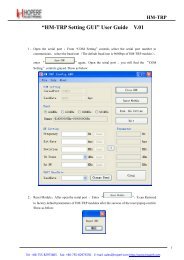
6. PACKAGE INFORMATION<strong>HP206C</strong>Mechanical Dimension (unit: mm)9
7. Document His<strong>to</strong>ry<strong>HP206C</strong>Version No. Revisions DateV1.0 First released version 2013.5.21V1.1 Modify PIN define and error description 2013.8.2Importance Note:Primary version, we do not guarantee all parameters in this <strong>datasheet</strong>10