RF50 Demo V1.1
RF50 Demo V1.1
RF50 Demo V1.1

Create successful ePaper yourself
Turn your PDF publications into a flip-book with our unique Google optimized e-Paper software.
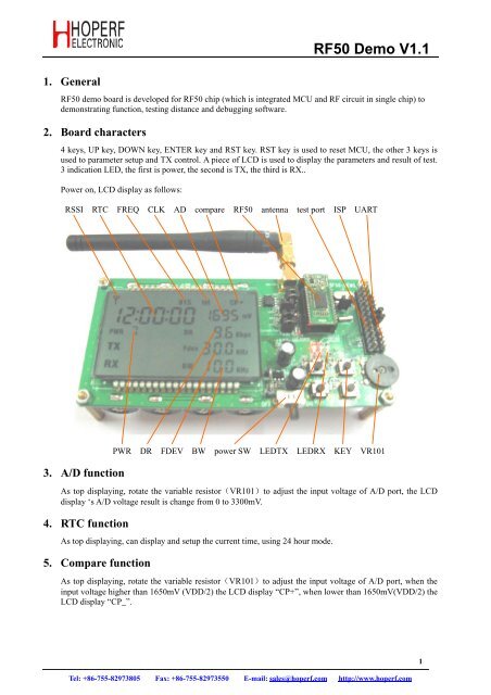
1. General<strong>RF50</strong> <strong>Demo</strong> <strong>V1.1</strong><strong>RF50</strong> demo board is developed for <strong>RF50</strong> chip (which is integrated MCU and RF circuit in single chip) todemonstrating function, testing distance and debugging software.2. Board characters4 keys, UP key, DOWN key, ENTER key and RST key. RST key is used to reset MCU, the other 3 keys isused to parameter setup and TX control. A piece of LCD is used to display the parameters and result of test.3 indication LED, the first is power, the second is TX, the third is RX..Power on, LCD display as follows:RSSI RTC FREQ CLK AD compare <strong>RF50</strong> antenna test port ISP UART3. A/D functionPWR DR FDEV BW power SW LEDTX LEDRX KEY VR101As top displaying, rotate the variable resistor(VR101)to adjust the input voltage of A/D port, the LCDdisplay ‘s A/D voltage result is change from 0 to 3300mV.4. RTC functionAs top displaying, can display and setup the current time, using 24 hour mode.5. Compare functionAs top displaying, rotate the variable resistor(VR101)to adjust the input voltage of A/D port, when theinput voltage higher than 1650mV (VDD/2) the LCD display “CP+”, when lower than 1650mV(VDD/2) theLCD display “CP_”.Tel: +86-755-82973805 Fax: +86-755-82973550 E-mail: sales@hoperf.com http://www.hoperf.com1
6. UART functionCan transmit testing information, error information and received RF data to UART port.7. Timer functionIn demo code have a 1ms timer.8. Interrupt functionThis function is used in any other functions testing.9. Clock source function<strong>RF50</strong> <strong>Demo</strong> <strong>V1.1</strong>Can select the <strong>RF50</strong> working with internal OSC or external OSC. When select external OSC, the jumperJ104 and J105 must connect to left..10. RF transceiver functionMust connect jumper J102. Working in normal mode, when press UP、DOWN、ENTER key on one DEMOboard it will transmit RF data, the TX LED will flash once. When receive back data the RX LED will alsoflash once. The LCD display the transmited RF data and the received back data (every have two bytes, thefirst byte is key code, the second byte is key pressed times), also display the received RF signal strength.The LCD display as follows:TX dataRX dataTel: +86-755-82973805 Fax: +86-755-82973550 E-mail: sales@hoperf.com http://www.hoperf.com2
<strong>RF50</strong> <strong>Demo</strong> <strong>V1.1</strong>When press UP、DOWN、ENTER key on the other DEMO board to transmit RF data., this DEMO board’sRX LED will flash once if received data, then transmit the received data, the TX LED will flash once at thetime. The LCD display the received data (two bytes the first byte is key code, the second byte is key pressedtimes), also display the received RF signal strength. The LCD display as follows:Tel: +86-755-82973805 Fax: +86-755-82973550 E-mail: sales@hoperf.com http://www.hoperf.com3
<strong>RF50</strong> <strong>Demo</strong> <strong>V1.1</strong>12. PCB pictureTop viewBottom viewSW101J101J102J103J104,J105J106,J107VR101Power switch, ON position turn on powerCurrent testMust connect the jumper if RF transceiver is testedMust connect the jumper if UART supply powerClock select, connect the jumpers to left when using external OSCEEPROM select, connect the jumpers when using external EEPROMAdjust the voltage on AD port13. Circuit picture ( Page 6 )5Tel: +86-755-82973805 Fax: +86-755-82973550 E-mail: sales@hoperf.com http://www.hoperf.com