Sensors & Transducers - International Frequency Sensor Association
Sensors & Transducers - International Frequency Sensor Association
Sensors & Transducers - International Frequency Sensor Association

Create successful ePaper yourself
Turn your PDF publications into a flip-book with our unique Google optimized e-Paper software.
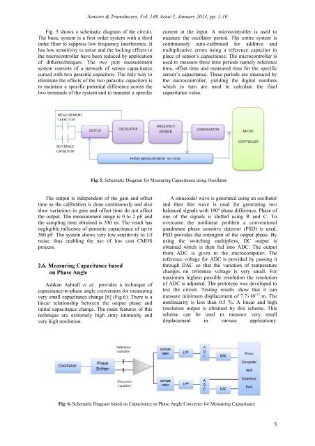
<strong><strong>Sensor</strong>s</strong> & <strong>Transducers</strong>, Vol. 148, Issue 1, January 2013, pp. 1-10Fig. 5 shows a schematic diagram of the circuit.The basic system is a first order system with a thirdorder filter to suppress low frequency interference. Ithas low sensitivity to noise and the locking effects tothe microcontroller have been reduced by applicationof dithertechniques. The two port measurementsystem consists of a network of sensor capacitancecursed with two parasitic capacitors. The only way toeliminate the effects of the two parasitic capacitors isto maintain a specific potential difference across thetwo terminals of the system and to transmit a specificcurrent at the input. A microcontroller is used tomeasure the oscillator period. The entire system iscontinuously auto-calibrated for additive andmultiplicative errors using a reference capacitor inplace of sensor’s capacitance. The microcontroller isused to measure three time periods namely referencetime, offset time and measured time for the specificsensor’s capacitance. These periods are measured bythe microcontroller, yielding the digital numberswhich in turn are used to calculate the finalcapacitance value.Fig. 5. Schematic Diagram for Measuring Capacitance using Oscillator.The output is independent of the gain and offsettime as the calibration is done continuously and alsoslow variations in gain and offset time do not affectthe output. The measurement range is 0 to 2 pF andthe sampling time obtained is 330 ns. The result hasnegligible influence of parasitic capacitance of up to300 pF. The system shows very low sensitivity to 1/fnoise, thus enabling the use of low cost CMOSprocess.2.6. Measuring Capacitance basedon Phase AngleAshkan Ashrafi et al., provides a technique ofcapacitance-to-phase angle conversion for measuringvery small capacitance change [6] (Fig.6). There is alinear relationship between the output phase andinitial capacitance change. The main features of thistechnique are extremely high stray immunity andvery high resolution.A sinusoidal wave is generated using an oscillatorand then this wave is used for generating twobalanced signals with 180º phase difference. Phase ofone of the signals is shifted using R and C. Toovercome the nonlinear problem a conventionalquadrature phase sensitive detector (PSD) is used.PSD provides the cotangent of the output phase. Byusing the switching multipliers, DC output isobtained which is then fed into ADC. The outputfrom ADC is given to the microcomputer. Thereference voltage for ADC is provided by passing itthrough DAC so that the variation of temperaturechanges on reference voltage is very small. Formaximum highest possible resolution the resolutionof ADC is adjusted. The prototype was developed totest the circuit. Testing results show that it canmeasure minimum displacement of 7.710 -12 m. Thenonlinearity is less than 0.5 %. A linear and highresolution output is obtained by this scheme. Thisscheme can be used to measure very smalldisplacement in various applications.Fig. 6. Schematic Diagram based on Capacitance to Phase Angle Converter for Measuring Capacitance.5