Sensors & Transducers - International Frequency Sensor Association
Sensors & Transducers - International Frequency Sensor Association
Sensors & Transducers - International Frequency Sensor Association

Create successful ePaper yourself
Turn your PDF publications into a flip-book with our unique Google optimized e-Paper software.
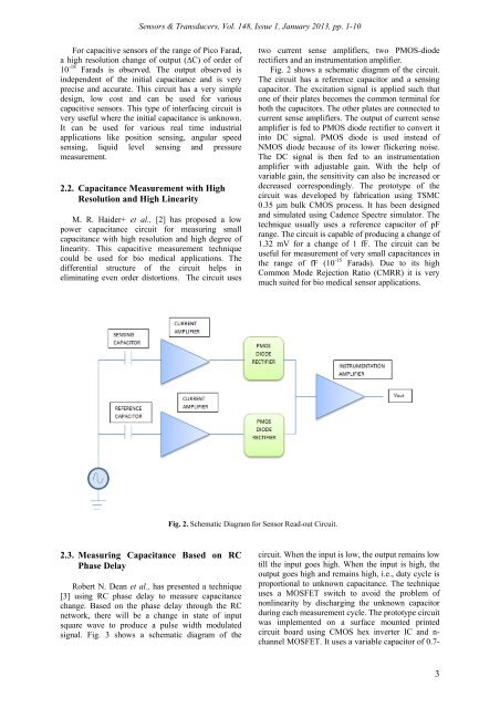
<strong><strong>Sensor</strong>s</strong> & <strong>Transducers</strong>, Vol. 148, Issue 1, January 2013, pp. 1-10For capacitive sensors of the range of Pico Farad,a high resolution change of output (∆C) of order of10 -18 Farads is observed. The output observed isindependent of the initial capacitance and is veryprecise and accurate. This circuit has a very simpledesign, low cost and can be used for variouscapacitive sensors. This type of interfacing circuit isvery useful where the initial capacitance is unknown.It can be used for various real time industrialapplications like position sensing, angular speedsensing, liquid level sensing and pressuremeasurement.2.2. Capacitance Measurement with HighResolution and High LinearityM. R. Haider+ et al., [2] has proposed a lowpower capacitance circuit for measuring smallcapacitance with high resolution and high degree oflinearity. This capacitive measurement techniquecould be used for bio medical applications. Thedifferential structure of the circuit helps ineliminating even order distortions. The circuit usestwo current sense amplifiers, two PMOS-dioderectifiers and an instrumentation amplifier.Fig. 2 shows a schematic diagram of the circuit.The circuit has a reference capacitor and a sensingcapacitor. The excitation signal is applied such thatone of their plates becomes the common terminal forboth the capacitors. The other plates are connected tocurrent sense amplifiers. The output of current senseamplifier is fed to PMOS diode rectifier to convert itinto DC signal. PMOS diode is used instead ofNMOS diode because of its lower flickering noise.The DC signal is then fed to an instrumentationamplifier with adjustable gain. With the help ofvariable gain, the sensitivity can also be increased ordecreased correspondingly. The prototype of thecircuit was developed by fabrication using TSMC0.35 μm bulk CMOS process. It has been designedand simulated using Cadence Spectre simulator. Thetechnique usually uses a reference capacitor of pFrange. The circuit is capable of producing a change of1.32 mV for a change of 1 fF. The circuit can beuseful for measurement of very small capacitances inthe range of fF (10 -15 Farads). Due to its highCommon Mode Rejection Ratio (CMRR) it is verymuch suited for bio medical sensor applications.Fig. 2. Schematic Diagram for <strong>Sensor</strong> Read-out Circuit.2.3. Measuring Capacitance Based on RCPhase DelayRobert N. Dean et al., has presented a technique[3] using RC phase delay to measure capacitancechange. Based on the phase delay through the RCnetwork, there will be a change in state of inputsquare wave to produce a pulse width modulatedsignal. Fig. 3 shows a schematic diagram of thecircuit. When the input is low, the output remains lowtill the input goes high. When the input is high, theoutput goes high and remains high, i.e., duty cycle isproportional to unknown capacitance. The techniqueuses a MOSFET switch to avoid the problem ofnonlinearity by discharging the unknown capacitorduring each measurement cycle. The prototype circuitwas implemented on a surface mounted printedcircuit board using CMOS hex inverter IC and n-channel MOSFET. It uses a variable capacitor of 0.7-3