Sensors & Transducers - International Frequency Sensor Association
Sensors & Transducers - International Frequency Sensor Association
Sensors & Transducers - International Frequency Sensor Association

Create successful ePaper yourself
Turn your PDF publications into a flip-book with our unique Google optimized e-Paper software.
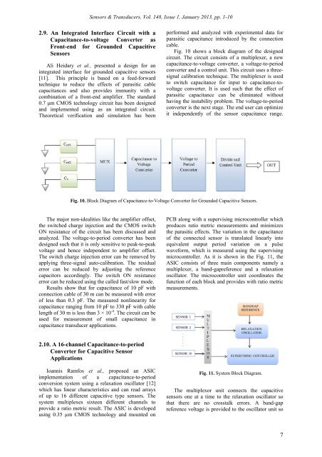
<strong><strong>Sensor</strong>s</strong> & <strong>Transducers</strong>, Vol. 148, Issue 1, January 2013, pp. 1-102.9. An Integrated Interface Circuit with aCapacitance-to-voltage Converter asFront-end for Grounded Capacitive<strong><strong>Sensor</strong>s</strong>Ali Heidary et al., presented a design for anintegrated interface for grounded capacitive sensors[11]. This principle is based on a feed-forwardtechnique to reduce the effects of parasitic cablecapacitances and also provides immunity with acombination of a front-end amplifier. The standard0.7 μm CMOS technology circuit has been designedand implemented using as an integrated circuit.Theoretical verification and simulation has beenperformed and analyzed with experimental data forparasitic capacitance introduced by the connectioncable.Fig. 10 shows a block diagram of the designedcircuit. The circuit consists of a multiplexer, a newcapacitance-to-voltage converter, a voltage-to-periodconverter and a control unit. This circuit uses a threesignalcalibration technique. The multiplexer is usedto switch capacitance for input to capacitance-tovoltageconverter. It is used such that the effect ofparasitic capacitance can be eliminated withouthaving the instability problem. The voltage-to-periodconverter is the next stage. The end user can optimizeit independently of the sensor capacitance range.Fig. 10. Block Diagram of Capacitance-to-Voltage Converter for Grounded Capacitive <strong><strong>Sensor</strong>s</strong>.The major non-idealities like the amplifier offset,the switched charge injection and the CMOS switchON resistance of the circuit has been discussed andanalyzed. The voltage-to-period converter has beendesigned such that it is only sensitive to peak-to-peakvoltage and hence independent to amplifier offset.The switch charge injection error can be removed byapplying three-signal auto-calibration. The residualerror can be reduced by adjusting the referencecapacitors accordingly. The switch ON resistanceerror can be reduced using the called fast/slow mode.Results show that for capacitance of 10 pF withconnection cable of 30 m can be measured with errorof less than 0.3 pF. The measured nonlinearity forcapacitance ranging from 10 pF to 330 pF with cablelength of 30 m is less than 3 × 10 -4 . The circuit can beused for measurement of small capacitance incapacitance transducer applications.PCB along with a supervising microcontroller whichproduces ratio metric measurements and minimizesthe parasitic effects. The variation in the capacitanceof the connected sensor is translated linearly intoequivalent output period variation on a pulsewaveform, which is measured using the supervisingmicrocontroller. As it is shown in the Fig. 11, theASIC consists of three main components namely amultiplexer, a band-gapreference and a relaxationoscillator. The microcontroller unit coordinates thefunction of each block and provides with ratio metricmeasurements.2.10. A 16-channel Capacitance-to-periodConverter for Capacitive <strong>Sensor</strong>ApplicationsIoannis Ramfos et al., proposed an ASICimplementation of a capacitance-to-periodconversion system using a relaxation oscillator [12]which has linear characteristics and can read arraysof up to 16 different capacitive type sensors. Thesystem multiplexes sixteen different channels toprovide a ratio metric result. The ASIC is developedusing 0.35 µm CMOS technology and mounted onFig. 11. System Block Diagram.The multiplexor unit connects the capacitivesensors one at a time to the relaxation oscillator sothat there are no crosstalk errors. A band-gapreference voltage is provided to the oscillator unit so7