Comparison Between OOK/ASK and FSK Modulation Techniques
Comparison Between OOK/ASK and FSK Modulation Techniques
Comparison Between OOK/ASK and FSK Modulation Techniques

Create successful ePaper yourself
Turn your PDF publications into a flip-book with our unique Google optimized e-Paper software.
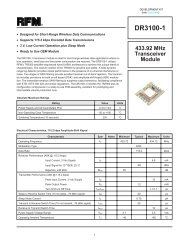
A COMPARISON BETWEEN<strong>OOK</strong>/<strong>ASK</strong> AND <strong>FSK</strong> MODULATION TECHNIQUES FOR RADIO LINKSDARRELL L. ASHRF MONOLITHICS, INC., DALLAS, TEXASINTRODUCTIONShort range unlicensed radio links, with typical ranges of 1 to 100 meters, are becoming more <strong>and</strong> more popular. Millions of theseradios are used today in such applications as automotive keyless entry, tire pressure monitoring, gate openers, wireless securitysystems, data links, remote meter reading <strong>and</strong> too many other applications to enumerate. With the number of short range devices(SRD’s) increasing daily, the potential for interference by competing nearby SRD’s or other wireless services has increaseddramatically over the last few years. It is becoming more <strong>and</strong> more important for SRD’s to be capable of reusing the samespectrum shared by other SRD’s. To share the same spectrum, radio receivers must ignore co-channel interfering signals that areweaker than the desired signal. Such a receiver exhibits what is commonly referred to as the “capture effect”. The term “captureeffect” is commonly associated with FM or <strong>FSK</strong> receivers <strong>and</strong> not with <strong>OOK</strong>/<strong>ASK</strong> by the industry in general. The industry alsobelieves that <strong>FSK</strong> receivers are more sensitive than <strong>OOK</strong> receivers. This paper will show that, when properly implemented, <strong>OOK</strong>can actually outperform <strong>FSK</strong> in both the areas of sensitivity <strong>and</strong> co-channel interference tolerance.<strong>OOK</strong>/<strong>FSK</strong> CONSIDERATIONSBefore making the decision whether to use <strong>OOK</strong> or <strong>FSK</strong> for an application, several factors, other than sensitivity <strong>and</strong> co-channelinterference, should be carefully considered. A good example is the b<strong>and</strong>width required to transmit data with <strong>OOK</strong> modulationversus that required with <strong>FSK</strong> modulation. In the case of <strong>FSK</strong>, using the minimum criteria for good noise performance, theb<strong>and</strong>width needed is 1.5 times that required for <strong>OOK</strong> [1]. This is a very important consideration in the new limited b<strong>and</strong>widthETSI SRD b<strong>and</strong>s at 868 MHz.The simplicity of the <strong>OOK</strong> transmitter is without equal. Either the stabilized oscillator in the transmitter or a buffer amplifier onits output is simply turned on <strong>and</strong> off in synchronization with the data to be transmitted. One very important result of using thistype of modulation is at least a 50% reduction in battery current drain when compared to that consumed by an <strong>FSK</strong> transmitter.The <strong>FSK</strong> transmitter must be on 100% of the time that data is being transferred.The implementation of the <strong>FSK</strong> transmitter requires accurate control of both the center frequency <strong>and</strong> the frequency deviation. Asa result, the preferred implementation requires a frequency synthesizer <strong>and</strong> a bulk crystal for stability. Many of the SRDapplications, such as tire pressure monitoring, involve rapid temperature cycling over temperature extremes (-40 to +85 degrees C)as well as severe shock <strong>and</strong> vibration. Bulk crystals are inherently fragile. They also usually require compensation in theoscillator circuit to operate over large temperature excursions. On the other h<strong>and</strong>, an <strong>OOK</strong> transmitter can be implemented using aSAW resonator <strong>and</strong> a simple oscillator circuit. The SAW resonator is easily capable of h<strong>and</strong>ling the temperature, shock <strong>and</strong>vibration extremes of such applications.The implementation of the <strong>FSK</strong> receiver also requires accurate frequency control so a frequency synthesizer <strong>and</strong> bulk crystal mustbe used. In addition, the demodulation of the transmitted <strong>FSK</strong> signal requires another accurate frequency reference for thediscriminator or phase locked loop. This is not the case with an <strong>OOK</strong> receiver.<strong>OOK</strong> VERSUS <strong>FSK</strong> SENSITIVITYOptimum sensitivity for either an <strong>OOK</strong> or an <strong>FSK</strong> receiver is obtained using a coherent or synchronous demodulator. This can beimplemented using a phase locked loop (PLL) demodulator for either <strong>OOK</strong> or <strong>FSK</strong>. The tune voltage for the VCO (locked to theRF carrier) in the PLL can be used as the demodulated <strong>FSK</strong> data. <strong>OOK</strong> is demodulated by inserting the output of the VCO as oneinput to a multiplier <strong>and</strong> the RF carrier as the other input. The output of the multiplier is 2X the input frequency <strong>and</strong> the DC termwhich is the desired <strong>OOK</strong> data. A pseudo-synchronous <strong>OOK</strong> demodulator, with little or no degradation over a true synchronousdemodulator, can be implemented simply by applying the incoming RF signal to both input ports of a multiplier. Referring toFigure 1, this is the technique used in RFM’s ASH receiver for demodulating signals from the noise level to 20 dB above the noiselevel. This type of <strong>OOK</strong> demodulator is much simpler to implement than the PLL approach.
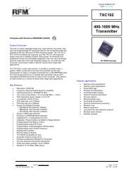
CNTRL1CNTRL0AntennaRFIO20ESDChokeSAWCR FilterVCC1: Pin 2VCC2: Pin 16GND1: Pin 1GND2: Pin 10GND3: Pin 19NC: Pin 8RREF: Pin 11CMPIN: Pin 6RFA117 18Bias ControlSAWDelay LinePowerDownControlRFA2RSSIDetectorRFA2LPFADJLow-PassFilter9R LPFBBBBOUTRefPeak5 6 DetectorC BBOPKDET 4C PKDAGCDS2dB BelowPeak ThldDS1AND7RXDATARefThldAGC SetGain SelectThresholdControl13 11 12THLD1THLD2Pulse Generator& RF Amp BiasAGCControlAGC ResetR TH1R REFR TH2PRATE 14 15 PWIDTH AGCCAP 3C AGCR PRR PWFigure 12 nd Generation ASH Receiver Block DiagramThe best way to compare the sensitivity or range of <strong>OOK</strong> <strong>and</strong> <strong>FSK</strong> radio receivers is to look at the bit error rate of the receiverversus the signal to noise ratio of the incoming signal. The approach taken in this paper to make this comparison was developedby Peebles in his book Digital Communication Systems [2].The energy over one data bit interval is:E = A 2 T b /2 (1)where A is the amplitude of the signal <strong>and</strong> T b is the time for one bit. The average energy per bit divided by twice the channel noisedensity N 0 is:ε = A 2 T b /4N 0 (2)Thus, for coherent <strong>OOK</strong> <strong>and</strong> coherent <strong>FSK</strong>, the probability of bit errors P e is:P e = (1/2)erfc[(ε/2) 1/2 ] (3)where erfc[ ] is the well known complimentary error function as outlined by Peebles in Appendix F of his book.The probability of bit errors for non-coherent <strong>FSK</strong> is:P e = (1/2)exp(-ε/2) (4)Equations 3 <strong>and</strong> 4 are plotted in Figure 2.Referring to Figure 2, the non-coherent <strong>FSK</strong>example is approximately 1 dB poorer thancoherent <strong>OOK</strong> <strong>and</strong> <strong>FSK</strong>. The majority of the<strong>FSK</strong> receivers used by the industry are noncoherent,using a frequency discriminator with alow frequency resonator as the frequencyreference. From these plots, we find that thecoherent <strong>OOK</strong> receiver, as exemplified by thereceiver of Figure 1, exhibits a lower probabilityof error versus signal to noise ratio than themajority of the <strong>FSK</strong> receivers implemented. TheProbability of Error1.00E+001.00E-011.00E-021.00E-031.00E-041.00E-051.00E-061.00E-071.00E-081.00E-090 4 8 12 16Signal to Noise in dBCoherent<strong>OOK</strong> & <strong>FSK</strong><strong>FSK</strong>NoncoherentFigure 2Error Probability Versus Signal to Noise Ratio
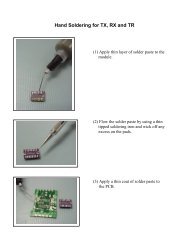
probability of error versus signal to noise ratio for the coherent <strong>OOK</strong> receiver is identical to that for the coherent <strong>FSK</strong> receiver.Thus, we conclude there is no sensitivity or range advantage to implementing the more complicated <strong>FSK</strong> radio link rather than asimple <strong>OOK</strong> radio link.<strong>OOK</strong> VERSUS <strong>FSK</strong> CO-CHANNEL INTERFERENCEAs mentioned earlier, the term “capture effect” is commonly associated with the ability of a receiver to ignore co-channelinterfering signals that are weaker than the desired signal. Analog FM receivers are far superior to analog AM receivers whenexposed to co-channel interference. Capture in an analog FM receiver is measured by a quantity called the “capture ratio”. Forpractical purposes this is the ratio in dB of wanted to unwanted signal that will cause a 30 dB suppression of the unwanted signal atthe detector output. Typical values for good quality receivers lie between 1 <strong>and</strong> 2 dB [3]. Analog AM receivers do not exhibit thisbehavior.The performance of digital FM <strong>and</strong> AM radio receivers, <strong>FSK</strong> <strong>and</strong> <strong>OOK</strong>, is much different than that of analog radio receivers. Letus consider the plots of Figure 2 in this context. The curve describing the probability of error versus signal to noise ratio (SNR)for coherent <strong>OOK</strong> <strong>and</strong> <strong>FSK</strong> shows clearly that the probability of error decreases by approximately an order of magnitude when theSNR is increased from 12 dB to 13 dB. Thus, for a change in SNR of only 1 dB, the probability of error is decreased by a factor of10. The decrease is a factor of 100 for a 2 dB change in SNR from 12 dB to 14 dB. This is similar to the “capture effect” of theanalog FM radio, but it applies to both <strong>OOK</strong> <strong>and</strong> <strong>FSK</strong> digital radios.Now let us compare the measured co-channelinterference performance of the referenced RFM <strong>OOK</strong>receiver to a commonly available single chip <strong>FSK</strong>receiver. The data taken is plotted in Figure 3. The<strong>OOK</strong> receiver was characterized with both CW <strong>and</strong><strong>OOK</strong> interference. Using either CW or <strong>FSK</strong>interfering signals gave the same results with the <strong>OOK</strong>receiver. The <strong>FSK</strong> receiver was tested with CWinterference only, since tests with <strong>FSK</strong> <strong>and</strong> <strong>OOK</strong>interference gave approximately the same results asCW. The “Y” axis of Figure 3 is the difference in dBbetween the desired signal level <strong>and</strong> the level of theinterfering signal that could be h<strong>and</strong>led without loss ofDesired toInterference Delta(dB)Desired Signal Level (dBm)the desired data. The “X” axis is the level of the desired signal in dBm. Of course, the goal is that the receiver be able to functionwith the interfering signal as close to the desired signal level as possible. The desired signal level range of most interest includes -90 to -40 dBm. These are the signal levels most commonly encountered in actual radio links. Levels above -40 dBm are onlyencountered when the transmitter is less than a meter from the receiver.Referring to Figure 3, note that the best performance for the <strong>OOK</strong> receiver was obtained with CW or <strong>FSK</strong> interference. At thedesired signal levels of -85 <strong>and</strong> -90 dBm, the interfering signal was just a few tenths of a dB from the desired level. The worstcase was -2.5 dB at a desired level of -20 dBm. This is excellent performance <strong>and</strong> indicates that such an <strong>OOK</strong> receiver wouldwork extremely well in the presence of <strong>FSK</strong> co-channel interference. The performance of the <strong>OOK</strong> receiver with <strong>OOK</strong>interference was also very good. At -90 dBm the interference was 2.5 dB below the desired level. The worst case was at a desiredlevel of -20 dBm where the difference was 9 dB. The best performance was at a desired level of 60 dBm where the differencewas 1.5 dB. In comparison, the <strong>FSK</strong> receiver performance at -90 dBm showed an 8 dB difference with the best performance at -60dBm at a difference of 3 dB.Referring to Figure 3, the co-channel performance of the <strong>OOK</strong> receiver is superior to the <strong>FSK</strong> receiver with CW or <strong>FSK</strong>interference at all desired signal levels. With <strong>OOK</strong> interference, the <strong>OOK</strong> receiver is overall better than or equivalent to the <strong>FSK</strong>receiver over the desired signal range of -90 to -40 dBm. Note that at -90 dBm the <strong>OOK</strong> has an advantage of 5.5 dB <strong>and</strong> at -60dBm the <strong>OOK</strong> advantage is 1.5 dB.0-2-4-6-8-10<strong>OOK</strong>(CW Interf)<strong>FSK</strong>(CW Interf)<strong>OOK</strong>(<strong>OOK</strong> Interf)-100 -80 -60 -40 -20 0Figure 3Capture Effect for <strong>OOK</strong> <strong>and</strong> <strong>FSK</strong>
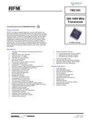
PRACTICAL EXAMPLE: <strong>OOK</strong> VERSUS <strong>FSK</strong> FOR TIRE PRESSURE MONITORINGAn SRD application that is presentlyreceiving a great deal of attention isautomotive tire pressure <strong>and</strong>temperature monitoring. Data isperiodically transmitted from thetires to a central receiver in the car.The transmitters in the tires are in avery harsh environment. The tirescan get very hot after high speeddriving over long distances. Thetires experience severe shock <strong>and</strong>vibration when traversing roughroadways. Transmitters in the tiresalso experience high centrifugalPeak ReferencedComparator OutFixed ReferenceComparator Outforces. As mentioned earlier, this is a very difficult environment for a transmitter using a bulk crystal for the frequency reference.The reliability of such a transmitter in this environment would be highly questionable, whereas a simple SAW based <strong>OOK</strong>transmitter in this application is very reliable.One problem encountered in this application that has led some in the industry to look more seriously at <strong>FSK</strong> rather than <strong>OOK</strong> iscommonly referred to as flutter. Simply defined, flutter is the variation in the level of the transmitted signal as the tire rotates. Thesignal is usually minimum when the transmitter is close to the ground <strong>and</strong> maximum when the transmitter reaches the highest pointabove the ground. This can be closely simulated in the laboratory by superimposing a sinusoidal variation in amplitude upon thetransmitted RF carrier. The limiting IF amplifier in an <strong>FSK</strong> receiver can help smooth out the amplitude variation if the minimumsignal level observed is of sufficient amplitude for good limiting.A properly implemented <strong>OOK</strong> receiver will continue to output good data even with signal levels dropping as low as the sensitivitylevel of the receiver. An example will be presented here that represents a worst case condition. The highest flutter rate will beexperienced with a small diameter tire running at the highest expected speed. A 24 inch (61 cm) tire is an example of a very smalldiameter tire. In Europe, it is possible the speed could be as high as 160 miles per hour (257.5 km per hour). In this example, sucha tire would require 26.77 ms for one complete revolution. Thus, the variation in signal level can be simulated by using 37 Hzsinusoidal amplitude modulation of the RF carrier. The most popular data rate being used is 9600 bits per second. An HP8657Bsignal generator was used to generate the signal. The generator wasmodulated on its pulse input (<strong>OOK</strong>) by the desired 9600 b/s data<strong>and</strong> was modulated on its AM input by a 37 Hz sine wave. Theamplitude of the 37 Hz sinusoid was increased until the modulationdepth was 30 dB to simulate severe flutter. Of course, 30 dB ismuch worse than the flutter expected to be encountered in the field.Typical flutter is expected to be 10 to 15 dB, but the desire was toshow how the <strong>OOK</strong> receiver would function with a depth of 30 dB.DS2DS1ANDGATEReceiverDATAOUTFigure 6Data Slicer CombinationA spectrum analyzer was set up to measure the depth of the flutter.Thus, the analyzer was set up for zero span to make the horizontalaxis display time rather than frequency. Figure 7 is a photograph ofthe screen of the spectrum analyzer displaying the signal withflutter applied. The vertical axis is the power level in dBm. Duringthe set up, the peak level of the signal generator was set quite high,-3 dBm, to allow noise free viewing of the 30 dB variation in signallevel produced by the flutter source. Then the signal generatoroutput was reduced to -70 dBm peak <strong>and</strong> applied to the <strong>OOK</strong>receiver input. The receiver was an RFM RX5500 designed foroperation at 433.92 MHz.Signal with 9.6 kb/s <strong>OOK</strong> <strong>Modulation</strong> <strong>and</strong> 37 Hz FlutterFigure 7Spectrum Analyzer Plot
Figure 8 is a photograph of the screen of an oscilloscopeshowing the BBOUT signal, see Figure 1, on the top trace, thedata input to the signal generator on the middle trace, <strong>and</strong> thedata output of the receiver on the bottom trace. Note thesinusoidal amplitude variation, representing flutter, on thesignal at BBOUT. Note the data output from the data slicerson the bottom trace is a good reproduction of the original dataeven at the lowest signal level. With the peak output of thesignal generator at -70 dBm <strong>and</strong> the flutter variation at 30 dB,the lowest signal level at the bottom of the sinusoid is -100dBm. Thus, the performance of the <strong>OOK</strong> receiver in thepresence of extreme flutter was excellent.The key to making the <strong>OOK</strong> receiver work with flutter is thevalue of the coupling capacitor connecting BBOUT to theslicer input. If this capacitor is too large, the overall BBOUTwaveform, shown on the top trace of Figure 8, centers itselfaround the quiescent input voltage at the slicer input. Thisproduces a slicer output that drops data at the low points of thesuperimposed sinusoidal modulation. The value of thecapacitor must be reduced to the point that the data input to theslicer remains centered around the quiescent DC voltage atthat point. This guarantees the proper output from the slicerunder flutter conditions. The value of the capacitor that wasused with the RFM receiver was .0047 µF. The exactcapacitor value is not critical. For example, the capacitor usedin this experiment had a tolerance of ±20%.(top) BBOUT (middle) Data Input to Signal Generator (bottom)<strong>OOK</strong> Receiver Data OutputFigure 8Oscilloscope PlotCONCLUSIONThe following points have been made in this paper:1. <strong>OOK</strong> transmitters are simpler than <strong>FSK</strong>;2. <strong>OOK</strong> transmitter current is 50% lower than <strong>FSK</strong>;3. SAW based <strong>OOK</strong> transmitters are more robust when exposed to extreme temperatures, vibration <strong>and</strong> shock;4. <strong>FSK</strong> transmission requires 1.5 times the b<strong>and</strong>width compared to <strong>OOK</strong>;5. <strong>OOK</strong> receivers are simpler than <strong>FSK</strong>;6. <strong>OOK</strong> receiver sensitivity is equal to or better than <strong>FSK</strong>;7. Properly implemented, <strong>OOK</strong> receiver performance in the presence of co-channel interference is generally better than <strong>FSK</strong>;8. Properly implemented, <strong>OOK</strong> receiver performance with amplitude flutter is equal to or better than <strong>FSK</strong>.In the past, <strong>OOK</strong> radio links have commonly been associated with the poor performance of superregenerative receivers <strong>and</strong> poorlyimplemented superheterodyne receivers. The simplicity of <strong>OOK</strong> has been the main drive for its application in millions of SRD’s inthe past. It has been shown in this paper that properly implemented <strong>OOK</strong> links can outperform or equal <strong>FSK</strong> links in all areas ofconcern while maintaining simplicity. An example of the simplicity of a properly implemented <strong>OOK</strong> receiver is the RFM receiverwhose performance was outlined in this paper. Figure 9 is a schematic diagram of the RFM receiver showing the externalcomponents necessary to achieve the performance illustrated in this paper.
Figure 9RFM <strong>OOK</strong> Receiver SchematicACKNOWLEDGEMENTThe author would like to thank Darren Ash for his invaluable assistance in putting this paper together.REFERENCES1. Tom McDermott, Wireless Digital Communications: Design <strong>and</strong> Theory, Tucson Amateur Packet Radio Corporation, Tucson,Arizona, 1996.2. Peyton Z. Peebles, Jr, Digital Communication Systems, Prentice-Hall, Inc., Englewood Cliffs, New Jersey, 1987.3. Herbert L. Krauss <strong>and</strong> Charles W. Bostian, Solid State Radio Engineering, John Wiley & Sons, New York, 1980.4. Frank H. Perkins, Jr, ASH Transceiver Designer’s Guide, RF Monolithics, Inc., Dallas, Texas, 1999.