DR1300A-DK - RF Monolithics, Inc.
DR1300A-DK - RF Monolithics, Inc.
DR1300A-DK - RF Monolithics, Inc.

You also want an ePaper? Increase the reach of your titles
YUMPU automatically turns print PDFs into web optimized ePapers that Google loves.
Virtual Wire ® Development Kit Manualfor<strong>DR1300A</strong>-<strong>DK</strong>Part Number: 400-1544-001a1Copyright 2002 <strong>RF</strong>M®
File: 400-1544-001a.doc2002.08.03 revVirtual Wire® Development Kit Manual for <strong>DR1300A</strong>-<strong>DK</strong>Virtual Wire® Development Kit Hardware WarrantySpecial Notices1 Virtual Wire® Development Kit Introduction1.1 Purpose of the Virtual Wire® Development Kit1.2 Intended User1.3 General Description1.4 Key Features1.5 Development Kit Contents2 Low-Power Wireless Data Communications2.1 Operational Considerations2.2 Regulations2.3 Example Applications2.4 FAQs3 Developing a Virtual Wire® Application3.1 Simulating the Application3.2 I/O and Power Considerations3.3 Communications Protocol3.4 Antenna Considerations3.5 Internal Noise Management3.6 Final Product Testing3.7 Regulatory CertificationRegulatory AuthorityProduct CertificationCertification Testing4 Installation and Operation4.1 Development Kit Assembly Instructions4.2 Data Radio BoardAntenna Options2Copyright 2002 <strong>RF</strong>M®
4.3 Protocol BoardRS232 InterfaceLED FunctionsHost Program Installation5 Theory of Operation5.1 Data Radio BoardsI/O InterfaceTR3000 ASH TransceiverSpecifications5.2 Protocol BoardI/O InterfaceRS232 InterfaceProtocol MicrocontrollerCMOS/RS232 Level ConverterSpecifications5.3 Protocol FirmwareA DrawingsASH Receiver Block Diagram & Timing CycleASH Transceiver Block DiagramAntenna Mounting<strong>DR1300A</strong> Data Radio Schematic<strong>DR1300A</strong> Data Radio Bill of Materials<strong>DR1300A</strong> Data Radio Component Placement433.92 MHz Test Antenna DrawingPB1001-2 Protocol Board SchematicPB1001-2 Protocol Board Component PlacementPB1001-2 Protocol Board Bill of Materials3Copyright 2002 <strong>RF</strong>M®
Virtual Wire® Development Kit Hardware WarrantyLimited Hardware Warranty. <strong>RF</strong> <strong>Monolithics</strong>, <strong>Inc</strong>. (“<strong>RF</strong>M”) warrants solely to the purchaser that thehardware components of the Virtual Wire® Development Kit (the “Kit”) will be free from defects in materialsand workmanship under normal use for a period of 90 days from the date of shipment by <strong>RF</strong>M. This limitedwarranty does not extend to any components which have been subjected to misuse, neglect, accident, orimproper installation or application. <strong>RF</strong>M’s entire liability and the purchaser’s sole and exclusive remedy forthe breach of this Limited Hardware Warranty shall be, at <strong>RF</strong>M’s option, when accompanied by a validreceipt, either (i) repair or replacement of the defective components or (ii) upon return of the defective Kit,refund of the purchase price paid for the Kit. EXCEPT FOR THE LIMITED HARDWARE WARRANTY SETFORTH ABOVE, <strong>RF</strong>M AND ITS LICENSORS PROVIDE THE HARDWARE ON AN “AS IS” BASIS, ANDWITHOUT WARRANTY OF ANY KIND EITHER EXPRESS, IMPLIED OR STATUTORY, INCLUDING BUTNOT LIMITED TO THE IMPLIED WARRANTIES OF NONINFRINGEMENT, MERCHANTABILITY O<strong>RF</strong>ITNESS FOR A PARTICULAR PURPOSE. Some states do not allow the exclusion of implied warranties,so the above exclusion may not apply to you. This warranty gives you specific legal rights and you may alsohave other rights which vary from state to state.Limitation of Liability. IN NO EVENT SHALL <strong>RF</strong>M OR ITS SUPPLIERS BE LIABLE FOR ANYDAMAGES (WHETHER SPECIAL, INCIDENTAL, CONSEQUENTIAL OR OTHERWISE) IN EXCESS OFTHE PRICE ACTUALLY PAID BY YOU TO <strong>RF</strong>M FOR THE KIT, REGARDLESS OF UNDER WHATLEGAL THEORY, TORT, OR CONTRACT SUCH DAMAGES MAY BE ALLEGED (INCLUDING,WITHOUT LIMITATION, ANY CLAIMS, DAMAGES, OR LIABILITIES FOR LOSS OF BUSINESSPROFITS, BUSINESS INTERRUPTION, LOSS OF BUSINESS INFORMATION, OR FOR INJURY TOPERSON OR PROPERTY) ARISING OUT OF THE USE OR INABILITY TO USE THE KIT, EVEN IF <strong>RF</strong>MHAS BEEN ADVISED OF THE POSSIBILITY OF SUCH DAMAGES. BECAUSE SOME STATES DO NOTALLOW THE EXCLUSION OR LIMITATION OF LIABILITY FOR CONSEQUENTIAL OR INCIDENTALDAMAGES, THE ABOVE LIMITATION MAY NOT APPLY TO YOU.Special notice on restricted use of Virtual Wire® Development KitsVirtual Wire® Development Kits are intended for use solely by professional engineers for the purpose ofevaluating the feasibility of low-power wireless data communications applications. The user’s evaluationmust be limited to use of an assembled Kit within a laboratory setting which provides for adequateshielding of <strong>RF</strong> emission which might be caused by operation of the Kit following assembly. In field testing,the assembled device must not be operated in a residential area or any area where radio devices might besubject to harmful electrical interference. This Kit has not been certified for use by the FCC in accord withPart 15, or to ETSI EN 300 220-1 regulations, or other known standards of operation governing radioemissions. Distribution and sale of the Kit is intended solely for use in future development of devices4Copyright 2002 <strong>RF</strong>M®
which may be subject to FCC regulation, or other authorities governing radio emission. This Kit may notbe resold by users for any purpose. Accordingly, operation of the Kit in the development of future devicesis deemed within the discretion of the user and the user shall have all responsibility for any compliancewith any FCC regulation or other authority governing radio emission of such development or use, includingwithout limitation reducing electrical interference to legally acceptable levels. All products developed byuser must be approved by the FCC or other authority governing radio emission prior to marketing or saleof such products and user bears all responsibility for obtaining the FCC’s prior approval, or approval asneeded from any other authority governing radio emission.If user has obtained the Kit for any purpose not identified above, including all conditions of assembly anduse, user should return Kit to <strong>RF</strong> <strong>Monolithics</strong>, <strong>Inc</strong>. immediately.The Kit is an experimental device, and <strong>RF</strong>M makes no representation with respect to the adequacy of theKit in developing low-power wireless data communications applications or systems, nor for the adequacyof such design or result. <strong>RF</strong>M does not and cannot warrant that the functioning of the Kit will beuninterrupted or error-free.The Kit and products based on the technology in the Kit operate on shared radio channels. Radiointerference can occur in any place at any time, and thus the communications link may not be absolutelyreliable. Products using Virtual Wire® technology must be designed so that a loss of communications dueto radio interference or otherwise will not endanger either people or property, and will not cause the loss ofvaluable data. <strong>RF</strong>M assumes no liability for the performance of products which are designed or createdusing the Kit. <strong>RF</strong>M products are not suitable for use in life-support applications, biological hazardapplications, nuclear control applications, or radioactive areas.<strong>RF</strong>M and Virtual Wire are registered trademarks of <strong>RF</strong> <strong>Monolithics</strong>, <strong>Inc</strong>. MS-DOS, QuickBASIC, VisualBasic and Windows are registered trademarks of Microsoft Corporation.5Copyright 2002 <strong>RF</strong>M®
1 Virtual Wire® Development Kit Introduction1.1 Purpose of Virtual Wire® Development KitsVirtual Wire® Development Kits are tools for evaluating the feasibility of low-powerwireless data communications applications. These kits also facilitates the developmentof actual systems. In addition, the modules in these kit are available from <strong>RF</strong><strong>Monolithics</strong>, <strong>Inc</strong>. (<strong>RF</strong>M) for use in system manufacturing.1.2 Intended Kit UserVirtual Wire® Development Kits are intended for use by professional engineers with aworking knowledge of data communications. The kits themselves are not intended asend products, or for use by individuals that do not have a professional background indata communications. Please refer to the Special Notices section in the front of thismanual.1.3 General DescriptionVirtual Wire® Development Kits allow the user to implement low-power wirelesscommunications based on half-duplex packet transmissions. These kits contain thehardware and software needed to establish a wireless link between two Windowsbasedcomputers with RS232C serial ports. Each kit includes two communicationsnodes, with each node consisting of a data radio board and host protocol board, plusaccessories. The <strong>DR1300A</strong>-<strong>DK</strong> kit operates at 433.92 MHz. This kit is configured todemonstrate relatively long operating distances (100 to 200 meters outdoors dependingon the antenna used) and high noise immunity at an “air rate” of 2000 bps. This kit alsodemonstrates “EMC robust” PCB layout techniques required by European applicationsthat must meet ETSI EN 301 489 EMC Class 2 criteria. See <strong>RF</strong>M’s web site for detailson the DR2000-<strong>DK</strong> and DR2001-<strong>DK</strong> development kits for high data rate applications.6Copyright 2002 <strong>RF</strong>M®
1.4 Key FeaturesThis Virtual Wire® Development Kit includes a number of key features:• “Out of the box” operation between two Windows-based PC's• 3 Vdc low-current UHF data radio transceivers (433.92 MHz)• Excellent receiver off-channel interference rejection• Wide dynamic range receiver log detection for resistance to on-channel interference• Reference antennas• 4.5 Vdc low-current protocol boards based on an ATMEL AT89C2051microcontroller• On-board CMOS logic to RS232C level conversion with bypass provisions for directCMOS logic interface• Packet link-layer protocol with ISO3309 error detection and automatic packetretransmission; up to 24 message bytes per packet• DC-balanced data coding and PLL-based “integrate and dump” data recovery forrobust link performance• Simple host-protocol interface with host and protocol source code examples• Diagnostic LEDs for system performance evaluation1.5 Development Kit Contents• Two data radio transceiver boards• Two host protocol boards• Two antennas• CD containing Manuals, Designer’s Guides, Data Sheets and Software• Quick Start Guide7Copyright 2002 <strong>RF</strong>M®
2 Low-Power Wireless Applications2.1 Operational ConsiderationsLow-power wireless (<strong>RF</strong>) systems typically transmit from 0.0001 to 10 mW of power,and operate over distances of 3 to 200 meters. Once certified to comply with localcommunications regulations, they do not require a license or "air-time fee" foroperation. There are more than 100 million systems manufactured each year that utilizelow-power wireless for security, control and data transmission. Many new applicationsfor low-power wireless are emerging, and sales are expected to top 200 million systemsper year by the middle of the decade.The classical uses for low-power wireless systems are one-way remote control andalarm links, including garage door openers, automotive "keyless entry" transmitters, andhome security systems. Recently, a strong interest has developed in two-way datacommunications applications. These low-power wireless systems are used to eliminatenuisance cables on all types of digital products, much as cordless phones haveeliminated cumbersome phone wires. <strong>RF</strong>M's Virtual Wire® Development Kits areintended to support the design of these types of low-power wireless applications.Most low-power wireless systems operate with few interference problems. However,these systems operate on shared radio channels, so interference can occur at anyplace and at any time.Products that incorporate low-power wireless communications must be designed so thata loss of communication due to radio interference or any other reason does not create adangerous situation, damage equipment or property, or cause loss of valuable data.8Copyright 2002 <strong>RF</strong>M®
2.2 RegulationsWhile low-power wireless products do not have to be individually licensed, they aresubject to regulation. Before low-power wireless systems can be marketed in mostcountries, they must be certified to comply with specific technical regulations. In the US,the FCC issues this certification. In most of Europe and Scandinavia, certification isbased on ETSI standards, etc.While technical regulations vary from country to country, they follow the same generalphilosophy of assuring that low-power wireless systems will not significantly interferewith licensed radio systems. Regulations specify limitations on fundamental power,harmonic and spurious emission levels, transmitter frequency stability, and transmissionbandwidth.2.3 Example ApplicationsApplications for low-power wireless data communications are growing very rapidly. Thefollowing list of example applications demonstrates the diversity of uses for low-powerwireless technology:• Wireless bar-code readers and bar-code label printers• Smart ID tags for inventory tracking and identification• Wireless automatic utility meter reading systems• Wireless credit card readers and receipt printers for car rentals, restaurants, etc.• Communications links for hand-held terminals, PDAs, and peripherals• Portable and field data logging• Location tracking (follow-me phone extensions, etc.)• Sports and medical telemetry (non life support)• Surveying system data links• Engine diagnostic links• Polled wireless security alarm sensors9Copyright 2002 <strong>RF</strong>M®
• Authentication and access control tags• Arcade games2.4 FAQs1. Why does the Virtual Wire® Development Kit include a packet protocolmicrocontroller? Why not connect the data radio board directly to a computer serialport?You can hook a data radio board directly to a computer serial port (using an RS232to 3 V CMOS level converter). However, the results are not likely to be satisfactory.First, error detection is limited to byte parity checking, which will let many errors goundetected. Also, the DC balance in the data can be very poor, which will greatlyreduce the data radio’s range.Packet protocol is used extensively in two-way data communications. For example,the Internet and digital cellular phones use packet transmissions. While there aremany packet protocols in use, they all provide a basic set of features, including aneffective means for transmission error detection, and routing support (such as a “to”and “from” address). This allows error free data communications to be performed ina highly automatic way. The protocol microcontroller used in the Virtual Wire®Development Kit provides error detection and automatic message retransmission,message routing, link failure alarms and DC-balanced packet coding.2. What is the operating range of my low-power wireless systems?Testing in an electrically quiet outdoor location, we can easily communicate morethan 100 meters with the <strong>DR1300A</strong>-<strong>DK</strong>. However, operating range in a givensituation is influenced by building construction materials and contents when indoors,and by other radio systems operating in the vicinity, and noise generated by nearbyequipment. The Virtual Wire® Development Kit can be taken into a target10Copyright 2002 <strong>RF</strong>M®
environment and used to help gain a sense of operating range for the proposedsystem. See the Appendix in the ASH Transceiver Designer’s Guide for additionalinformation.3. Can I communicate between more than two nodes in the same location with a lowpowercommunications link?Yes. One of the benefits of packet transmissions in channel sharing. In the case of thisVirtual Wire® Development Kit, each protocol board can recognize 12 addresses. Forexample, node 1 can be transmitting bar-code readings to node 2 while node 4 istransmitting bar-codes to node 7 in the same location. So long as the average channelusage is less than about 10-12%, randomly transmitted messages will get thoughwithout excessive transmission “collisions” and transmission retries.3 Developing a Virtual Wire® Application3.1 Simulating the ApplicationThere are hundreds of potential applications for short-range wireless communicationslinks. Because there can be so many different variables in a potential application,simulating the application is often the best way to gain insight into its feasibility. VirtualWire® Development Kits can be very helpful in simulating potential applications. Thefollowing simulation check list covers issues common to most low-power wirelessapplications. The user should also consider what other specific issues apply to theapplication being simulated:• Maximum operating range required• Type of operating environment (outdoor, indoor, indoor building construction, etc.)• Number of nodes (transceivers) required in the application• Node interaction (communications between pairs of nodes only, one master nodeand several slave nodes, communications between any two nodes, etc.)11Copyright 2002 <strong>RF</strong>M®
• Possible on-channel interference/noise sources (ISM equipment, electricalequipment, etc.)• Channel usage (average and peak number of messages expected in a given periodof time, average message transmission/acknowledgment duration, averagepercentage of time the channel is in use, etc.)• Message characteristics (average and maximum length; message type such asdata, telemetry, control codes, etc.)• Antenna logistics (omnidirectional, directional, hidden, etc.)• Environmental considerationsIndoor radio propagation is an issue for special consideration. In most indoor locations,“dead spots” can be found where reception is very difficult. These can occur even ifthere appears to be a line of sight relationship between two nodes. These “dead spots”,or nulls, are due to multiple transmission paths existing between two locations becauseof reflections off objects such as steel beams, concrete rebar, metal door, window andceiling tile frames, etc. Nulls occur when the path lengths effectively differ by an oddhalf-wavelength. Deep nulls are usually very localized, and can be avoided by movingeither node slightly.Diversity reception techniques are very helpful in reducing indoor null problems. Manylow-power wireless systems involve communications between a master and multipleslave units. In this case, the master transmission can be sent twice; first from onemaster and then again from a second master in a slightly different location. The nulls foreach master will tend to be in different locations, so a slave is very likely to hear thetransmission from one or the other master. Likewise, a transmission from a slave islikely to be heard by at least one of the masters. Hand-held applications usually involvesome movement, so automatic packet retransmission often succeeds in completing thetransmission as hand motion moves the node through the null and back into a goodtransmission point. Diversity reception should be considered when covering indoorareas larger than about 20 by 20 meters or where the indoor space is broken into manycubicles, booths, aisles, offices, etc.12Copyright 2002 <strong>RF</strong>M®
3.2 I/O and Power ConsiderationsThe <strong>DR1300A</strong> Data Radio boards require a DC power supply in the range of 2.7 to3.3 Vdc with less than 10 mV of ripple, and a peak current capability of up to 15 mA.Quiescent current in the receive mode is approximately 3.5 mA. The average current withan <strong>RF</strong> signal being transmitted is approximately 6 mA and the peak current in the <strong>RF</strong>transmit mode is approximately 12 mA. Applying more than 3.6 Vdc to the Data Radioboards or reversing the polarity of the supply voltage will permanently damage them (notethat the Protocol Board operates from 4.5 Vdc but supplies 3 Vdc to the Data Radioboard). Another concern is ESD as static-sensitive devices are used on the Data Radioboard.3.3 Communications ProtocolAlmost all two-way wireless data communications use some form of packet protocol toautomatically assure information is received correctly at the correct destination. Theprotocol provided with these Virtual Wire® Development Kits is a link-layer protocol,and includes the following features:• 16-bit ISO3309 error detection calculation to test message integrity• 4-bit TO/FROM address routing with up to 12 different node addresses available• ASCII or binary message support (using Internet SLIP style framing substitutions forbinary messages where needed), up to 24 payload bytes per packet• Automatic packet retransmission until acknowledgment is received; 8 retries withvariable back-off delays plus “acknowledge” and “link failure” alarm messages.The kit CD includes a Visual Basic program with source code to provide an example ofinterfacing host (application) software to this Virtual Wire® link layer protocol. Theprotocol software does not require or support hardware flow control, so the hostsoftware does some timekeeping to interface the protocol software. Both the protocoland host software are discussed in the ASH Transceiver Software Designer’s Guide on13Copyright 2002 <strong>RF</strong>M®
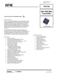
the CD. Users familiar with hardwired packet networks may consider the 24 messagebytes per packet limit quite small. Packets sent by low-power wireless systems are keptdeliberately short to improve performance where on-channel burst interference and lowsignal-to-noise conditions are often encountered.3.4 Antenna ConsiderationsSuitable antennas are crucial to the success of a Virtual Wire® application. Here areseveral key points to consider in designing antennas for your application:• Where possible, the antenna should be placed on the outside of the product. Also,try to place the antenna on the top of the product. If the product is “body worn”, try toget the antenna away for the body as far as practical.• Regulatory agencies prefer antennas that are permanently fixed to the product.Antennas can be supplied with a cable, provided a non-standard connector is usedto discourage antenna substitution (these connectors are often referred to as“Part 15” connectors).• An antenna can not be placed inside a metal case, as the case will shield it. Also,some plastics (and coatings) significantly attenuate <strong>RF</strong> signals and these materialsshould not be used for product cases where the antenna is inside the case.• The antenna designs used in the kit are included in the Drawings section of themanual. Many other antenna designs are possible, but efficient antennadevelopment requires access to antenna test equipment such as a vector networkanalyzer, calibrated test antenna, antenna range, etc. Unless you have access tothis type of equipment, consider using a standardized antenna design or antennadesign consultant. Contact <strong>RF</strong>M’s applications engineering group for additionalinformation.• A patch or slot antenna can be used in some applications where an externalantenna would be subject to damage. These types of antennas usually have to bedesigned on a case-by-case basis.14Copyright 2002 <strong>RF</strong>M®
3.5 Internal Noise Management<strong>RF</strong> transceivers operating under FCC Part 15 and similar regulations are sensitive tonoise at their operating frequency, because the desired signals must be transmitted at lowpower levels. Commonly encountered internal noise sources are microprocessors (bothfor control functions and computer functions), brush-type motors and high-speed logiccircuits. If the rise time and fall time of the clocking pulses in a microprocessor are fastenough to produce harmonics in the frequency range of the receiver and the harmonicsactually fall within the passband of the receiver, then special care must be taken toreduce the level of the harmonic at the antenna port of the receiver. It is best to choose adifferent microprocessor crystal frequency to avoid this problem. If the engineer has theoption, he should choose a microprocessor that has the slowest rise and fall time he canuse for the application to avoid the troublesome harmonics in the UHF band. If possible,brush-type motors should be avoided, since arcing of the brushes on the commutatormakes a very effective spark-gap transmitter. If it is necessary to use a brush-type motor,spark suppression techniques should be used. Such motors can be purchased with sparksuppression built-in. If the motor does not have built-in spark suppression, bypasscapacitors, series resistors and shielding may have to be employed. High-speed logiccircuits produce noise similar to microprocessors. Once again, the engineer should uselogic with the slowest rise and fall times that will work for his application.The items listed below should be considered for an application that has one or more ofthe above noise sources included:• Locate the <strong>RF</strong> transceiver and its antenna as far from the noise source as possible.• If the transceiver must be enclosed with the noise source, remotely locate the antennausing a coaxial cable.• Terminate high-speed logic circuits with their characteristic impedance and usemicrostrip interconnect lines designed for that impedance.• Keep PCB traces and wires that carry high-speed logic signals or supply brush-typemotors as short as possible. Such lines act as antennas that radiate the unwantednoise.15Copyright 2002 <strong>RF</strong>M®
• If possible, enclose the noise source in a grounded metal box and use <strong>RF</strong> decouplingon the input/output lines.• Avoid using the same power lines for the <strong>RF</strong> transceiver and the noise source or atleast thoroughly filter (<strong>RF</strong> decouple) such power lines. It is advisable to use separatevoltage regulators.• If the antenna cannot be remotely located, place it as far from the noise source aspossible (on the opposite end of the printed circuit board). Orient the antenna suchthat its axis is in the same plane with the printed circuit board containing the noisesource. Do not run wires that supply the noise source in close proximity to theantenna.3.6 Final Product TestingAny wireless data communications system must be thoroughly tested due to the“anything can happen in any sequence” nature of wireless communications. It is highlyrecommended that beta sites be chosen for operational system testing which representthe “limit” situations the system can be expected to operate in.Testing for regulatory certification is discussed in Section 3.7. It is recommended thatthe user either establish an <strong>RF</strong> test range or a working relationship with a recognizedtest lab early in the system development phase, to allow for periodic evaluation of thesystem’s emissions during development. Many labs are experienced in solving radiationproblems that cause certification test failures and/or jamming of the low-power wirelesslink. Identifying these types of problems early can save a lot of development time.16Copyright 2002 <strong>RF</strong>M®
3.7 Regulatory CertificationRegulatory Authority - Worldwide, man-made electromagnetic emissions are controlledby international treaty and the ITU (International Telecommunications Union) committeerecommendations. These treaties require countries within a geographical region to usecomparable tables for channel allocations and emission limits, to assure that all userscan operate with reasonable levels of interference.Recognizing a need to protect their limited frequency resources, many countries haveadditional local laws, regulations and government decrees for acceptable emissionlevels from various electronic equipment, both military and commercial. By requiringthat each model of equipment be tested and an authorization permit issued, agovernment works to control the sale of problematical equipment and also has record ofthe known manufacturers.Enforcement and expectation of the local law varies, of course. USA, Canada, andmost European countries have adopted ITU tables for their respective radio regions.Australia, Hong Kong and Japan also have extensive rules and regulations for lowpower transmitters and receivers, but with significant differences in the tables for thatradio region. Most other countries have less formal regulations, often modeled on eitherUSA or EU regulations.In any country, it is important to contact the Ministry of Telecommunications or PostalServices to determine any local limitations, allocations, or certifications PRIOR toassembling or testing your first product.These laws and requirements are applicable to the finished product, in the configurationthat it will be sold the general public or the end user. OEM components often can not becertified, since they require additional non-standard attachments before they have anyfunctional purpose.17Copyright 2002 <strong>RF</strong>M®
Unless otherwise marked, <strong>RF</strong>M Virtual Wire® Development Kit modules have not beencertified to any particular set of regulations. Each module has suggested countries foruse, depending on current allocations and technical limits. Emissions from receiverscan be an unexpected problem, and the <strong>RF</strong>M modules have special features to helpwith this part of the emission testing.Product Certification - General requirements for emissions and ingressions ( calledsusceptibility) are controlled by engineering standards of performance, regulations, andthe customer’s expectations.In USA and Canada, for example, you must formally measure the emissions, file for acertification or authorization, and affix a permanent marking label to every device, priorto offering your system for retail sale. Regulations allow you to build a small number fortesting and in-company use before certification and marketing. Trade shows andproduct announcements can be a problem for marketing, when the products areadvertised without proper disclaimers. With Internet access, go to “www.fcc.org” forUSA information or “www.ic.gc.ca” for Canada. The Canada rules are RCC-210,Revision 2. FCC CFR 47, Parts 2 and 15, contains the needed information for USAsales.European Union (EU) requirements allow self-certification of some systems and requireformal measurement reports for other systems. In all cases, however, the directivesdemand the “CE mark” be added to all compliant devices before any device is freelyshipped in commerce. In the EU, the EMC Directive also adds various tests andexpectations for levels of signal that will permit acceptable operation.Certification Testing - The emissions are measured in a calibrated environment definedby the regulations. USA and Canada use an “open field” range with 3 meters betweenthe device under test (DUT) and the antenna. The range is calibrated by measurementof known signal sources to generate range attenuation (correction) curves inaccordance with ANSI C63.4-1992.18Copyright 2002 <strong>RF</strong>M®
EU measurement rules are based on a similar arrangement, but a “standard dipole”antenna is substituted for the DUT to calibrate the range attenuation. Since the EUmeasurements are comparison or substitution rules, they are often easier to follow forinformal pre-testing by the designer. ETSI EN 300 220-1 has drawings that describe atypical test configuration.The United States and Canadian requirements are contained in ANSI C63.4-1992,including a step-by-step test calibration and measurement procedure. Since these rulesinclude range attenuation factors, one must make twice the measurements of the EUtest method. Other countries follow one of these two techniques, with exception for a 10meter range (separation) measurement or a different range of test frequencies. Each ofthe listed contacts will have resources to provide current regulations and certificationforms. They also can suggest sources for your formal tests, either commercial labs orthe government testing office. Unless you want to invest in a qualified radiated signalstest range, the commercial labs can help you with preliminary measurements and someexpertise in correcting any difficulties that are noted.Contacts for further information and current test facilities listings:ANSIInstitute of Electrical & Electronics Engineers,345 East 47th Street, New York, NY 10017 USAETSIEuropean Telecommunications Standard InstituteF-06921 Sophia Antipolis Cedex FRANCEFCCFederal Communications CommissionWashington DC 20554 USACanada DOCIndustrie CanadaAttn: Certification, Engineering and Operations Section,1241 Clyde Avenue, Ottawa K1A 0C8 CANADAUNITED KINGDOMLPRA (manufacturing association information)Low Power Radio Association19Copyright 2002 <strong>RF</strong>M®
The Old Vicarage, Haley Hill, Halifax HX3 6DR UKorRadiocommunications Agency (official)Waterloo Bridge House, Waterloo RoadLondon SE1 8UAJATEJapan Approvals Institute (JATE)Isomura Bldg, 1-1-3 ToranomonMinato-ku Tokyo JAPAN4 Virtual Wire® Development Kit Installation and Operation4.1 Development Kit Assembly InstructionsKit assembly includes the following steps:• Install the antennas on the data radio boards• Obtain and install AAA batteries in the protocol boards (power switch OFF)• Plug the data radio boards onto the protocol boards• Install a jumper on ID0 of one of the protocol board (Autosend) to test the VirtualWire® communication link by itself• Remove ID0 jumper and connect 9-Pin PC cables between the protocol boards andthe host computers• Install the host program on the computers• Configure the host programs and retest the Virtual Wire® communications link usingthe host computersTake care in plugging a transceiver board into a protocol board. The transceiver boardmust be oriented so that THE BOARD RESTS ON THE NYLON SCREW SUPPORTSAND NOT OVER THE BATTERIES. Be sure that the transceiver board pins arecorrectly plugged into the protocol board connector. It is possible to plug the transceiverboard in so that a pin is hanging out on the left or right. BE SURE TO INSPECT THECONNECTOR ALIGNMENT BEFORE APPLYING POWER. Options and adjustmentsare discussed below:20Copyright 2002 <strong>RF</strong>M®
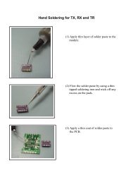
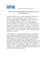
4.2 Data Radio BoardsThe <strong>DR1300A</strong> Data Radio board is configured to operate at a data rate of 2000 bps ona frequency of 433.92 MHz. The kit is shipped with a pair of Data Radio boards andmatching antennas. Data Radio boards with antennas can be purchased separately fordevelopment of applications.Antenna Options- The antennas supplied with the kit can be soldered into the antenna“eyelets” on the Data Radio PCBs. Straighten out the “L” bend at the bottom of theantennas before installing (see the Drawings section of the manual). These antennas aresimple center-loaded monopoles. Alternatively, a 50 ohm coaxial cable (RG-178, etc.) canbe soldered to the <strong>RF</strong> antenna eyelet (coax center conductor) and the adjacent groundeyelet (coax shield), if a remotely located antenna is used. The remote antenna shouldhave and impedance of approximately 50 ohms, preferably with a VSWR of less than 2:1.A remote antenna is necessary if the transceiver is housed inside a metal box, which isvery desirable if a noise source such as a high-speed microprocessor, high-speed logic ora brush-type motor is mounted in close proximity to the transceiver board itself.4.3 Protocol BoardProgramming – When using the <strong>DK</strong>200A protocol software (<strong>RF</strong>M part numberSW0012.V01) provided with the “A” series kits, there are two options that can beprogrammed on the protocol board. Placing a jumper on ID0 of one protocol boardactivates the built-in Autosend mode. This allows the kit to be tested without having tohook the protocol boards to host PCs (useful for site range testing). Placing a jumper onID3 of one board strips the packet framing and header characters off the packets itreceives. This can be handy for driving small serial printers, etc.Power Supply - Each node can be operated from three 1.5 V AAA batteries.21Copyright 2002 <strong>RF</strong>M®
RS232 Interface - Level conversion from CMOS to RS232 levels is provided by theMAX 218 IC. It is possible to remove this IC and jumper socket Pin 7 to 14 and Pin 9 to12 for direct CMOS operation.LED Functions - Three LED indicators are provided on the protocol board. With thesupplied protocol software, the LED labeled RXI indicates a valid packet start symbolhas been detected. The LED <strong>RF</strong> RCV indicates that a valid <strong>RF</strong> packet has beenreceived (no errors detected by the FCS). The LED PC RCV indicates that a messageis being sent/received from the host PC.4.4 Host Program InstallationThe supplied Windows host terminal programs(s) are installed using Windows Explorer.Go to the Windows Host Software folder on the CD and then to the V110T30C Installfolder and click on SETUP.EXE. As the install program runs, you will be asked for afolder name to store the host program files and a Start/Programs menu name (“VirtualWire” suggested). Check the Kit CD and <strong>RF</strong>M’s web site www.rfm.com foradditional/future Software.5 Theory of Operation5.1 Data Radio BoardsI/O Interface- Referring to the Data Radio Board schematic diagram, connector P1 is theinterface connector to the protocol board. Pin 1 is the transmitter data input and can bedriven directly by a CMOS gate. The transmitter is pulse ON-OFF modulated by a signalon this line changing from 0 to 3 volts. A high level turns the transmitter on and a low levelturns it off. The input impedance to this line is approximately 8.2 kilohms. Pin 2 is a Vccline for the TR3000 ASH transceiver.22Copyright 2002 <strong>RF</strong>M®
Pin 3 is the PTT line that enables the transmit mode. This line puts the TR3000 in thetransmit mode when it is high (2.5 volts minimum at 2.0 mA maximum). Pin 4 is a Vcc lineconnected in parallel with Pin 2. Pin 5 is ground. Pin 6 is unused. Pin 7 is a Vcc line,connected in parallel with Pin 2 and Pin 4. Pin 8 the data output pin from the transceiver.This data output is CMOS compatible and is capable of driving a single CMOS gate or abipolar transistor with a 510 K base resistor. The last connection to the data radio board isthe 50 ohm antenna input. The antenna can either be connected directly to the board orconnected remotely by using a 50 ohm coaxial cable.TR3000 ASH Transceiver - The heart of the <strong>DR1300A</strong> Data Radio board is the TR3000ASH transceiver. This miniature ceramic-metal hybrid provides 2-way <strong>RF</strong> communicationof data. The following section provides an introduction to the ASH transceiver’s features,capabilities, theory of operation and configurability. Additional information can be foundon the CD.ASH Transceiver Features• Designed for short-range wireless data communications• Supports <strong>RF</strong> data rates up to 115.2 kbps• 3 Vdc , low current operation with integrated power down function• Stable, easy to use, with all critical <strong>RF</strong> functions contained in the hybrid• Robust receiver performance with full sensitivity up to 1 GHz• Highly configurable with a minimum of external parts• Choice of OOK or ASK transmitter modulation• Rugged, miniature ceramic-metal package• Low implementation cost• Easy certification to FCC, ETSI and similar low-power radio regulations<strong>RF</strong>M’s amplifier-sequenced hybrid (ASH) transceivers are ideal for short-range wirelessdata communications where small size, low power consumption and low cost arerequired. All critical <strong>RF</strong> functions are contained in the hybrid, simplifying and speeding23Copyright 2002 <strong>RF</strong>M®
design-in. The receiver section is sensitive and stable. Two stages of SAW filteringprovide excellent receiver out-of-band rejection. The transmitter includes provisions foron-off keyed (OOK) or amplitude-shift keyed (ASK) modulation. The transmitteremploys SAW filtering to suppress output harmonics, facilitating compliance with FCC15.249, ETSI EN 300 220-1 and similar low-power radio regulations.ASH transceiver technology offers a rich set of enabling features in short-range wirelessapplications. Key features include:• Small size - the ASH transceiver package footprint is nominally 0.28 x 0.40 inch,with a package volume of only 0.009 in 3 (146 mm 3 ). Transceiver operation isconfigured using a dozen miniature passive components, making is practical to addshort-range wireless data connectivity to a watch, pen, PDA, etc.• Low power - the ASH transceiver operates from 3 Vdc, drawing only 6 mA averagein transmit and 1.65 to 4.5 mA in receive (set-up dependent). In addition, thetransceiver has an integrated power-down mode to support long duration operationfrom small batteries.• Robust operation - the ASH transceiver is a single-channel data radio, employingamplitude-shift keyed modulation. But unlike simple AM systems, extensiveconsideration has been given to operating robustness in the transceiverarchitecture. The receiver chain includes a narrow-band SAW filter and a SAWdelay line, which together provide excellent out-of-band rejection. The logarithmicreceiver detector features more than 70 dB of dynamic range. This can be combinedwith 30 dB of AGC (optional), providing 100 dB of overall receiver dynamic range.Data is recovered from the detected base-band signal using a compound data slicerwhich provides both excellent threshold sensitivity for low-level signals and goodrejection of interference 8-10 dB below the peak level of stronger desired signals.Operating robustness is inherent in the signal processing of the radio itself,24Copyright 2002 <strong>RF</strong>M®
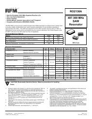
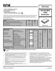
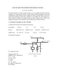
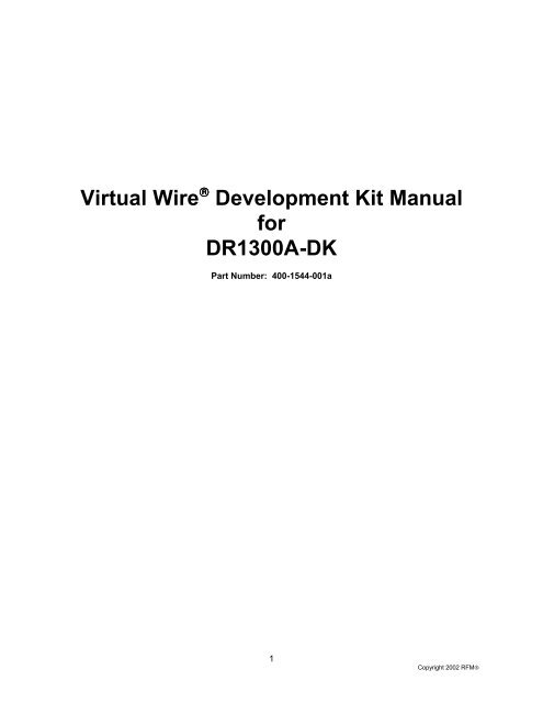
providing considerable flexibility in the choice of data protocols that can be used withthe transceiver.ASH Transceiver OperationThe ASH transceiver’s unique feature set is made possible by its system architecture.The heart of the transceiver is the amplifier-sequenced receiver section, which providesover 105 dB of stable <strong>RF</strong> and detector gain without any special shielding or decouplingprovisions. Stability is achieved by distributing the total <strong>RF</strong> gain over time. This is incontrast to a superheterodyne receiver, which achieves stability by distributing total <strong>RF</strong>gain over multiple frequencies.Refer to the Block Diagram and Timing Cycle drawing in Section A of the manual forthe following discussion. This drawing shows the basic amplifier-sequenced receiverarchitecture. Note that the bias to <strong>RF</strong> amplifiers <strong>RF</strong>A1 and <strong>RF</strong>A2 are independentlycontrolled by a pulse generator, and that the two amplifiers are coupled by a surfaceacoustic wave (SAW) delay line, which has a typical delay of 0.5 µs.An incoming <strong>RF</strong> signal is first filtered by a narrow-band SAW filter, and is then appliedto <strong>RF</strong>A1. The pulse generator turns <strong>RF</strong>A1 ON for 0.5 µs. The amplified signal from<strong>RF</strong>A1 emerges from the SAW delay line at the input to <strong>RF</strong>A2. <strong>RF</strong>A1 is now switchedOFF and <strong>RF</strong>A2 is switched ON for 0.55 µs, amplifying the <strong>RF</strong> signal further. The ONtime for <strong>RF</strong>A2 is usually set at 1.1 times the ON time for <strong>RF</strong>A1, as the filtering effect ofthe SAW delay line stretches the signal pulse from <strong>RF</strong>A1 somewhat. As shown in thetiming diagram, <strong>RF</strong>A1 and <strong>RF</strong>A2 are never on at the same time, assuring excellentreceiver stability. Note that the SAW filter and delay line act together to provide veryhigh receiver ultimate rejection.Amplifier-sequenced receiver operation has several interesting characteristics that canbe exploited in system design. The <strong>RF</strong> amplifiers in an amplifier-sequenced receivercan be turned on and off almost instantly, allowing for very quick power-down (sleep)25Copyright 2002 <strong>RF</strong>M®
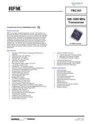
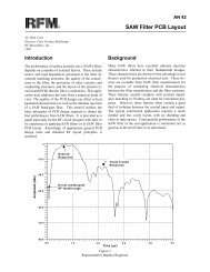
and wake-up times. Also, both <strong>RF</strong> amplifiers can be off between ON sequences totrade-off receiver noise figure for lower average current consumption. The effect onnoise figure can be modeled as if <strong>RF</strong>A1 is on continuously, with an attenuator placed infront of it with a loss equivalent to 10*log 10 (<strong>RF</strong>A1 duty factor), where the duty factor isthe average amount of time <strong>RF</strong>A1 is ON (up to 50%).Please refer to the ASH Transceiver Block Diagram in Section A for the followingdiscussion:Antenna port - the only external <strong>RF</strong> components needed for the ASH transceiver arethe antenna, antenna matching coil and electrostatic discharge (ESD) protection choke.Receiver chain - the narrow-band SAW filters provides high receiver <strong>RF</strong> selectivity. Theoutput of the SAW filter drives amplifier <strong>RF</strong>A1. This amplifier includes provisions fordetecting the onset of saturation (AGC Set), and for switching between 35 dB of gainand 5 dB of gain (Gain Select). AGC Set is an input to the AGC Control function, andGain Select is the AGC Control function output. ON/OFF control to <strong>RF</strong>A1 (and <strong>RF</strong>A2) isgenerated by the Pulse Generator & <strong>RF</strong> Amp Bias function. The output of <strong>RF</strong>A1 drivesthe low-loss SAW delay line, which has a nominal delay of 0.5 µs. Note that the SAW<strong>RF</strong> filter and SAW delay line both contribute to the excellent out-of-band rejection of thereceiver.The second amplifier, <strong>RF</strong>A2, provides 51 dB of gain below saturation. The output of<strong>RF</strong>A2 drives an active full-wave detector with 19 dB of gain. The onset of saturation ineach section of <strong>RF</strong>A2 is detected and summed to provide a logarithmic response. Thisis added to the output of the full-wave detector to produce an overall detector responsethat is linear for low signal levels, and transitions into a log response for high signallevels. This combination provides excellent threshold sensitivity and more than 70 dB ofdetector dynamic range. In combination with the 30 dB of AGC range in <strong>RF</strong>A1, morethan 100 dB of receiver dynamic range can be achieved.26Copyright 2002 <strong>RF</strong>M®
The detector output drives a three-pole, 0.05 degree equiripple low-pass filter responsewith excellent group delay flatness and minimal pulse ringing. The 3 dB bandwidth ofthe filter is adjusted with a single external resistor to match the data rate and dataencoding of the transmitted signal.The filter is followed by a base-band amplifier which boosts the detected signal to theBBOUT pin, which is coupled to the CMPIN pin or to an external data recovery process(DSP, etc.) by a series capacitor.When the transceiver is placed in power-down or in a transmit mode, the outputimpedance of BBOUT becomes very high. This feature helps preserve the charge onthe coupling capacitor to minimize data slicer stabilization time when the transceiverswitches back to the receive mode.Data Slicers - The CMPIN pin drives two data slicers, which convert the analog signalfrom BBOUT back into a data stream. The best data slicer choice depends on thesystem operating parameters. Data slicer DS1 is a capacitor-coupled comparator withprovisions for an adjustable threshold. DS1 provides the best performance at lowsignal-to-noise conditions. The threshold, or squelch, offsets the comparator’s slicinglevel, and is set with a resistor between the RREF and THLD1 pins. This thresholdallows a trade-off between receiver sensitivity and output noise density in the no-signalcondition. S2 is a “dB-below-peak” slicer. The peak detector charges rapidly to the peakvalue of each data pulse, and decays slowly in between data pulses (1:1000 ratio). Theslicer trip point can be set from 0 to 12 dB below this peak value with a resistor betweenRREF and THLD2. DS2 is best for ASK modulation where the transmitted signal hasbeen shaped to minimize signal bandwidth.AGC Control - The output of the Peak Detector also provides an AGC Reset signal tothe AGC Control function through the AGC comparator. The purpose of the AGCfunction is to extend the dynamic range of the receiver, so that two transceivers canoperate close together when running ASK and/or high data rate modulation. The AGC27Copyright 2002 <strong>RF</strong>M®
also prevents receiver saturation by a strong in-band interfering signal, allowingoperation to continue at short range in the presence of the interference. The onset ofsaturation in the output stage of <strong>RF</strong>A1 is detected and generates the AGC Set signal tothe AGC Control function. The AGC Control function then selects the 5 dB gain modefor <strong>RF</strong>A1. The AGC comparator will send a reset signal when the Peak Detector output(multiplied by 0.8) falls below the fixed reference voltage for DS1. A capacitor at theAGCCAP pin avoids AGC “chattering” during the time the signal propagates through thelog detector, low-pass filter and charges the peak detector. The AGC capacitor alsoallows the AGC hold-in time to be set longer than the peak detector decay time to avoidAGC chattering during runs of “0” bits in the received data stream. Note that AGCoperation requires the peak detector to be functioning, even if DS2 is not used. AGCoperation can be defeated by connecting the AGCCAP pin to VCC, or latched ONconnecting a resistor between the AGCCAP pin and ground.Receiver pulse generator and <strong>RF</strong> amplifier bias - The receiver amplifier-sequenceoperation is controlled by the Pulse Generator & <strong>RF</strong> Amplifier Bias module, which inturn is controlled by the PRATE and PWIDTH input pins, and the Power Down ControlSignal from the Modulation & Bias Control function.Transmitter chain - the transmitter chain consists of a SAW delay line oscillator TXA1,followed by a modulated buffer amplifier TXA2. The SAW filter suppresses transmitterharmonics to the antenna. Note that the same SAW devices used in the amplifiersequencedreceiver are reused in the transmit modes.Transmitter operation supports two modulation formats, on-off keyed (OOK)modulation, and amplitude-shift keyed (ASK) modulation. When OOK modulation ischosen, the transmitter output turns completely off between “1” data pulses. When ASKmodulation is chosen, a “1” pulse is represented by a higher transmitted power level,and a “0” is represented by a lower transmitted power level. OOK modulation providescompatibility with first-generation ASH technology, and provides for power conservation.ASK modulation must be used for high data rates (data pulses less than 30 µs). ASK28Copyright 2002 <strong>RF</strong>M®
modulation also allows the transmitted pulses to be shaped to control modulationbandwidth. The transmitter <strong>RF</strong> output voltage is proportional to the input current to theTXMOD pin, which modulates TXA2. A resistor in series with TXMOD adjusts the peaktransmitter output power.The four transceiver operating modes - receive, transmit ASK, transmit OOK andpower-down (“sleep”), are controlled by the Modulation & Bias Control function, and areselected with the CNTRL1 and CNTRL0 control pins. CNTRL1 and CNTRL0 are CMOScompatible inputs.ASH Transceiver ConfigurabilityASH transceivers are highly configurable, offering the user great flexibility in optimizingfor specific applications and protocol formats. The operating configuration is set usinglow-cost resistors and capacitors. Key points of configurability include:• Adjustable receiver sensitivity versus current consumption• Adjustable receiver low-pass filter to support various data rates/encoding techniques• Adjustable peak transmitter output power• Conventional or “dB below peak” data slicer select• Adjustable thresholds (squelch settings) for each data slicer• Adjustable AGC hold-in time and AGC latch/defeat function• OOK or ASK modulation with adjustable ASK modulation depth• Continuous or duty-cycled operation (integrated power down function)• 2.7 to 3.5 Vdc power supply range (down to 2.2 Vdc over limited temperature range)Data Radio Board Specifications<strong>DR1300A</strong> Operating Frequency 433.92 MHzModulationOn-Off Keyed29Copyright 2002 <strong>RF</strong>M®
AntennaOperating Data Rate50 ohm2000 bps (500 µs min. pulse width @ TX input)TX Frequency Toleranceless than ±200 kHz, including set-on, temperatureand aging driftTX Output Power+1 dBm nominalTX Harmonicsless than -55 dBcReceiver PerformanceBER less than 10E-4 for a -100 dBm input (2000 bps)RX Pulse Distortionless than ±10% for a 500 µs TX pulseRX Dynamic Range-100 to 0 dBmData DC Balancereceiver performance shall be maintained fordata with an average “1” density from 45 to 55%Data Run Lengthreceiver performance shall be maintained for“1” or “0” run lengths of at least 4 bitsRX Off-Channel Rejection<strong>DR1300A</strong>greater than 70 dB, 0.25 to 412 MHz and455 to 2500 MHz30Copyright 2002 <strong>RF</strong>M®
RX On-Channel Rejectionless than 30% BER degradation for an interferingsignal at least 10 dB below the desired signal after 16bits (50% duty cycle) of the desired signal receivedRX No-Signal Outputdigitized white thermal noiseDC Power Supply2.7 to 3.5 Vdc, 10 mV max peak-to-peak rippleSupply Current, RX Modeless than 4.0 mA ave @ 3 Vdc supplySupply Current, TX Modeless than 12 mA peak @ 3 Vdc supplyI/O Data Interface4.7K TX input load; RX output capableof driving one 3V CMOS gateTX/RX Control Inputlow for RX, high for TX (source 2 mA @ 2.5 V min.)Operating Temperature Range-40 to +85 deg C5.2 Protocol BoardI/O Interface - Connector J1 (see Protocol Board schematic) is the I/O interfacebetween the protocol board and the data radio board. J1-Pin 1 carries the transmit datasignal from U2-Pin 7 to the transmitter input on the Data Radio board. J1-Pin 2 providesVcc to the Data Radio board. J1-Pin 3 provides the transmit enable signal (PTT) fromPNP transistor Q2. The Data Radio board requires 2 mA at 2.5 V on the PTT input toenable the transmit mode. J1-Pin 7 is another Vcc input to the Data Radio board. J1-Pin 5 is ground. J1-Pin 4 is a third Vcc input to the Data Radio board. J1-Pin 8 carriesthe receiver digital output from the Data Radio board. Q1 provides a high inputimpedance buffer between this signal and the input to U2. J1-Pin 6 is unused in the<strong>DR1300A</strong>-<strong>DK</strong> implementation.31Copyright 2002 <strong>RF</strong>M®
RS232 Interface - Connector J2 is the RS232 interface on the protocol board. This9-Pin female connector is configured to appear as a DCE (modem). The protocol boarddoes not implement hardware flow control, so only J2-Pin 2 and J2-Pin 3 carry activesignals. J2-Pin 2 (RD) sends data to the host computer, and J2-Pin 3 receives datafrom the host computer (TD). J2 Pins 4 and 6 are connected (DTR & DSR), and J2 Pins1,7 and 8 are connected (CD, RQS, CTS) J2-Pin 5 is ground.Protocol Microcontroller - The link-layer protocol is implemented in an ATMELAT89C2051 microcontroller U2. The 8-bit microcontroller operates from an 22.118 MHzquartz crystal. The microcontroller includes 2 Kbytes of flash EPROM memory and 128bytes of RAM. The microcontroller also includes two 16-bit timers and one hardwareserial port, making it especially suitable as a link-layer packet controller.Inputs to the microcontroller include the programming pins ID0 - ID3, on Pins 14, 15, 16and 17, the buffered receive data (RRX) on Pin 6, the CMOS-level input from the hostcomputer on Pin 2. Outputs from the microcontroller include the transmit data on Pin 7,the data output to the host computer on Pin 3, the transmit enable signal Pin 19, theRS232-transceiver control on Pin 18, and the LED outputs on Pins 8 (RXI), 9 (<strong>RF</strong> RCV),and 11(PC RCV). Diode D2 and capacitor C7 form the power-up reset circuit for themicrocontroller.CMOS/RS232 Level Converter - Conversion to and from RS232 and 4.5 V CMOS logiclevels is done by U1, a Maxim MAX218 Dual RS232 Transceiver. L1, D1 and C5operate in conjunction with the IC’s switch-mode power supply to generate ±6.5 V forthe transmitter and receiver conversions. Pin 3 on the MAX218 controls the switchedmodesupply via U2 Pin 18. The RS232 serial input signal from J2-Pin 3 is input on U1-Pin 12 and is converted to a 4.5 V CMOS level (note inversion) and output on U1-Pin 9.The CMOS serial output signal from U2-Pin 2 is input on U1-Pin 7 and converted to anRS232 output (note inversion) on U1-Pin 14. This signal is found on J2-Pin 3.32Copyright 2002 <strong>RF</strong>M®
The RS232 conversion can be bypassed for direct CMOS operation by removing U1from its socket and placing one jumper in socket Pins 7 and 14 and a second jumper insocket Pins 9 and 12.Protocol Board SpecificationsHost InterfaceRS232 DCE compatible 9-Pin female(modem) connector, 19.2 kbps, byte asynchronous,1 start bit, 8 data bits, no parity, 1 stop bitRadio Interface<strong>RF</strong>M Data Radio Type-1 interface, 8-PinSIP connector, 2000 bps, 12 DC-balanced symbolbits/byte, with integrated PTT controlPower Supply4.5 Vdc nominal from 3 AAA batteriesOperating Temperature Range0 to 70 deg CStorage Temperature Range-40 to +85 deg C5.3 Protocol FirmwareDescription - The purpose of this data-link protocol is to provide automatic, verified,error-free transmission of messages between Virtual Wire® Radio Nodes via RS232serial connections to the host processors. Operation on both the RS232 side and theradio side is half-duplex.Operation of the RS232 serial connection is 19.2 kbps, with eight data bits (byte), onestop bit, and no parity bit. The transmission rate on the radio side is approximately2000 bps, using 12-bit DC-balanced symbols for each data byte. The radio receiver is33Copyright 2002 <strong>RF</strong>M®
unsquelched when not receiving data, and will output digitized white noise. The protocolis designed to tolerate continuous noise between packets for greatest sensitivity.The following I/O lines are implemented on the protocol microcontroller:radio receive line (RRX)radio transmit line (RTX)radio transmit/receive control line, high on transmit (PTT)RS232 receive line (PRX)RS232 transmit line (PTX)Maxim 218 ON/OFF control linenode ID input lines (ID0 through ID3)three LED control Lines (RXI, <strong>RF</strong> RCV and PC RCV)A description of the <strong>DK</strong>200A protocol and the source code listing is provided in the ASHTransceiver Software Designer’s Guide on the CD. Note that the <strong>DR1300A</strong> Data RadioBoards are already configured to match this protocol.34Copyright 2002 <strong>RF</strong>M®
ASH Receiver Block Diagram & Timing CycleAntennaSAWSAW Filter <strong>RF</strong>A1 <strong>RF</strong>A2Delay LineP1P2Detector &Low-PassFilterDataOutPulseGenerator<strong>RF</strong> Input<strong>RF</strong> Data PulsetPW1P1tPRItPRC<strong>RF</strong>A1 OutDelay LineOuttPW2P235Copyright 2002 <strong>RF</strong>M®
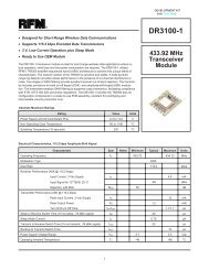
Antenna<strong>RF</strong>IOESDChoke20SAWCR FilterASH Transceiver Block DiagramTXMODTXINR TXMCNTRL1CNTRL08 17 18Modulation& Bias ControlPower DownControlVCC1: Pin 2VCC2: Pin 16GND1: Pin 1GND2: Pin 10GND3: Pin 19RREF: Pin 11CMPIN: Pin 6TXA2 TXA1LogBBOUTSAW<strong>RF</strong>A1 <strong>RF</strong>A2Delay LineLow-PassDetectorFilterBBLPFADJ95 6PKDETPeakDetectorR LPFC BBOC PKD4RefDS2dB BelowPeak ThldAGC SetGain SelectAGCDS1Ref ThldPulse Generator& <strong>RF</strong> Amp BiasAGCControlAGC ResetThresholdControlPRATE 14 15 PWIDTH AGCCAP 3THLD1 13 11 12 THLD2R PR RPWC AGCR TH1 R TH2R REFAND7RXDATA36Copyright 2002 <strong>RF</strong>M®
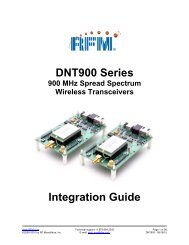
<strong>DR1300A</strong> Data Radio BoardAntenna Mounting DetailSee component placementDwg (Top View) for AntennaPad location.Mount antenna perpendicularto the Printed Circuit Boardas shown.TRTransceiverView From Antenna Port of PCB37Copyright 2002 <strong>RF</strong>M®
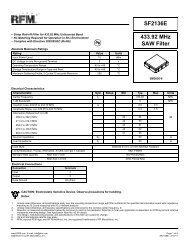
+ 3 VDCP1-2L2ANTL1C1C10+201C2PTTP1-3+ 3 VDC(U1, Pin 3)R9Q1R8C7 C4R3R1 R2C51918 17 16 15 14 13 12U12 3 4 5 6 7 8 9R7 C3 L3R5 R6C8C6C11R111110R4Data Out8Vcc7Not Used6GND5VccPTTVccData InP14321Modulation InputP1-1Data OutputP1-8Schematic, <strong>DR1300A</strong>Date: 12/18/2001, LM38Copyright 2002 <strong>RF</strong>M®
<strong>DR1300A</strong> Bill of MaterialsRef Des Qty <strong>RF</strong>M P/N DescriptionPCB1 1 400-1528-003X1 Printed Circuit BoardU1 1 TR3000 ASH Transceiver, 433.92 MHzL1 1 500-0583-100 Inductor, SMT, 56 nH, (Coilcraft 0805CS-560XJ)L2 1 500-0583-101 Inductor, SMT, 100 nH, (Coilcraft 0805CS-101XJ)Q1 1 500-0183-001 Transistor, SOT, MMBT2222LC1, C6, C9, R10 0 Not UsedC2, C4, C5, C7 4 500-0621-101 Capacitor, SMT, 100 pF, 5%, 0603C3 1 500-0621-154 Capacitor, SMT, 0.15 uF, %10, 0603C8 1 500-0621-682 Capacitor, SMT, 0.0068 uF, %10, 0603C10 1 500-0675-106 Capacitor, SMT, 10 uf, Kemet T491B106K006ASC11 1 500-0621-103 Capacitor, SMT, 0.01 uF, %10, 0603R1 1 500-0620-274 Resistor, Chip, 270K, 0.1 W, 5%, 0603R2, R6 2 500-0620-334 Resistor, Chip, 330K, 0.1 W, 5%, 0603R3, L3 2 500-0620-001 Resistor, Chip, 0.0, 0.1W, 0603R4 1 500-0828-104 Resistor, Chip, 100K, 0.1 W, 1%, 0603R5 1 500-0620-432 Resistor, Chip, 4.3K, 0.1 W, 5%, 0603R7 1 500-0620-123 Resistor, Chip, 12K, 0.1 W, 5%, 0603R8 1 500-0620-333 Resistor, Chip, 33K, 0.1 W, 5%, 0603R9 1 500-0620-273 Resistor, Chip, 27K, 0.1 W, 5%, 0603R11 1 500-0620-392 Resistor, Chip, 3.9K, 0.1 W, 5%, 0603P1 1 500-0644-001 Header, 8 Pin39Copyright 2002 <strong>RF</strong>M®
<strong>DR1300A</strong> Top Side Component Placement40Copyright 2002 <strong>RF</strong>M®
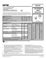
433.92 MHz Test Antenna DrawingNot drawn to scale. Units in inches.22 AWG insulated solderable magnet wire.15 turns, close wound on .100 in. dia.Finished ID = .100, +/- .003 in.Strip insulation tobare copper approx..125 min, .150 max433.92 MHz ANT.7/07/98 LAM(c) 1998 <strong>RF</strong>M400-1310-00141Copyright 2002 <strong>RF</strong>M®
2U874PB1001-2 Protocol BoardNOTES: REV ECN NO. DESCRIPTION APP/DATED3, D4, D5 are ultrabrightLED's with cathode to B+.Polarity may vary withdifferent LED's.+4.5V+4.5V+4.5V +4.5VR1R41.8K 10KL1 D1 C515uh 1N5819 1ufC7 C81uf .1ufD21N4148++D3 D4 D5C41ufJ2RTXJ1-1201 19111+Q1MMBT2222U29723AT89C2051X1 422.118MHz4 +4.5VU1MAX218812141118RRXR7510K986+75NC13C31ufP2183ID3VREF13101615PTTR610K232571846Q2ADDRESSID2+C21ufID16 5,17,20R551KID01917161514+4.5VNCNCR2154KMMBT29071210R3100K++3VC610uf+4.5V1 DATA IN (RTX)2 TX VCC3 (PTT)4 RX VCC5 GND6 (VREF)7 RX VCC8 DATA OUT (RRX)+3V+4.5VS1+1.5V+ ++C1100uf+3VJ1SCHEMATIC, Protocol Bd., 19.2KbsLee A. Mrha 5Mar99TITLE:DRAWN BY/DATE:REV SHEETDWG.NO. 444-1001-003X 1/1CODE IDENT2U874SIZEACHECKED/APPROVED<strong>RF</strong> <strong>Monolithics</strong>, <strong>Inc</strong>.DALLAS, TEXAS 7524442Copyright 2002 <strong>RF</strong>M®
PB1001-2 Protocol BoardTop Side Component Placement43Copyright 2002 <strong>RF</strong>M®
PB1001-2 Protocol BoardBottom Side Component Placement44Copyright 2002 <strong>RF</strong>M®
PB1001-2 Protcol Board Bill of MaterialsRef Des Qty <strong>RF</strong>M P/N Vendor Vendor P/N DescriptionPCB1 1 400-1354-001X1 Printed Circuit BoardC1 1 500-0669-001 Newark 51F2912 Cap, electrolytic, 100uf 25VC2, C3, C4, C5, C7, 5 500-0243-105 Newark 89F5035 Cap, SMT, Kemet T491A105K016ASC6 1 500-0244-106 Newark 92F5768 Cap, SMT, Kemet T491B106K006ASC8 1 500-0623-104 Cap, chip, 0805, 0.1uf 25VD1 1 500-0646-001 Digi-Key 1N5819CT-ND Diode, Schottky, 1N5819D2 1 500-0051-001 Digi-Key 1N4148CT-ND Diode, High speed switching, JANTX1N4148D3, D4, D5 3 500-0647-001 Digi-Key LT1034-ND T-1 Ultrabright LEDJ1 1 500-0648-001 Digi-Key WM3206-ND PCB connector, Molex 22-02-2085J2 1 500-0649-001 Newark 89N1583 PCB socket, 9 pin, SPC Technology DE9S-FRSL1 1 500-0650-001 Newark 44F4268 Inductor, 15uhP2 1 500-0651-002 Force Electronics 10-89-6084 8 pin dual row header, Molex 10-89-6084Q1 1 500-0183-001 Motorolla MMBT2222AL Transistor, SOT, MMBT2222ALQ2 1 500-0653-001 Newark MMBT2907AL Transistor, SOT, MMBT2907ALR1 1 500-0022-182 Resistor, chip, 1.8K(J), .2w, 0805R2 1 500-0732-001 Resistor, chip, 154K, .2w, 1%, 0805R3 1 500-0673-104 Resistor, chip, 100K, .2w, 1%, 0805R4 1 500-0022-204 Resistor, chip, 200K(J), .2w, 0805R5, R7 2 500-0022-513 Resistor, chip, 51K(J), .2w, 0805R6 1 500-0022-103 Resistor, chip, 10K(J), .2w, 0805S1 1 500-0724-001 Augat SSTS220PC Switch, DPDTX1 1 500-0655-002 Digi-Key CTX063-ND 22.1184 MHz Xtal, Series Resonant2 500-0656-001 Digi-Key ED3320-ND 20 pin IC socketU1 1 500-0657-001 Digi-Key MAX218CPP-ND RS232C Transceiver, MAX218CPPU2 1 500-0658-002 Arrow Electronics AT89C2051-24PC 24MHz, PDIP, commercial temperature1 500-0659-002 Keystone 2446 AAA battery holder, single cell2 500-0660-001 Digi-Key H560-ND Screw, 6-32, 1/2 inch, nylon2 500-0661-001 Digi-Key H620-ND Nut, 6-32, nylon4 500-0665-001 McMaster Carr 9723K22 Bumper feet, .375 square45Copyright 2002 <strong>RF</strong>M®