Diaphragm Pressure Gauges Stainless Steel ... - BKW Instruments
Diaphragm Pressure Gauges Stainless Steel ... - BKW Instruments
Diaphragm Pressure Gauges Stainless Steel ... - BKW Instruments

Create successful ePaper yourself
Turn your PDF publications into a flip-book with our unique Google optimized e-Paper software.
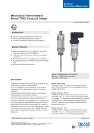
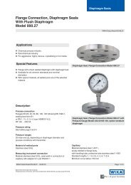
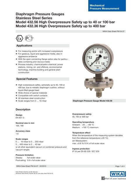
Standard versionProcess connection with lower diaphragm housing<strong>Stainless</strong> steel,G ½ B (male), 27 mm flats<strong>Pressure</strong> element≤ 0.25 bar: stainless steel> 0.25 bar: NiCrCo-alloy (Duratherm)<strong>Pressure</strong> chamber sealingFPM/FKMMovement<strong>Stainless</strong> steelDialAluminium, white, black letteringPointerAdjustable pointer, aluminium, blackCase<strong>Stainless</strong> steel, with pressure vent,gauges with liquid filling with compensating valve to ventcase(model 432.36 see Special version)Upper diaphragm housingChrome steelWindowLaminated safety glassOptions• Other process connection• Liquid filling (model 433.X6, ingress protection IP 65)• Safety pattern version (model 43X.36)• Vacuum safe to -1 bar• Medium temperature >100 °C• Admissible ambient temperature -40 ... +60 °C (siliconeoil filling)• Open connecting flanges per DIN/ASME, DN 15 toDN 80 (preferably DN 25 and 50 or DN 1" and 2" perdata sheet IN 00.10)• Wetted parts made of special materials, high overpressuresafety up to 10 bar (flange Ø 160 mm) or40 bar (flange Ø 100 mm): PTFE (model 45X.56),Hastelloy B2, Hastelloy C4, Monel, Nickel, Tantalum,Titanium(accuracy class 2.5)• Switch contacts (data sheet AC 08.01)• <strong>Pressure</strong> gauge with electrical output signal, seemodel PGT43-HP, data sheet PV 14.07• Version per ATEX Ex II 2 GD c TXSpecial versionModel 432.36 high overpressure safety up to 400 barCase with blow-out back per EN 837-3Scale ranges:0 ... 25 mbar to 0 ... 250 mbar (flange Ø 190 mm)0 ... 400 mbar to 0 ... 40 bar (flange Ø 120 mm)Flange connecting screws: steel, corrosion-protectedBezel ringCam ring (bayonet type), stainless steelPage 2 of 4WIKA Data Sheet PM 04.07 ∙ 02/2010
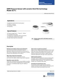
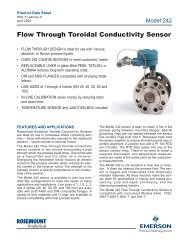
Dimensions in mmStandard version1488015.01NS Scale ranges Overpressure safe Dimensions in mm Weightin bar up to ... bar d a b D 1 D 2 e G h ± 2 SW in kg100 ≤ 0.25 40 160 15.5 49.5 101 99 17.5 G ½ B 135 27 3.4≤ 0.25 100 160 15.5 49.5 101 99 17.5 G ½ B 135 27 4.7≤ 0.25 400 190 23.5 59 101 100 17.5 G ½ B 155 27 15.7> 0.25 40 100 15.5 49.5 101 99 17.5 G ½ B 135 27 1.7> 0.25 100 100 15.5 49.5 101 99 17.5 G ½ B 135 27 1.8> 0.25 400 120 23.5 59 101 100 17.5 G ½ B 155 27 4.0160 ≤ 0.25 40 160 15.5 49.5 161 159 17.5 G ½ B 165 27 4.0≤ 0.25 100 160 15.5 49.5 161 159 17.5 G ½ B 165 27 5.3≤ 0.25 400 190 23.5 59 161 160 17.5 G ½ B 184 27 16.3> 0.25 40 100 15.5 49.5 161 159 17.5 G ½ B 165 27 2.2> 0.25 100 100 15.5 49.5 161 159 17.5 G ½ B 165 27 2.3> 0.25 400 120 23.5 59 161 160 17.5 G ½ B 184 27 4.6Process connection per EN 837-3 / 7.3WIKA Data Sheet PM 04.07 ∙ 02/2010Page 3 of 4
Ordering informationModel / Nominal size / Scale range / Connection size / Overpressure safe up to ... bar / OptionsModifications may take place and materials specified may be replaced by others without prior notice.Specifications and dimensions given in this leaflet represent the state of engineering at the time of printing.Page 4 of 4 WIKA Data Sheet PM 04.07 ∙ 02/2010WIKA Alexander Wiegand SE & Co. KGAlexander-Wiegand-Straße 3063911 Klingenberg/GermanyTel. (+49) 9372/132-0Fax (+49) 9372/132-406E-mail info@wika.dewww.wika.de02/2010 GB