Copeland 17-1268 COMPRESSION RATIO AS IT AFFECTS ...
Copeland 17-1268 COMPRESSION RATIO AS IT AFFECTS ...
Copeland 17-1268 COMPRESSION RATIO AS IT AFFECTS ...

You also want an ePaper? Increase the reach of your titles
YUMPU automatically turns print PDFs into web optimized ePapers that Google loves.
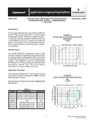
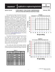
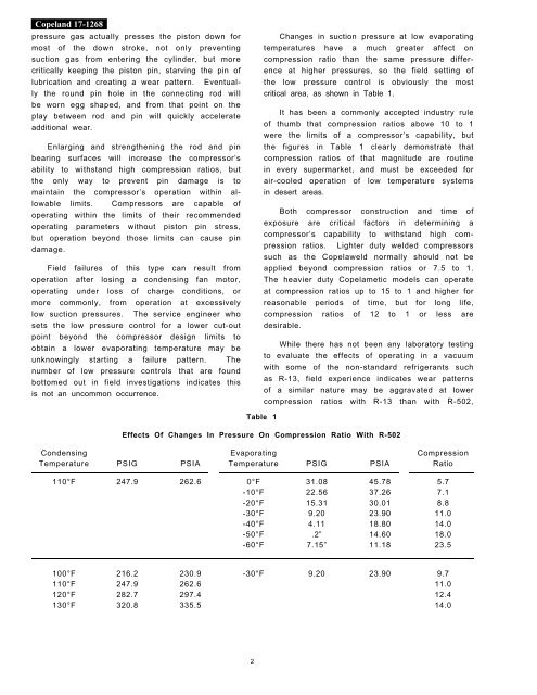
<strong>Copeland</strong> <strong>17</strong>-<strong>1268</strong>pressure gas actually presses the piston down formost of the down stroke, not only preventingsuction gas from entering the cylinder, but morecritically keeping the piston pin, starving the pin oflubrication and creating a wear pattern. Eventuallythe round pin hole in the connecting rod willbe worn egg shaped, and from that point on theplay between rod and pin will quickly accelerateadditional wear.Enlarging and strengthening the rod and pinbearing surfaces will increase the compressor’sability to withstand high compression ratios, butthe only way to prevent pin damage is tomaintain the compressor’s operation within allowablelimits. Compressors are capable ofoperating within the limits of their recommendedoperating parameters without piston pin stress,but operation beyond those limits can cause pindamage.Field failures of this type can result fromoperation after losing a condensing fan motor,operating under loss of charge conditions, ormore commonly, from operation at excessivelylow suction pressures. The service engineer whosets the low pressure control for a lower cut-outpoint beyond the compressor design limits toobtain a lower evaporating temperature may beunknowingly starting a failure pattern. Thenumber of low pressure controls that are foundbottomed out in field investigations indicates thisis not an uncommon occurrence.Changes in suction pressure at low evaporatingtemperatures have a much greater affect oncompression ratio than the same pressure differenceat higher pressures, so the field setting ofthe low pressure control is obviously the mostcritical area, as shown in Table 1.It has been a commonly accepted industry ruleof thumb that compression ratios above 10 to 1were the limits of a compressor’s capability, butthe figures in Table 1 clearly demonstrate thatcompression ratios of that magnitude are routinein every supermarket, and must be exceeded forair-cooled operation of low temperature systemsin desert areas.Both compressor construction and time ofexposure are critical factors in determining acompressor’s capability to withstand high compressionratios. Lighter duty welded compressorssuch as the Copelaweld normally should not beapplied beyond compression ratios or 7.5 to 1.The heavier duty Copelametic models can operateat compression ratios up to 15 to 1 and higher forreasonable periods of time, but for long life,compression ratios of 12 to 1 or less aredesirable.While there has not been any laboratory testingto evaluate the effects of operating in a vacuumwith some of the non-standard refrigerants suchas R-13, field experience indicates wear patternsof a similar nature may be aggravated at lowercompression ratios with R-13 than with R-502,Table 1Effects Of Changes In Pressure On Compression Ratio With R-502Condensing Evaporating CompressionTemperature PSIG PSIA Temperature PSIG PSIA Ratio110°F 247.9 262.6 0°F 31.08 45.78 5.7-10°F 22.56 37.26 7.1-20°F 15.31 30.01 8.8-30°F 9.20 23.90 11.0-40°F 4.11 18.80 14.0-50°F .2” 14.60 18.0-60°F 7.15” 11.18 23.5100°F 216.2 230.9 -30°F 9.20 23.90 9.7110°F 247.9 262.6 11.0120°F 282.7 297.4 12.4130°F 320.8 335.5 14.02