UHF-RW-G2-232 - RFID Shop
UHF-RW-G2-232 - RFID Shop
UHF-RW-G2-232 - RFID Shop

You also want an ePaper? Increase the reach of your titles
YUMPU automatically turns print PDFs into web optimized ePapers that Google loves.
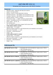
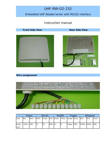
<strong>UHF</strong>-<strong>RW</strong>-<strong>G2</strong>-<strong>232</strong>Embedded <strong>UHF</strong> Reader/writer with RS<strong>232</strong> interfaceInstruction manualFront Side ViewRear Side ViewWire assignmentPower RS<strong>232</strong> RS485 Trigger WiegandColor Red Black White Purple Gray Brown Yellow orange Green Blue Pink GreenAssign-ment+9Vdc GND TX RX GND A+ B- Trigger GND DATA0 DATA1 GND
RS<strong>232</strong>- is used to communicate with PCRS<strong>232</strong> format : 8 data bits, 1 start bit , 1 stop bit , none-parity bitBaud rate : 9600,19200,38400,57600 and 115200RS485 (optional)RS485 interface – optional interfaceWiegandSupport Wiegand 26 or wiegand 34.Wiegand26 formatP0 12 bits 12 bits P1PO - even parity for first 12 bits, P1 - odd parity for second 12 bitsWiegand 34 formatP0 16 bits 16 bits P1PO - even parity for first 16 bits, P1 - odd parity for second 16 bitsTag operation – ISO18000-6B• multi-tag identification :search all the tags in the reading range to read the 8 byte UID• multi-tag reading:search all the tag in the reading range to read the 8byte data from thebeginning of the defined address• single tag writing:write one byte data on the defined tag’s address• single tag Lock:lock up the data on the defined address to prevent over-written• Query Single tag locking :Query the locking state of the defined address.Tag Operation - EPC GEN2 (ISO18000-6C)• multi-tag identification: search all the tags in the reading range to read the EPCdata (96 bits)• Single tag initialization: Initial the EPC data length of the tag (normally 96 bits)(For a new EPC <strong>G2</strong> tag, it must be initialized and pre-programmed to be read.)• Single tag writing: read the EPC data of the tag, 16 bits for each time.• Single tag locking: lock the EPC data of the tag to prevent data over-written.
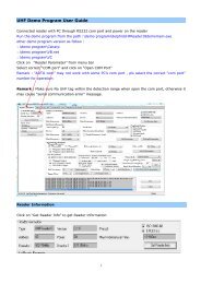
Reader Parameter Configuration[1] Connected the reader with PC through RS<strong>232</strong> .[2] Run config program from path:\\CONFIG\config.exe[3] select the com port setting and click on “Connect”CONFIG MENUWork modeCOMMAND read: reader works under the control of PC or other controller through RS<strong>232</strong>TIMING read : read Tag in interval time TIME INTERVAL : (10 ,50,100,200,500,1000)msTRIGGER READ : Trigger pin pull low to enable the reader for operation within the triggerread time
COMM SettingCom port : support com 1- com 9Reader Addr : valid address from 1 to 240 , Default is suitable for single readerBaud Rate : 9600,115200,19200,384000,576000connect : click on to connect the reader with PC for communicationReader address re-setselect a new address then click on the “set” button.The new address will be effective after reader resetRF SETTING - set the power & frequencyPower : (0-30dbm)Freq. : China (920-925Mhz): America (902-928Mhz): Europe / unknown – can customizeAntenna settingAntenna selection is suitable for the multi-antenna model onlyRead indicatorUser define - Buzzer and LED ON/OFF when tag is detected
Output port SettingRS485 – optionalCommon – can be customizeSyris – refer to syris controller 485 protocolThree Mode data transfer – Active / Passive / Response / baud rate : 9600When using Syris controller, select passive mode & 19200 bpsWiegand interfaceSupport wiegand 26 bit & wiegand 34 bitsWiegand setting : Output Num : no. of the data output / Pulse width / pulse periodsConfiguration CompletedClick on “SET” after completed the configuration.Then click on “Reset” to active the new configuration.
Demo Program InstructionRun path:\\COM DEMO\demo.exe (MR915ApiV10.dll need in the same directory)Select correct COM port , baud rate & address .Click on “connect” to establish connection with the reader.Below screen will be shown if the connection is successfully.Read EPC <strong>G2</strong> TagTimes : default “Continuous read” or (1,10,100,1000,10000)Interval : default “10ms” - set interval time to read Tag (10,50,100,500,1000)msIdentify : Read the initialized EPC Tag data and show on message windows(If the EPC Tag is not initialized , the data will be shown on message windows)Stop : stop identifyAccess parameterMemBank : EPC/TID/USER memory (pls refer to NXP EPC <strong>G2</strong> datasheet in detail)WprdPtr : define start word to read/write (0-7)WordCnt : define number of the word to read/write (1-8)Data(Hex) : input Hex dataRead : read data according to the access parameterWrite : write data according to the access parameterLock : Lock data according to the access parameterInit : to initial a new Blank EPC <strong>G2</strong> tag
Instruction to Initial a New EPC <strong>G2</strong> TagFor a new EPC <strong>G2</strong> tag , it must be initialized and pre-programmed to be read .[1] connected the reader with PC through RS<strong>232</strong>[2] click on “connect” to make sure the communication is successfully[3] then place the new EPC TAG in front of the reader and will hear “beep” sound[4] click on the “Init”[5] after initialization, all the EPC data (6 word x 16 bits) will be 00 as follow .WriteAfter initialization, you need write your own data to the tag .EPC data – 96 bit (6 word x 16 bit) – Pls refer to the NXP EPC <strong>G2</strong> datasheet in detailWordPtr “0” & “1” is the factory ID , it can’t re-written.Therefore need start to write EPC data from WordPtr “2” .Below is the example to write 4 word “0123456789ABCDEF” data to the tag.Set the data as follow, put the tag in front of the reader and Click on “Write”Readclick on “Read” to read the EPC dataBelow example to read all 96bits EPC data (WordPtr “0” and WordCnt “8”)“A1 92 30 00” is the factory ID“01 23 45 67 89 AB CD EF” is 4 word data – successfully read from the tag“00 00 00 00 “ is the last two word dataRemark :Each Tag should be written with a unique (1-6) word data.After initialization and data writing , you can read the mulit-tags by “Identify” command.
Reader installationReader unitAdjustable bracketReaderReaderVertical installationHorizontal InstallationAdjust the reader to get the best detection performanceWhen measuring or testing the reader’s read range, make sure that the tag is properlyoriented to the reader antenna, and for optimum performance, be sure the operator’s fingeris not within three inches of the tag’s antenna surface.Environment Interference will affect the reading distance.