UHF-RW-MP-232-V1 - RFID Shop
UHF-RW-MP-232-V1 - RFID Shop
UHF-RW-MP-232-V1 - RFID Shop
- No tags were found...
You also want an ePaper? Increase the reach of your titles
YUMPU automatically turns print PDFs into web optimized ePapers that Google loves.
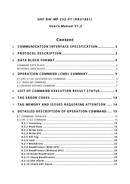
<strong>UHF</strong>-<strong>RW</strong>-<strong>MP</strong>-<strong>232</strong>-<strong>V1</strong> (RRU1861)User's Manual <strong>V1</strong>.2Content1. COMMUNICATION INTERFACE SPECIFICATION............... 32. PROTOCOL DESCRIPTION................................................ 33. DATA BLOCK FORMAT...................................................... 4COMMAND DATA BLOCK .................................................................................... 4RESPONSE DATA BLOCK .................................................................................... 44. OPERATION COMMAND (CMD) SUMMARY........................ 54.1 EPC C1 G2 (ISO18000-6C) COMMAND ........................................................... 54.2 18000-6B COMMAND................................................................................... 74.3 READER DEFINED COMMAND........................................................................ 75. LIST OF COMMAND EXECUTION RESULT STATUS............. 96. TAG ERROR CODES ........................................................ 147. TAG MEMORY AND ISSUES REQUIRING ATTENTION ..... 148. DETAILED DESCRIPTION OF OPERATION COMMAND..... 158.1 COMMAND OVERVIEV ................................................................................ 158.2 EPC C1G2 COMMAND ................................................................................ 158.2.1 Inventory ....................................................................................... 158.2.2 Read Data ...................................................................................... 168.2.3 Write Data...................................................................................... 188.2.4 Write EPC ....................................................................................... 198.2.5 Kill Tag ........................................................................................... 198.2.6 Lock ............................................................................................... 208.2.7 BlockErase ..................................................................................... 228.2.8 ReadProtect (With EPC) ................................................................. 238.2.9 ReadProtect (Without EPC) ............................................................ 248.2.10 Reset ReadProtect........................................................................ 258.2.11 Check ReadProtect ....................................................................... 258.2.12 EAS Alarm .................................................................................... 268.2.13 Check EAS Alarm .......................................................................... 27
1. COMMUNICATION INTERFACE SPECIFICATIONThe reader communicates with host (MCU, <strong>MP</strong>U, Controller) using serial communicationinterface RS<strong>232</strong> or RS485 and complete corresponding operation according to the hostcommand. The communication parameter is 57600bps 1 start bit, 8 data bits, 1 stop bitwithout parity check bit. In the process of serial communication, the least significant bit ofone byte is transmitted first and the least significant byte of command data sequence istransmitted first.2. PROTOCOL DESCRIPTIONA communication procedure is sponsored by the host sending commands and data to thereader and the reader returns the result status and data to host after command execution.Reader receives a command executes a command, only the reader complete theimplementation of a command, to receive the next command. During the implementation ofthe command in the reader, if sending commands to the reader, the command will be lost.The following table shows the process of the host computer command:HOST DIRECTION READERCommand Data BlockThe interval between two consecutive bytes in the command data block should be lessthan 15ms. During command data block sending, synchronization will lost if the host receivesany data from the reader and the host should stop command sending and restart thecommunication after 15ms.The reader completes command execution in inventory ScanTime (not including hostsending data time) except inventory command after receiving host command and returns theresults. During the period, it doesn’t process any host data. The feedback of commandexecution results is as follows:READER DIRECTION HOSTCommand Data BlockThe interval between two consecutive bytes in the response data block should be lessthan 15ms.3
3. DATA BLOCK FORMAT3.1 COMMAND DATA BLOCKLen Adr Cmd Data[] LSB-CRC16 MSB-CRC16COMMENT:LENGTH(Byte) COMMENTLen 1 Command data block length 1 byte (not includingitself). Value range is 4-96. The number of Lenequals the length of Data [] plus 4.Adr 1 Reader address, 1 byte. Value range is 0-254. Onlywill the reader conforming to the address responsethe command data block. Value 255 isbroadcasting address. All the readers will responseto the command data block with a broadcastingaddress. The default value shall be zero.Cmd 1 Operation command symbol, 1 byte.Data[] Variable Operation command parameters. There is noparameter if the LEN item equals 4.LSB-CRC16 1 CRC-16 LSB. CRC-16 checksum, 2 bytes with leastsignificant byte first.MSB-CRC16 1 CRC-16 MSB.3.2 RESPONSE DATA BLOCKLen Adr reCmd Status Data[] LSB-CRC16 MSB-CRC16COMMENT:LENGTH(Byte) COMMENTLen 1 Response data block length 1 byte (not includingitself). The number of Len equals the length ofData [] plus 5.Adr 1 Reader address, 1 byte. Value rang is 0-254.reCmd 1 Response command symbol, 1 byte. If thecommand is unrecognized, the reCmd is 0x00.Status 1 Result status value, 1byte. Refer to following tablefor details.Data[] Variable Response data. There is no this item if Len equals5.LSB-CRC16 1 CRC16 LSB .CRC-16 checksum, 2 bytes with leastsignificant byte first.4
MSB-CRC16 1 CRC16 MSBThe default value of the reader address is 0x00. The host may change it by usingreader-defined command “Write Adr”.Cyclic Redundancy Check (CRC) computation includes all data from Len. A reference CRCcomputation program is presented as follow:C-Example:#define PRESET_VALUE 0xFFFF#define POLYNOMIAL 0x8408unsigned int uiCrc16Cal(unsigned char const * pucY, unsigned char ucX){unsigned char ucI,ucJ;unsigned short int uiCrcValue = PRESET_VALUE;}for(ucI = 0; ucI < ucX; ucI++){uiCrcValue = uiCrcValue ^ *(pucY + ucI);for(ucJ = 0; ucJ < 8; ucJ++){if(uiCrcValue & 0x0001){uiCrcValue = (uiCrcValue >> 1) ^ POLYNOMIAL;}else{uiCrcValue = (uiCrcValue >> 1);}}}return uiCrcValue;4. OPERATION COMMAND (CMD) SUMMARY4.1 EPC C1 G2 (ISO18000-6C) COMMANDNUM COMMAND CODE COMMENT1 Inventory 0x01The function is used to inventory tags in theeffective field and get their EPC values.2 Read Data 0x02The function is used to read part or all of a Tag’sPassword, EPC, TID, or User memory. To the wordas a unit, start to read data from the designatedaddress.5
3 Write Data 0x034 Write EPC 0x045 Kill Tag 0x056 Lock 0x067 Block Erase 0x078 ReadProtect 0x089Read Protect(without EPC)0x0910 Reset ReadProtect 0x0a11CheckReadProtect0x0b12 EAS Alarm 0x0c13CheckEAS Alarm0x0dThe function is used to write several words in aTag’s Reserved, EPC, TID, or User memory.The function is used to write EPC value in a Tag’sEPC memory. Random write one tag in the effectivefield.The function is used to kill tag. After the tag killed,it never process command.The function is used to set Password area asreadable and writeable from any state, readableand writeable from the secured state, permanentlyreadable and writeable, never readable andwriteable. It used to set EPC, TID or User aswriteable from any state, writeable from thesecured state, permanently writeable, neverwriteable.The function is used to erase multiple words in aTag’s Password, EPC, TID, or User memory.The function is used to set designated tag readprotection. After the tag protected, it never processcommand. Even if inventory tag, reader can not getthe EPC number. The read protection can beremoved by executing Reset ReadProtect. OnlyNXP's UCODE EPC G2X tags valid.The function is used to random set one tag readprotection in the effective field. The tag must behaving the same access password. Only NXP'sUCODE EPC G2X tags valid.The function is used to remove only one tag readprotection in the effective field. The tag must behaving the same access password. Only NXP'sUCODE EPC G2X tags valid.The function is used to check only one tag in theeffective field, whether the tag is protected. It cannot check the tag whether the tag supportprotection setting. Only NXP's UCODE EPC G2X tagsvalid.The function is used to set or reset the EAS statusbit of designated tag. Only NXP's UCODE EPC G2Xtags valid.The function is used to check EAS status bit of anytag in the effective field. Only NXP's UCODE EPCG2X tags valid.6
14 Block Lock 0x0eThe function is used to permanently lock thedesignated data in designated tag’s user memory.The locked data can be read only, but not writtenand not erased. Only NXP's UCODE EPC G2X tagsvalid.4.2 18000-6B COMMANDNUM COMMAND CODE CONNECTThe function is used to Inventory only one tag in1Inventory signalthe effective field and get their ID values. If more0x506Bthan one tag in the effective field at the same time,reader may be get nothing.2The function is used to according to the givenInventory multiple0x51 conditions Inventory tags in the effective field and6Bget their ID values.3 Read Data 6B 0x52The function is used to start to read several bytesfrom the designated address.4 Write Data 6B 0x53The function is used to start to write several bytesfrom the designated address.5 Check Lock 6B 0x54The function is used to check whether thedesignated byte is locked.6 Lock 6B 0x55 The function is used to lock the designated byte.4.3 READER DEFINED COMMANDNUM COMMAND CODE CONNECTThis function is used to get reader-related1GetReaderinformation such as reader address (Adr), firmware0x21Informationversion, supported protocol type, InventoryScanTime, power and frequency.2 Set Region 0x22Sets the current region. The function is used to setthe reader working of the lower limit and the upperlimit of frequency.3 Set Address 0x24This function is used to set a new address of thereader. The address value will store in reader’sinner nonvolatile memory. Default address value is0x00. The value range is 0x00-0xFE. The address0xFF is reserved as the broadcasting address.When user tries to write a 0xFF to Adr, the readerwill set the value to 0x00 automatically.7
This function is used to set a new value to InventoryScanTime of an appointed reader. The range is4 Set ScanTime 0x25 3-255 corresponding to 3*100ms-255*100msInventory ScanTime. The default value of InventoryScanTime is 10*100ms.5 Set Baud Rate 0x28The function is used to change the serial port baudrate.6 Set Power 0x2F The function is used to set the power of reader.7Acousto-opticControl0x33 Acousto-optic Control8 Set Wiegand 0x34 The function is used to set Wiegand parameter.9 Set WorkMode 0x35 The function is used to set work mode parameter.10 Get WorkMode 0x36 The function is used to get work mode parameter.8
5. LIST OF COMMAND EXECUTION RESULT STATUSLenLengthofData[]+5LengthofData[]+5LengthofData[]+5LengthofData[]+5RESPONSE DATA BLOCKAdrSTATESreCm Statu Data[CRC16d s ]0xXX 0xXX 0x00 …….. LSB+MSB SuccessReturn0xXX 0x01 0x01 …….. LSB+MSBbeforeInventoryfinishedthe0xXX 0x01 0x02 …….. LSB+MSBInventoryscan-timeoverflow0xXX 0x01 0x03 …….. LSB+MSB More DataCONNECTReturn status 0x00 tohost after commandisexecutedsuccessfully. Datablock contains resultdata.Return status 0x01 tohost when the readerexecutesanInventory commandand gets somecomplete G2 tags’EPCbeforeuser-definedInventory-ScanTimefinished.Return status 0x02when the readerexecutesanInventory commandand does not get allG2 tags’ EPC beforeuser-definedInventory-ScanTimeoverflows.Return status 0x03when the readerexecutesanInventory commandand gets many G2tags’ EPC, Data cannot be completedwithin in a message,and then send inmultiple.9
5 0xXX 0x0a 0x0e __ LSB+MSB5 0xXX 0x53 0x10 __ LSB+MSB5 0xXX 0x55 0x11 __ LSB+MSB5 0xXX 0x55 0x12 __ LSB+MSB5 0xXX 0xXX 0x13 __ LSB+MSB5 0xXX 0xXX 0x14 __ LSB+MSBLengthofData[]0xXX 0x51 0X15 …….. LSB+MSB+5LengthofData[]0xXX 0x51 0x16 …….. LSB+MSB+5Tag isunprotected, no needto reset itThere issomelockedbytes,write failcan notlock itBe locked,cannot lockit againSave Fail,Can UseBeforePowerCannotadjustReturnbeforeInventoryfinishedInventory-Scan-TimeoverflowReturn status 0x0ewhen the NXPUCODE EPC G2X Tagis unprotected or thetag does not supportthe command.Return status 0x10when the 6B Tag iswritten data, whilethere are some lockedbytes, write fail.Return status 0x11when the 6B Tagcan’t be locked.Return status 0x12when the 6B Tag hasbeen locked.Return status 0x13when the parameteris save fail.Return status 0x14when the power cannot be adjusted.Return status 0x15 tohost when the readerexecutesanInventory commandand gets somecomplete 6B tags’UIDbeforeuser-definedInventory-ScanTimefinished.Return status 0x16when the readerexecutesanInventory commandand does not get all6B tags’ UID beforeuser-definedInventory-ScanTimeoverflows.11
LengthofData[]+50xXX 0x51 0x17 …….. LSB+MSB More DataLengthReaderof0xXX 0x51 0x18 …….. LSB+MSB moduleData[]flash is Full+5NotSupport5 0xXX 0xXX 0x19 __ LSB+MSB CommandOr AccessPasswordCommand5 0xXX 0xXX 0xF9 __ LSB+MSB executeerrorGet Tag,Poor5 0xXX 0xXX 0xFA __ LSB+MSB Communication,Inoperable5 0xXX 0xXX 0xFB __ LSB+MSBNo TagOperableErr_coTag Return6 0xXX 0xXX 0xFCLSB+MSBdeError CodeReturn status 0x17when the readerexecutesanInventory commandand gets many 6Btags’ UID, Data cannot be completedwithin in a message,and then send inmultiple.Return status 0x18when the readerexecutesanInventory commandand gets 6B tags’ UIDtoo much, more thanthe storage capacityof reader.Return status 0x19when the tag can’t setEAS Alarm. Theremay be the tag doesnot support thecommand, or thetag’s access passwordbe zero.Return status 0xF9when Commandexecute errorReturn status 0xFAwhen there are sometags in the effectivefield, but PoorCommunicationbetween reader andtag.Return status 0xFBwhen there is no tagin the effective field.Return status 0xFCwhen the tag returnsError Code.12
5 0xXX 0xXX 0xFD __ LSB+MSB5 0xXX 0x00 0xFE __ LSB+MSB5 0xXX 0xXX 0xFF __ LSB+MSBCommandlengthwrongIllegalcommandParameterErrorReturn status 0xFDwhen the length ofcommand operandsdoesn’t conform tothe commandrequest.Return status 0xFEwhen the command isan unrecognizedcommand or CRCerror.Return status 0xFFwhen the commandparameter isinvalid.13
6. TAG ERROR CODESEPC C1G2 (ISO18000-6C) Tag error codes:Error-CodeError-CodeError-CodeSupportName0x00 Other error0x03 Memory overrunError-specific0x04 Memory locked0x0b Insufficient powerNon-specific 0x0f Non-specific errorError DescriptionCatch-all for errors not coveredby other codes.The specified memory locationdoes not exist or the EPC lengthfield is not supported by theTag.The specified memory locationis locked and/or perm lockedand is either not writeable ornot readable.The Tag has insufficient powerto perform the memory-writeoperationThe Tag does not supporterror-specific codes7. TAG MEMORY AND ISSUES REQUIRING ATTENTIONA. EPC C1G2 TAG (G2 TAG)Tag memory shall be logically separated into four distinct banks, each of which maycomprise zero or more memory words. The four storage areas:Reserved memory (password memory) shall contain the kill and and/or accesspasswords, if passwords are implemented on the Tag. The kill password shall be stored atmemory addresses 00h to 1Fh; the access password shall be stored at memory addresses20h to 3Fh.EPC memory shall contain a Stored CRC at memory addresses 00h to 0Fh, a Stored PCat addresses 10h to1Fh, a code (such as an EPC, and hereafter referred to as an EPC) that identifies the objectto which the Tag is or will be attached beginning at address 20h, and if the Tag implementsExtended Protocol Control (XPC) then either one or two XPC word(s) beginning at address210h.TID memory shall contain an 8-bit ISO/IEC 15963 allocation class identifier at memorylocations 00h to 07h. TID memory shall contain sufficient identifying information above 07hfor an Interrogator to uniquely identify the custom commands and/or optional features thata Tag supports.User memory is optional. This area of different manufacturers is different. There is no14
user area in G2 tag of Inpinj Company. There are 28 words in Philips Company.Can write protect in four distinct banks. It means this memory is never writeable or notwriteable under the non-safe state; only password area can set unreadable.B. 18000-6B TAG6B tag has a memory space, the minimum 8 bytes (byte 0- 7) is UID of the tag, and can'tbe rewritten. Following byte all can be rewritten, can be locked too, but once locking, can'trewrite and unblock again.8. DETAILED DESCRIPTION OF OPERATION COMMAND8.1 COMMAND OVERVIEVThe reader supports three kinds of command, one kind is the ISO/IEC 18000-6 protocolcommand, another kind is reader-defined command, and also one kind is the transparentcommand.If the host input of the command is an unrecognized command, such as the commanddoes not support, or CRC error in the command, then the return value is as follows:Len Adr reCmd Status CRC-160x05 0xXX 0x00 0xFE LSB MSBIf the length of command operands doesn’t conform to the command request, the returnvalue is as follows:Len Adr reCmd Status CRC-160x05 0xXX 0xXX 0xFD LSB MSBTwo kinds of command reader cannot respond:1. The reader address error.2. The command is incomplete, namely the command Len is longer than the actualcommand length.8.2 EPC C1G2 COMMAND8.2.1 InventoryThe command function is used to inventory tags in the effective field and get their EPCvalues. The reader executes an Inventory command and gets tag’s EPC before any otheroperation.The user may accord need to establish this command the first biggest running time(Inventory scan time), before the command enquires. The reader completes commandexecution in inventory ScanTime (not including host sending data time) except inventorycommand after receiving host command and returns the results.The default value is 0x0A (corresponding to 10*100ms=1s). The value range is15
0x03-0xFF (corresponding to 3*100ms-255*100ms). In various environments, the actualinventory scan time may be 0-75ms longer than the InventoryScanTime defined.If the inventory scan time establishes excessively short, possibly will inventory no tagappear in inventory scan time.Command:Len Adr Cmd Data[] CRC-160x04 0xXX 0x01 ----- LSB MSBRespond:Len Adr reCmd StatusNumData[]EPC IDCRC-160xXX 0xXX 0x01 0xXX 0xXXEPC-1, EPC-2,EPC-3…LSB MSBParameter Connect:Status Table:StatusConnect0x01 Command over, and return inventoried tag’s EPC.The reader does not get all G2 tags’ EPC before user-defined0x02 Inventory-ScanTime overflows. Command force quit, and returnsinventoried tags’ EPC.The reader executes an Inventory command and gets many G2 tags’0x03 EPC. Data can not be completed within in a message, and then send inmultiple.The reader executes an Inventory command and gets G2 tags’ EPC0x04 too much, more than the storage capacity of reader, and returnsinventoried tags’ EPC.Num: The number of tag detected.EPC ID: Inventoried tag’s EPC data, EPC-1 is the first tag EPC Len + EPC data, etc. Themost significant word (EPC C1 G2 data in word units) of EPC is transmitted first and the mostsignificant byte of word is transmitted first. EPC Len is one byte.8.2.2 Read DataThe command is used to read part or all of a Tag’s Password, EPC, TID, or User memory.To the word as a unit, start to read data from the designated address.Command:Len Adr Cmd Data[] CRC-160xXX 0xXX 0x02 ----- LSB MSBData as follows:Data[]ENumEPC Mem WordPtr Num Pwd MaskAdr MaskLen16
0xXX Variable 0xXX 0xXX 0xXX 4Byte 0xXX 0xXXParameter Connect:ENum: EPC length, in word units. The length of EPC is less than 15 words, can be 0 or 15.Otherwise, it returns the parameters error message.EPC: Be operated tag’s EPC number. EPC length according to the decision of the EPCnumber, EPC numbers in word units, and must be an integer number of lengths. High wordfirst, the high byte of each word first. Requirement given here is a complete EPC number.Mem: One byte. It specifies whether the Read accesses Password, EPC, TID, or Usermemory. 0x00: Password memory; 0x01: EPC memory; 0x02; TID memory; 0x03: Usermemory. Other values reserved. Other value when error occurred.WordPtr: One byte. It specifies the starting word address for the memory read. Forexample, WordPtr = 00h specifies the first 16-bit memory word, WordPtr = 01h specifiesthe second 16-bit memory word, etc.Num: One byte. It specifies the number of 16-bit words to be read. The value is less then120, can not be 0. Otherwise, it returns the parameters error message.Pwd: Four bytes, they are Access Password. The most significant word of AccessPassword is first, the most significant byte of word is first. The first bit of 32-bit accesspassword is left, and the last bit of 32-bit access password is right. Only done the memory setto lock and the Access Password is not zero, it needs Pwd. In other cases, Pwd can be filledwith any value, but not vacant.MaskAdr: One byte, it specifies the starting byte address for the memory mask. Forexample, MaskAdr = 0x00 specifies the first EPC bytes, MaskAdr = 0x01 specifies thesecond EPC bytes, etc.MaskLen: One byte, it is the mask length. That a Tag compares against the memorylocation that begins at MaskAdr and ends MaskLen bytes later. MaskAdr + MaskLen mustbe less the length of ECP number. Otherwise, it returns the parameters error message.Notes: That a tag compares against complete EPC number when the MaskAdr andMaskLen vacant.Respond:Len Adr reCmd Status Data[] CRC-160xXX 0xXX 0x02 0x00 Word1, Word2,… LSB MSBParameter Connect:Word1, Word2….: In word units, one word is two bytes. High byte is first. Word1is the word which reads from the start address, Word2 is the word which reads from thesecond address, etc.17
8.2.3 Write DataThe command is used to write several words in a Tag’s Reserved, EPC, TID, or Usermemory.Command:Len Adr Cmd Data[] CRC-160xXX 0xXX 0x03 ----- LSB MSBData as follows:Data[]WNumENuWordPEPC MemmtrWdt Pwd MaskAdr MaskLen0xXX 0xXX Variable 0xXX 0xXX Variable 4Byte 0xXX 0xXXParameter Connect:WNum: One byte. It specifies the number of 16-bit words to be written. The value cannot be 0. Otherwise, it returns the parameters error message.ENum: EPC length, in word units. The length of EPC is less than 15 words, can be 0 or 15.Otherwise, it returns the parameters error message.EPC: Be operated tag’s EPC number. EPC length according to the decision of the EPCnumber, EPC numbers in word units, and must be an integer number of lengths. High wordfirst, the high byte of each word first. Requirement given here is a complete EPC number.Mem: One byte. It specifies whether the Write accesses Password, EPC, TID, or Usermemory. 0x00: Password memory; 0x01: EPC memory; 0x02; TID memory; 0x03: Usermemory. Other values reserved. Other value when error occurred.WordPtr: One byte. It specifies the starting word address for the memory write. Forexample, WordPtr = 00h specifies the first 16-bit memory word, WordPtr = 01h specifiesthe second 16-bit memory word, etc.Wdt: Be written words. The most significant byte of each word is first. Wdt specifies thearray of the word to be written. For example, WordPtr equal 0x02, then the first word inData write in the address 0x02 of designated Mem, the second word write in 0x03, etc.Pwd: Four bytes, they are Access Password. The most significant word of AccessPassword is first, the most significant byte of word is first. The first bit of 32-bit accesspassword is left, and the last bit of 32-bit access password is right. Only done the memory setto lock and the Access Password is not zero, it needs Pwd. In other cases, Pwd can be filledwith any value, but not vacant.MaskAdr: One byte, it specifies the starting byte address for the memory mask. For18
example, MaskAdr = 0x00 specifies the first EPC bytes, MaskAdr = 0x01 specifies thesecond EPC bytes, etc.MaskLen: One byte, it is the mask length. That a Tag compares against the memorylocation that begins at MaskAdr and ends MaskLen bytes later. MaskAdr + MaskLen mustbe less the length of ECP number. Otherwise, it returns the parameters error message.Notes: That a tag compares against complete EPC number when the MaskAdr andMaskLen vacant.Respond:Len Adr reCmd Status Data[] CRC-160x05 0xXX 0x03 0x00 ----- LSB MSB8.2.4 Write EPCThe command is used to write EPC number in a Tag’s EPC memory. Random write one tagin the effective field.Command:Data[]Len Adr CmdCRC-16ENum Pwd WEPC0xXX 0xXX 0x04 0xXX 4Byte Variable LSB MSBParameter Connect:ENum: One byte, it specifies the array of the word to be written EPC length, in word units.The length of EPC is not more than 15 words, can’t be 0. Otherwise, it returns the parameterserror message.Pwd: Four bytes, they are Access Password. The most significant word of AccessPassword is first, the most significant byte of word is first. The first bit of 32-bit accesspassword is left, and the last bit of 32-bit access password is right. Only done the memory setto lock and the Access Password is not zero, it needs Pwd. In other cases, Pwd can be filledwith any value, but not vacant.WEPC: Be written EPC value. WEPC is not more than 15 words, can’t be 0. Otherwise, itreturns the parameters error message.Respond:Len Adr reCmd Status Data[] CRC-160x05 0xXX 0x04 0x00 ----- LSB MSB8.2.5 Kill TagThe command is used to kill tag. After the tag killed, it never process command.19
Command:Len Adr Cmd Data[] CRC-160xXX 0xXX 0x05 ----- LSB MSBData as follows:Data[]ENum EPC Killpwd MaskAdr MaskLen0xXXVariable4Byte 0xXX 0xXXParameter Connect:ENum: EPC length, in word units. The length of EPC is less than 15 words, can be 0 or 15.Otherwise, it returns the parameters error message.EPC: Be operated tag’s EPC number. EPC length according to the decision of the EPCnumber, EPC numbers in word units, and must be an integer number of lengths. High wordfirst, the high byte of each word first. Requirement given here is a complete EPC number.Killpwd: Four bytes, they are Kill Password. The most significant word of Kill Password isfirst, the most significant byte of word is first. The first bit of 32-bit Kill Password is left, andthe last bit of 32-bit Kill Password is right. Tag’s whose Kill Password is zero do not executea kill operation; if such a Tag receives a Kill command it ignores the command andbackscatters an error codeMaskAdr: One byte, it specifies the starting byte address for the memory mask. Forexample, MaskAdr = 0x00 specifies the first EPC bytes, MaskAdr = 0x01 specifies thesecond EPC bytes, etc.MaskLen: One byte, it is the mask length. That a Tag compares against the memorylocation that begins at MaskAdr and ends MaskLen bytes later. MaskAdr + MaskLen mustbe less the length of ECP number. Otherwise, it returns the parameters error message.Notes: That a tag compares against complete EPC number when the MaskAdr andMaskLen vacant.Respond:Len Adr reCmd Status Data[] CRC-160x05 0xXX 0x05 0x00 ----- LSB MSB8.2.6 LockThe Lock command Lock reversibly or permanently locks a password or an entire EPC,TID, or User memory bank in a readable/writeable or unreadable/unwriteable state.Once tag’s password memory establishes to forever may be readable and writable orunreadable and unwriteable, then later cannot change its read-write protection again. Tag’sEPC memory, TID memory or user memory, if establishes to forever may be writeable or20
unwriteable, then later cannot change its read-write protection again. If sends the commandto want forcefully to change the above several states, then the tag will return to the errorcode.When the tag’s memory established in a readable/writeable state, the command mustgive the Access Password, so tag’s Access Password is not zero.Command:Len Adr Cmd Data[] CRC-160xXX 0xXX 0x06 ----- LSB MSBData as follows:Data[]ENum EPC Select SetProtect Pwd MaskAdr MaskLen0xXX Variable 0xXX 0xXX 4Byte 0xXX 0xXXParameter Connect:ENum: EPC length, in word units. The length of EPC is less than 15 words, can be 0 or 15.Otherwise, it returns the parameters error message.EPC: Be operated tag’s EPC number. EPC length according to the decision of the EPCnumber, EPC numbers in word units, and must be an integer number of lengths. High wordfirst, the high byte of each word first. Requirement given here is a complete EPC number.Select: One byte, defined as follows:0x00: Control Kill Password protection setting.0x01: Control Access password protection setting.0x02: Control EPC memory protection setting.0x03: Control TID memory protection setting.0x04: Control User memory protection setting.Other value when error occurred.SetProtect:When Select is 0x00 or 0x01, SetProtect means as follows:0x00: readable and writeable from any state.0x01: permanently readable and writeable.0x02: readable and writeable from the secured state.0x03: never readable and writeableWhen Select is 0x02, 0x03 or 0x04, SetProtect means as follows:0x00: writeable from any state.0x01: permanently writeable.0x02: writeable from the secured state.0x03: never writeable.Other value when error occurred.Pwd: Four bytes, they are Access Password. The most significant word of Access21
Password is first, the most significant byte of word is first. The first bit of 32-bit accesspassword is left, and the last bit of 32-bit access password is right. When tag’s AccessPassword is zero, Pwd can be filled with any value, and the tag’s Access Password is not zero,Pwd must be right Access Password.MaskAdr: One byte, it specifies the starting byte address for the memory mask. Forexample, MaskAdr = 0x00 specifies the first EPC bytes, MaskAdr = 0x01 specifies thesecond EPC bytes, etc.MaskLen: One byte, it is the mask length. That a Tag compares against the memorylocation that begins at MaskAdr and ends MaskLen bytes later. MaskAdr + MaskLen mustbe less the length of ECP number. Otherwise, it returns the parameters error message.Notes: That a tag compares against complete EPC number when the MaskAdr andMaskLen vacant.Respond:Len Adr reCmd Status Data[] CRC-160x05 0xXX 0x06 0x00 ----- LSB MSB8.2.7 BlockEraseThe command is used to erase multiple words in a Tag’s Password, EPC, TID, or Usermemory.Command:Len Adr Cmd Data[] CRC-160xXX 0xXX 0x07 ----- LSB MSBData as follows:Data[]ENumEPC Mem WordPtr Num Pwd MaskAdr MaskLen0xXX Variable 0xXX 0xXX 0xXX 4Byte 0xXX 0xXXParameter Connect:ENum: EPC length, in word units. The length of EPC is less than 15 words, can be 0 or 15.Otherwise, it returns the parameters error message.EPC: Be operated tag’s EPC number. EPC length according to the decision of the EPCnumber, EPC numbers in word units, and must be an integer number of lengths. High wordfirst, the high byte of each word first. Requirement given here is a complete EPC number.Mem: One byte. It specifies whether the Erase accesses Password, EPC, TID, or Usermemory. 0x00: Password memory; 0x01: EPC memory; 0x02; TID memory; 0x03: User22
memory. Other values reserved. Other value when error occurred.WordPtr: One byte. It specifies the starting word address for the memory block erase.For example, WordPtr = 00h specifies the first 16-bit memory word, WordPtr = 01hspecifies the second 16-bit memory word, etc. WordPtr must be bigger than 0x00 when iterases EPC memory.Num: One byte. It specifies the number of 16-bit words to be erased. If Num = 0x00, itreturns the parameters error message.Pwd: Four bytes, they are Access Password. The most significant word of AccessPassword is first, the most significant byte of word is first. The first bit of 32-bit accesspassword is left, and the last bit of 32-bit access password is right. Only done the memory setto lock and the Access Password is not zero, it needs Pwd. In other cases, Pwd can be filledwith any value, but not vacant.MaskAdr: One byte, it specifies the starting byte address for the memory mask. Forexample, MaskAdr = 0x00 specifies the first EPC bytes, MaskAdr = 0x01 specifies thesecond EPC bytes, etc.MaskLen: One byte, it is the mask length. That a Tag compares against the memorylocation that begins at MaskAdr and ends MaskLen bytes later. MaskAdr + MaskLen mustbe less the length of ECP number. Otherwise, it returns the parameters error message.Notes: That a tag compares against complete EPC number when the MaskAdr andMaskLen vacant.Respond:Len Adr reCmd Status Data[] CRC-160x05 0xXX 0x07 0x00 ----- LSB MSB8.2.8 ReadProtect (With EPC)The command is used to set designated tag read protection. After the tag protected, itnever process command. Even if inventory tag, reader can not get the EPC number. The readprotection can be removed by executing Reset ReadProtect. Only NXP's UCODE EPC G2X tagsvalid.Command:Len Adr Cmd Data[] CRC-160xXX 0xXX 0x08 ----- LSB MSBData as follows:Data[]ENu EPC Pwd MaskAdr MaskLen23
m0xXX Variable 4Byte 0xXX 0xXXParameter Connect:ENum: EPC length, in word units. The length of EPC is less than 15 words, can be 0 or 15.Otherwise, it returns the parameters error message.EPC: Be operated tag’s EPC number. EPC length according to the decision of the EPCnumber, EPC numbers in word units, and must be an integer number of lengths. High wordfirst, the high byte of each word first. Requirement given here is a complete EPC number.Pwd: Four bytes, they are Access Password. The most significant word of AccessPassword is first, the most significant byte of word is first. The first bit of 32-bit accesspassword is left, and the last bit of 32-bit access password is right. Be operated tags’ AccessPassword can not be zero.MaskAdr: One byte, it specifies the starting byte address for the memory mask. Forexample, MaskAdr = 0x00 specifies the first EPC bytes, MaskAdr = 0x01 specifies thesecond EPC bytes, etc.MaskLen: One byte, it is the mask length. That a Tag compares against the memorylocation that begins at MaskAdr and ends MaskLen bytes later. MaskAdr + MaskLen mustbe less the length of ECP number. Otherwise, it returns the parameters error message.Notes: That a tag compares against complete EPC number when the MaskAdr andMaskLen vacant.Respond:Len Adr reCmd Status Data[] CRC-160x05 0xXX 0x08 0x00 ----- LSB MSB8.2.9 ReadProtect (Without EPC)The command is used to random set random one tag read protection in the effective field.The tag must be having the same access password. Only NXP's UCODE EPC G2X tags valid.Command:Data[]Len Adr CmdCRC-16Pwd0x08 0xXX 0x09 4Byte LSB MSBParameter Connect:Pwd: Four bytes, they are Access Password. The most significant word of AccessPassword is first, the most significant byte of word is first. The first bit of 32-bit accesspassword is left, and the last bit of 32-bit access password is right. Be operated tags’ AccessPassword can not be zero.24
Respond:Len Adr reCmd Status Data[] CRC-160x05 0xXX 0x09 0x00 ----- LSB MSB8.2.10 Reset ReadProtectThe command is used to remove only one tag read protection in the effective field. Thetag must be having the same access password. Only NXP's UCODE EPC G2X tags valid.Command:Data[]Len Adr CmdCRC-16Pwd0x08 0xXX 0x0a 4Byte LSB MSBParameter Connect:Pwd: Four bytes, they are Access Password. The most significant word of AccessPassword is first, the most significant byte of word is first. The first bit of 32-bit accesspassword is left, and the last bit of 32-bit access password is right. Pwd must be right tag’sAccess Password.Respond:Len Adr reCmd Status Data[] CRC-160x05 0xXX 0x0a 0x00 ----- LSB MSBNotes: If a tag does not support the command, is unlocked.8.2.11 Check ReadProtectThe command is used to check only one tag in the effective field, whether the tag isprotected. It can not check the tag whether the tag support protection setting. Only NXP'sUCODE EPC G2X tags valid.Command:Len Adr Cmd Data[] CRC-160x04 0xXX 0x0b ----- LSB MSBRespond:Len Adr reCmd Status Data[] CRC-160x06 0xXX 0x0b 0x00ReadProLSB MSBParameter Connect:ReadProConnect0x00 Tag is protected.0x01 Tag is unprotected.Notes: If a tag does not support the command, is unprotected.25
8.2.12 EAS AlarmThe function is used to set or reset the EAS status bit of designated tag. Only NXP'sUCODE EPC G2X tags valid.Command:Len Adr Cmd Data[] CRC-160xXX 0xXX 0x0c ----- LSB MSBData as follows:Data[]ENumEPC Pwd EAS MaskAdr MaskLen0xXX Variable 4Byte 0xXX 0xXX 0xXXParameter Connect:ENum: EPC length, in word units. The length of EPC is less than 15 words, can be 0 or 15.Otherwise, it returns the parameters error message.EPC: Be operated tag’s EPC number. EPC length according to the decision of the EPCnumber, EPC numbers in word units, and must be an integer number of lengths. High wordfirst, the high byte of each word first. Requirement given here is a complete EPC number.Pwd: Four bytes, they are Access Password. The most significant word of AccessPassword is first, the most significant byte of word is first. The first bit of 32-bit accesspassword is left, and the last bit of 32-bit access password is right. Be operated tags’ AccessPassword can not be zero.EAS: One byte. Bit0=0 means reset the EAS state, Bit0=1 means set the EASstate.Bit1-Bit7 default 0.MaskAdr: One byte, it specifies the starting byte address for the memory mask. Forexample, MaskAdr = 0x00 specifies the first EPC bytes, MaskAdr = 0x01 specifies thesecond EPC bytes, etc.MaskLen: One byte, it is the mask length. That a Tag compares against the memorylocation that begins at MaskAdr and ends MaskLen bytes later. MaskAdr + MaskLen mustbe less the length of ECP number. Otherwise, it returns the parameters error message.Notes: That a tag compares against complete EPC number when the MaskAdr andMaskLen vacant.Respond:Len Adr reCmd Status Data[] CRC-1626
0x05 0xXX 0x0c 0x00 ----- LSB MSB8.2.13 Check EAS AlarmThe function is used to check EAS status bit of any tag in the effective field. Only NXP'sUCODE EPC G2X tags valid.Command:Len Adr Cmd Data[] CRC-160x04 0xXX 0x0d ----- LSB MSBRespond:Len Adr reCmd Status Data[] CRC-160x05 0xXX 0x0d 0x00 ----- LSB MSBIt returns "no tag actionable" message when No EAS alarm8.2.14 User Block LockThe command is used to permanently lock the designated data in designated tag’s usermemory. Block Lock command supports an additional locking mechanism, which allowsthe locking of individual 32 bit blocks (rows) in the 224 bit User Memory. Once locked theselocks cannot be unlocked. Only NXP's UCODE EPC G2X tags valid.Command:Len Adr Cmd Data[] CRC-160xXX 0xXX 0x0e ----- LSB MSBData as follows:Data[]ENumEPC pwd WrdPointer MaskAdr MaskLen0xXX Variable 4Byte 0xXX 0xXX 0xXXParameter Connect:ENum: EPC length, in word units. The length of EPC is less than 15 words, can be 0 or 15.Otherwise, it returns the parameters error message.EPC: Be operated tag’s EPC number. EPC length according to the decision of the EPCnumber, EPC numbers in word units, and must be an integer number of lengths. High wordfirst, the high byte of each word first. Requirement given here is a complete EPC number.Pwd: Four bytes, they are Access Password. The most significant word of AccessPassword is first, the most significant byte of word is first. The first bit of 32-bit accesspassword is left, and the last bit of 32-bit access password is right. The Pwd can be filled withany value when the User memory does not be lock with Access Password, but not vacant.27
WrdPointer: Each EEPROM row can be addressed by either of the two relatedWordPointers:Either of two WordPointers can address one single User Memory rowWrdPointerUser EEPROM row0 or 1 02 or 3 14 or 5 26 or 7 38 or 9 410 or 11 512 or 13 6MaskAdr: One byte, it specifies the starting byte address for the memory mask. Forexample, MaskAdr = 0x00 specifies the first EPC bytes, MaskAdr = 0x01 specifies thesecond EPC bytes, etc.MaskLen: One byte, it is the mask length. That a Tag compares against the memorylocation that begins at MaskAdr and ends MaskLen bytes later. MaskAdr + MaskLen mustbe less the length of ECP number. Otherwise, it returns the parameters error message.Notes: That a tag compares against complete EPC number when the MaskAdr andMaskLen vacant.Respond:Len Adr reCmd Status Data[] CRC-160x05 0xXX 0x0e 0x00 ----- LSB MSB8.3 18000-6B COMMAND8.3.1Inventory Signal 6BThe command is used to Inventory only one tag in the effective field and get their IDvalues. If more than one tag in the effective field at the same time, reader may be getnothing.Command:Len Adr Cmd CRC-160x04 0xXX 0x50 LSB MSBRespond:Len Adr reCmd Status Data[] CRC-160x0d 0xXX 0x50 0x00 ID LSB MSBParameter Connect:ID: 8 bytes, it is 6B tag’s UID. The low byte is fist.28
8.3.2 Inventory Multiple 6BThe command is used to according to the given conditions Inventory tags in the effectivefield and get their ID values.Command:Data[]Len Adr CmdCRC-16Condition Address Mask Word_data0x0f 0xXX 0x51 0xXX 0xXX 0xXX 8 Bytes LSB MSBParameter Connect:Condition: The condition of detecting tags.0x00: equal condition.0x01: unequal condition.0x02: greater than condition.0x03: lower than condition.Address: The tag’s start address to compare.Mask: It pointed to the data is used to compare. Highest bit in the mask correspond withthe far-left byte in the Condition Content. The corresponding bit in the mask is 1 to comparethe bit in the Condition Content with the corresponding byte in the tag. The corresponding bitin the mask is 0, not compare.Word_data: 8 bytes. It pointed to the array is used to compare.Respond:Len Adr reCmd Status Num Data[] CRC-160xXX 0xXX 0x51 0xXX 0xXX UID1, UID2… LSB MSBParameter Connect:Status Table:StatusConnect0x15 Command over, and return inventoried tag’s UID.The reader does not get all 6B tags’ UID before user-defined0x16 Inventory-ScanTime overflows. Command force quit, and returnsinventoried tags’ UID.The reader executes an Inventory command and gets many 6B tags’0x17 UID. Data can not be completed within in a message, and then send inmultiple.The reader executes an Inventory command and gets 6B tags’ UID0x18 too much, more than the storage capacity of reader, and returnsinventoried tags’ UID.Num: The number of tag detected.Data []: UID. Each UID length is 8 bytes. The least significant byte of UID is transmittedfirst.29
8.3.3 Read Data 6BThe command is used to start to read several bytes from the designated address.Data[]Len Adr CmdCRC-16Address ID Num0x0e 0xXX 0x52 0xXX 8 Bytes 0xXX LSB MSBParameter Connect:Address: The tag’s start byte address to read. The range is 0-223. Otherwise, it returnsthe parameters error message.Num: In byte units. It specifies the number of 8-bit bytes to be read. The value range is1-32, and Address + Num must be less than 224. Otherwise, it returns the parameterserror message.ID: 8 bytes, it is 6B tag’s UID. The low byte is fist.Respond:Len Adr reCmd Status Data[] CRC-160x05 0xXX 0x52 0x00 Data LSB MSBData: It is read data, the low byte is fist.8.3.4 Write Data 6BThe command is used to start to write several bytes from the designated address.Command:Data[]Len Adr CmdCRC-16Address ID Wdata0xXX 0xXX 0x53 0xXX 8 Bytes Variable LSB MSBParameter Connect:Address: The tag’s start byte address to write. The range is 8-223. Otherwise, it returnsthe parameters error message.ID: 8 bytes, it is 6B tag’s UID. The low byte is fist.Wdata: It pointed to the array to write, range is 1-32. If Address + WriteDataLengreater than 224, or Wdata greater than 32 or is zero, reader will return parameter errormessage. The high bytes of Wdata write in the low address in tag.Respond:reCm StatuLen AdrData[] CRC-16d s0x05 0xXX 0x53 0x00 Data LSB MSB30
8.3.5 Check Lock 6BThe command is used to check whether the designated byte is locked.Command:Data[]Len Adr CmdCRC-16Address ID0x0d 0xXX 0x54 0xXX 8 Bytes LSB MSBParameter Connect:Address: The tag’s byte address to check lock. The range is 0-223. Otherwise, it returnsthe parameters error message.ID: 8 bytes, it is 6B tag’s UID. The low byte is fist.Respond:reCmLen AdrStatus Data[] CRC-16d0x06 0xXX 0x54 0x00 LockState LSB MSBLockState:0x00: Unlocked0x01: locked8.3.6 Lock 6BThe command is used to lock the designated byte.Command:Data[]Len Adr CmdCRC-16Address ID0x0d 0xXX 0x55 0xXX 8 Bytes LSB MSBParameter Connect:Address: The tag’s byte address to lock. The range is 8-223. Otherwise, it returns theparameters error message.ID: 8 bytes, it is 6B tag’s UID. The low byte is fist.Respond:Len Adr reCmd Status Data[] CRC-160x05 0xXX 0x55 0x00 ----- LSB MSB8.4 READ-DEFINED COMMAND8.4.1 Get Reader InformationThe host sends this command to get the reader’s information including reader’s address(Adr), firmware version, reader type (Type), supported protocol (Tr_Type), reader power,work frequency, and InventoryScanTime value.31
Command:Len Adr Cmd Data[] CRC-160x04 0xXX 0x21 ----- LSB MSBRespond:LenAdrreCmdStatusData[]CRC-160x0d0xXX 0x21 0x00Version, Type, Tr_Type,DMaxFre, DMinFre, Power,ScntmLSBMSBParameter Connect:Parameter Length(Byte)ConnectVersion 2The first byte is version number; the secondbyte is sub-version number.Type 1 The reader type byte. 0x09 lines on RRU1861Tr_Type 1One byte supported protocol information. Bit1 is1 for18000-6C protocol; Bit0 is 1 for 18000-6Bprotocol.Bit7-Bit6 indicates Frequency Band andDMaxFre 1 Bit5-Bit0 indicates the reader current maximumfrequency.Bit7-Bit6 indicates Frequency Band andDMinFre 1 Bit5-Bit0 indicates the reader current minimumfrequency.Power 1The output power of reader. Range is 0 to 18,when Power is 0xFF, it means the output powerof reader unknown.Scntm 1Inventory Scan Time, the value of time limit forinventory command.Frequency Band:MaxFre(Bit7) MaxFre(Bit6) MinFre(Bit7) MinFre(Bit6) FreqBand0 0 0 0 User band0 0 0 1 Chineseband20 0 1 0 US band0 0 1 1 Korean band0 1 0 0 RFU0 1 0 1 RFU… … … … …1 1 1 1 RFU32
8.4.2 Set RegionThe host sends this command to change the current region of the reader. The value isstored in the reader’s inner EEPROM and is nonvolatile after reader powered off.Command:Data[]Len Adr CmdCRC-16MaxFre MinFre0x07 0xXX 0x22 0xXX 0xXX LSB MSBParameter Connect:MaxFre: One byte, Bit7-Bit6 indicates Frequency Band and Bit5-Bit0 indicates the readercurrent maximum frequency.MinFre: One byte, Bit7-Bit6 indicates Frequency Band and Bit5-Bit0 indicates the readercurrent minimum frequency (maximum frequency >= minimum frequency).Frequency Band:MaxFre(Bit7) MaxFre(Bit6) MinFre(Bit7) MinFre(Bit6) FreqBand0 0 0 0 User band0 0 0 1 Chineseband20 0 1 0 US band0 0 1 1 Korean band0 1 0 0 RFU0 1 0 1 RFU… … … … …1 1 1 1 RFURespond:Len Adr reCmd Status Data[] CRC-160x05 0xXX 0x22 0x00 ----- LSB MSBVarious frequency bands formula:User band: Fs = 902.6 + N * 0.4 (MHz), N [0, 62].Chinese band2: Fs = 920.125 + N * 0.25 (MHz), N [0, 19].US band: Fs = 902.75 + N * 0.5 (MHz), N [0, 49].Korean band: Fs = 917.1 + N * 0.2 (MHz), N [0, 31].8.4.3 Set AddressThe host sends this command to change the address (Adr) of the reader. The addressdata is stored in the reader’s inner EEPROM and is nonvolatile after reader powered off. Thedefault value of Adr is 0x00. The range of Adr is 0x00-0xFE. When the host tries to write0xFF to Adr, the reader will set the value to 0x00 automatically.Command:Data[]Len Adr CmdCRC-16Address0x05 0xXX 0x24 0xXX LSB MSB33
Respond:Len Adr reCmd Status Data[] CRC-160x05 0xXX 0x24 0x00 ----- LSB MSBNotes: The Adr is old address, not new address.8.4.4 Set Scan TimeThe host sends this command to change the value of InventoryScanTime of the reader.The value is stored in the reader’s inner EEPROM and is nonvolatile after reader powered off.Command:Data[]Len Adr CmdCRC-16Scantime0x05 0xXX 0x25 0xXX LSB MSBParameter Connect:Scantime: Inventory Scan Time. The default value is 0x0A (corresponding to10*100ms=1s). The value range is 0x03-0xFF (corresponding to 3*100ms-255*100ms).When the host tries to set value 0x00-0x02 to InventoryScanTime, the reader will set it to0x0A automatically. In various environments, the actual inventory scan time may be 0-75mslonger than the InventoryScanTime defined.Respond:Len Adr reCmd Status Data[] CRC-160x05 0xXX 0x25 0x00 ----- LSB MSB8.4.5 Set Band RateThe host sends this command to change the value of band rate of the reader. The valueis stored in the reader’s inner EEPROM and is nonvolatile after reader powered off.Command:Len Adr CmdData[]BaudRateCRC-160x05 0xXX 0x28 0xXX LSB MSBParameter Connect:BaudRate: The serial port baud rate default value is 57600 bps. BaudRate is 0 - 6,defined as follows:BaudRate Bps0 9600bps1 19200 bps2 38400 bps3 43000 bps4 56000 bps5 57600 bps6 115200 bpsRespond:34
Len Adr reCmd Status Data[] CRC-160x05 0xXX 0x28 0x00 ----- LSB MSBNotes: The response of the baud rate for the original baud rate, and next command usesthe new band rate.8.4.6 Set PowerThe host sends this command to change the power of the reader. The value is stored inthe reader’s inner EEPROM and is nonvolatile after reader powered off.Command:Data[]Len Adr CmdCRC-16Pwr0x05 0xXX 0x2F 0xXX LSB MSBParameter Connect:Pwr: New power. The default value is 18(about 30dBm), it range is 0-18.Respond:Len Adr reCmd Status Data[] CRC-160x05 0xXX 0x2F 0x00 ----- LSB MSB8.4.7 Acousto-optic ControlThe host sends this command to control the LED lights flash and buzzer tweet.Command:Len Adr CmdData[]ActiveT SilentT TimesCRC-160x07 0xXX 0x33 0xXX 0xXX 0xXX LSB MSBParameter Connect:ActiveT: LED flash and buzzer tweet time. (ActiveT*50ms), the default value is 0.0
8.4.8 Set WiegandThe host sends this command to change Wiegand parameter of the reader. The value isstored in the reader’s inner EEPROM and is nonvolatile after reader powered off.Command:Data[]Len Adr Cmd Wg_m Wg_Data Wg_Pulse_ Wg_Pulse_ CRC-16ode _Inteval Width Inteval0x08 0xXX 0x34 0xXX 0xXX 0xXX 0xXX LSB MSBParameter Connect:Wg_mode: Bit0: Select Wiegand format interface.=0 Wiegand 26bits format interface.=1 Wiegand 34bits format interface.Bit1: High-bit first or Low-bit first.=0 High-bit first.=1 Low-bit first.Bit2-Bit7: RFU. Default value is zero.Wg_Data_Inteval: Sending Data Delay (0 -255)*10ms, the default value is 30.Wg_Pulse_Width: Data pulse width (1 -255)*10us, the default value is 10.Wg_Pulse_Inteval: Data pulse interval width (1 -255)*100us, he default value is 15.Respond:Len Adr reCmd Status Data[] CRC-160x05 0xXX 0x34 0x00 ----- LSB MSB8.4.9 Set WorkModeThe host sends this command to set the reader’s in Scan Mode or Trigger Mode. The hostcan also use this command to define the reader’s output data content and format.In Scan Mode or Trigger Mode, the reader can still accept commands from the host. Butit will only respond to reader-defined commands. Other commands can not be executedwhen the reader in Scan Mode or Trigger Mode.Command:Len Adr CmdData[]ParameterCRC-160x0a 0xXX 0x35 6Bytes LSB MSBRespond:36
Len Adr reCmd Status Data[] CRC-160x05 0xXX 0x35 0x00 ----- LSB MSBNote: Scan Mode configuration words Parameter will be stored in reader’s EEPROM andbe effective until changed explicitly. Defined as follows:Byte1 Byte2 Byte3 Byte4 Byte5 Byte6Read_mode Mode_state Mem_Inven First_Adr Word_Num ReservedParameter Connect:Read_mode:Bit1 Bit0 Work Mode0 0 Answer Mode0 1 Scan Mode1 0 Trigger Mode(Low)1 1 Trigger Mode(High)Bit2-Bit7: RFU. Default value is zero.Notes: Answer mode, the following parameter is invalid.Mode_state: Bit0: Protocol bit.=0 the reader support 18000-6C protocol.=1 the reader support 18000-6B protocol.Bit1: Output mode bit.=0 Wiegand output.=1 RS<strong>232</strong>/RS485 output.Bit2: Beep enable.=0 on=1 offBit3: Wiegand output, 18000-6C protocol. First_Adr is byte address orword address.=0 word address.=1 byte address.Bit4-Bit7: RFU. Default value is zero.Mem_Inven: It is valid when the reader supports 18000-6C protocol. It specifieswhether the Read accesses Password, EPC, TID, User memory, or Inventory multiple. 0x00:Password memory; 0x01: EPC memory; 0x02; TID memory; 0x03: User memory; 0x04Inventory multiple. Otherwise, it returns the parameters error message.First_Adr: It specifies the starting data address for the memory read.Support 18000-6C: First_Adr = 0x00 specifies the first 16-bit memory word,First_Adr = 0x01 specifies the second 16-bit memory word,etc.Support 18000-6B: First_Adr = 0x00 specifies the first 8-bit memory byte,First_Adr = 0x01 specifies the second 8-bit memory byte,37
etc.Word_Num: Only RS<strong>232</strong> output, it is valid. It specifies the number of word for thememory read. The value range is 1-32.Reserved: RFU, the default value is zero.Output Format Connect In The Scan Mode Or Trigger Mode:RS<strong>232</strong>/RS485, serial output format is as follows:Notes: RS<strong>232</strong>/RS485 serial output mode, these must be no tag in the effective fieldwhen set reader parameter.1, 18000-6C Protocol, Mem_Inven is 0x00-0x03:Len Adr reCmd Status Data[] CRC-160xXX 0xXX 0xee 0x00 Word1, Word2,… LSB MSBParameter Connect:Word1, Word2….: In word units, one word is two bytes. High-byte is first. Word1is the word which reads from the start address, Word2 is the word which reads from thesecond address, etc.2, 18000-6C Protocol, Mem_Inven is 0x04:Len Adr reCmd Status Data[] CRC-160xXX 0xXX 0xee 0x00 EPC ID LSB MSBParameter Connect:EPC ID: G2 tag’s ECP, The most significant word (EPC C1 G2 data in word units) ofEPC is transmitted first and the most significant byte of word is transmitted first.3, 18000-6B Protocol:Len Adr reCmd Status Data[] CRC-160xXX 0xXX 0xee 0x00 Word1, Word2,… LSB MSBParameter Connect:Data []: A 6B tag’s UID. UID length is 8 bytes. The least significant byte of UID istransmitted first.8.4.10 Get WorkModeThe host sends this command to get the reader’s information including reader’s Wiegandparameter, WorkMode parameter.Command:Len Adr Cmd Data[] CRC-160x04 0xXX 0x36 ----- LSB MSB38
Respond:Len Adr reCmd Status Data[] CRC-16Wg_mode, Wg_Data_Inteval,Wg_Pulse_Width,0x0f 0xXX 0x36 0x00Wg_Pulse_Inteval,Read_mode, Mode_state,LSB MSBMem_Inven, First_Adr,Word_Num, ReservedParameter Connect:Wg_mode, Wg_Data_Inteval, Wg_Pulse_Width, Wg_Pulse_Inteval: Wiegandparameters.Read_mode, Mode_state, Mem_Inven, First_Adr, Word_Num, Reserved:WorkMode parameters.39


