Fast Track Troubleshooting - MSAWorld.com
Fast Track Troubleshooting - MSAWorld.com
Fast Track Troubleshooting - MSAWorld.com

Create successful ePaper yourself
Turn your PDF publications into a flip-book with our unique Google optimized e-Paper software.
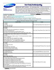
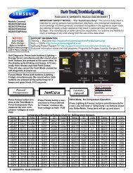
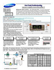
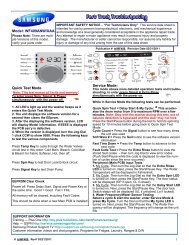
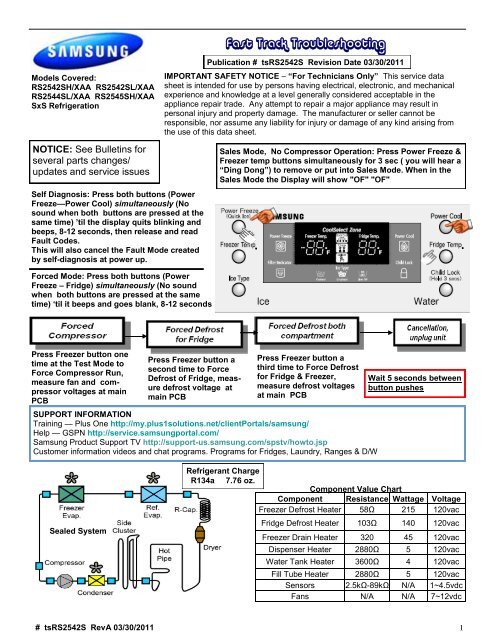
<strong>Fast</strong> <strong>Track</strong> <strong>Troubleshooting</strong>Models Covered:RS2542SH/XAA RS2542SL/XAARS2544SL/XAA RS2545SH/XAASxS RefrigerationPublication # tsRS2542S Revision Date 03/30/2011IMPORTANT SAFETY NOTICE – ―For Technicians Only‖ This service datasheet is intended for use by persons having electrical, electronic, and mechanicalexperience and knowledge at a level generally considered acceptable in theappliance repair trade. Any attempt to repair a major appliance may result inpersonal injury and property damage. The manufacturer or seller cannot beresponsible, nor assume any liability for injury or damage of any kind arising fromthe use of this data sheet.NOTICE: See Bulletins forseveral parts changes/updates and service issuesSelf Diagnosis: Press both buttons (PowerFreeze—Power Cool) simultaneously (Nosound when both buttons are pressed at thesame time) ‘til the display quits blinking andbeeps, 8-12 seconds, then release and readFault Codes.This will also cancel the Fault Mode createdby self-diagnosis at power up.Sales Mode, No Compressor Operation: Press Power Freeze &Freezer temp buttons simultaneously for 3 sec ( you will hear a―Ding Dong‖) to remove or put into Sales Mode. When in theSales Mode the Display will show "OF" "OF"Forced Mode: Press both buttons (PowerFreeze – Fridge) simultaneously (No soundwhen both buttons are pressed at the sametime) ‗til it beeps and goes blank, 8-12 secondsPress Freezer button onetime at the Test Mode toForce Compressor Run,measure fan and <strong>com</strong>pressorvoltages at mainPCBPress Freezer button asecond time to ForceDefrost of Fridge, measuredefrost voltage atmain PCBPress Freezer button athird time to Force Defrostfor Fridge & Freezer,measure defrost voltagesat main PCBSUPPORT INFORMATIONTraining — Plus One http://my.plus1solutions.net/clientPortals/samsung/Help — GSPN http://service.samsungportal.<strong>com</strong>/Samsung Product Support TV http://support-us.samsung.<strong>com</strong>/spstv/howto.jspCustomer information videos and chat programs. Programs for Fridges, Laundry, Ranges & D/WWait 5 seconds betweenbutton pushesSealed SystemRefrigerant ChargeR134a 7.76 oz.Component Value ChartComponent Resistance Wattage VoltageFreezer Defrost Heater 58Ω 215 120vacFridge Defrost Heater 103Ω 140 120vacFreezer Drain Heater 320 45 120vacDispenser Heater 2880Ω 5 120vacWater Tank Heater 3600Ω 4 120vacFill Tube Heater 2880Ω 5 120vacSensors 2.5kΩ-89kΩ N/A 1~4.5vdcFans N/A N/A 7~12vdc# tsRS2542S RevA 03/30/2011 1
DC FAN MOTORSBrushless DC Fan motors are used to save energy. The fans operate at two speeds. Fan speed information is read bythe Main PCB. If the fan speed exceeds 600 RPM or the speed is too slow, or stopped the fan drive circuit is disabled,After 10 seconds the circuit tries again with 3 seconds of DC voltage. If the fan continues this activity for 5 cycles, 10seconds off 3 seconds on, the fan drive circuit is disabled for 10 minutes.TO TEST THE FAN CIRCUIT VOLTAGE.Power off and back on to check the DC voltage to the motor, wait from 10 to 60 seconds for the fan voltage to kick in,and then check fan voltage, the average reading is 9 VDC. If you get 3 seconds of voltage every 10 seconds for the 5fan power up cycles, then the Main PCB is good.NOTE: You may need to put unit in FORCED FREEZE mode to activate the fans/<strong>com</strong>pressor.If the fan blade is blocked by ice, then defrost and check the motor again, after removing power from the unit.If the evaporator is ice blocked and thus blocking the air flow, the fan will over RPM and will be stopped. Remove iceand check the motor again. If everything is clear around the fan blade then the motor would be at fault. Continuous fanerrors will be displayed on the front panel display. PLEASE NOTE: The door switches control the evaporator fan motors.Have them closed to test the motors. Delay time 10 – 60 seconds.Samsung 'Refrigerator' Diagnostic Code Quick GuideError Items LED TROUBLE TESTINGI/M-SENSORR-SENSORDEFROST SENSOR OF RROOMR-FAN ERRORI/M FUNCTION ERRORCOOL SELECT ZONESENSORR-DEFROSTING ERROREXT-SENSORF-SENSORF-DEF-SENSORF-FAN ERRORC-FAN ERRORF-DEFROSTING ERRORUart ERRORCOMMUNICATIONL-M ERRORCOMMUNICATIONIce Maker Sensor Error- open or short-circuit, connector failure. Cause isalso a temperature reading > 122°or < -58 ° FRefrigerator Room Sensor Error- open or short-circuit, connector failure.Cause is also a temperature reading > 122°or < -58 ° F.Ref. Defrost Sensor Error- open or short-circuit, connector failure. Cause isalso a temperature reading > 122°or < -58 ° FThis error indicates the Refrigerator Evap Fan is not spinning at the correctRPM or the fan feedback line is open.This error indicates the Ice tray has not returned to level after an ice harvest.The error is displayed after three failed attempts.Cool Select Zone Sensor Error- open or short-circuit, connector failure.Cause is also a temperature reading > 122°or < -58 ° FRefrigerator Room defrost heater- open or short-circuit, connector failure, ordefective temperature fuse/bi-metal. Defrost on over 80 minutesAmbient Temp. Sensor Error- open or short-circuit, connector failure. Causeis also a temperature reading > 122°or < -58 ° FFreezer Compartment Sensor Error- open or short-circuit, connector failure.Cause is also a temperature reading > 122°or < -58 ° FFreezer Room Defrost Sensor Error- open or short-circuit, connector failure.Cause is also a temperature reading > 122°or < -58 ° FThis error indicates the Freezer Evap. Fan is not spinning at the correct RPMor the fan feedback line is open.This error indicates the Condenser Fan is not spinning at the correct RPM orthe fan feedback line is open.Freezer defrosting heater- open or short-circuit, connector failure, ordefective temperature fuse/bi-metal. Defrost on for over 80 minutesThis error is not applicable, if the error is detected during diagnostic testingplease ignore it.Communication error w ithin the Main PCBThe voltage at MAIN PCB Sensorbetw een 4.5V~1.0VThe voltage at MAIN PCB Sensorbetw een 4.5V~1.0VThe voltage at MAIN PCB Sensorbetw een 4.5V~1.0VFan voltage at MAIN PCB shall bebetw een 7V~12VReplace I/MThe voltage at MAIN PCB Sensorbetw een 4.5V~1.0VDisconnect defrost connectorfrom PCB, check resistanceThe voltage at MAIN PCB Sensorbetw een 4.5V~1.0VThe voltage at MAIN PCB Sensorbetw een 4.5V~1.0VThe voltage at MAIN PCB Sensorbetw een 4.5V~1.0VFan voltage at MAIN PCB shall bebetw een 7V~12VFan voltage at MAIN PCB shall bebetw een 7V~12VDisconnect defrost connectorfrom PCB, check resistanceNo Repair NecessaryReplace main PCBP-M ERRORCOMMUNICATIONCommunication betw een the Main PCB and KeypadCheck w iring in door & cabinet,Panel PCB, Main PCB# tsRS2542S RevA 03/30/2011 3
CN= Connector # for measuring voltages; () means go to connector #, pin # shown in () for voltage <strong>com</strong>mon.CN30 Sensors & Switches Component Name4-(CN76-1) F Def Sensor (Org-Gry) 2.3~4.2vdcVoltage on operating <strong>com</strong>ponentPin #s & wire colors on each connector to measure voltagesKey To Read PCB LayoutCN71 120vac1-(CN70-11) Cube Solenoid (Yel-Red)3-(CN70-11) Auger Mtr (Pnk-Red)5-(CN70-11) Ice-Valve Solenoid (Prp-Red)7-(CN70-11) Cover Ice Solenoid (W/Blk-RedCN70 120vac1-11 Water Tank (Blu-Red)5-11 Compressor & Dispenser Heater (S/Blu-Red)9-7 R-Def/Ice Pipe HTR (Wht-Org)13-7 F-Def HTR (Brn-Org)CN90 Ice Maker1-2 I/M Motor (Red-Blk) 12vdc3-4 I/M Sensor (Wht-Wht) 2.3~3.3vdc5-8 Test Sw (Gry-S/Blu) 5vdc6-8 Horizontal Sw (Blu-S/Blu) 5vdc7-8 Check Sw (Prp-S/Blu) 5vdcCN50 Panel DisplayCN30 Sensors1-2 F Door SW (W/Red-Brn) 5vdc5-6 R Door SW (W/Blu-Brn) 5vdc3-2 F Sensor (Yel-Brn) 3.5~4.2vdc4-2 F-Def Sensor (Blu-Brn) 2.3~4.2vdc7-6 R Sensor (Gry-Brn) 2.4~2.8vdc8-6 R-Def Sensor (Prp-Brn) 2~4.2vdc9 -10 Water Sw (Wht-Blk) 120vacCN311-4 Ambient Sensor (Wht-Wht) 1.2~2 vdc2-3 Ice SW (Org-Org) 5vdcCN10 Transformer1-3 (Blk-Red) 120 VACCN72 Fans6-7 F-Fan (Yel-Gry) 7~11vdc5-7 R-Fan (Org-Gry) 7~11vdc4-7 C-Fan (S/Blu-Gry) 7~11vdc3 F-Fan control (Blk)2 R-Fan Control (Brn)1 C-Fan Control (Red)# tsRS2542S RevA 03/30/2011 4
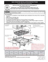
Model: RS2542, RS2544, RS2545RS2644, RS2666# tsRS2542S RevA 03/30/2011 5