Fast Track Troubleshooting - MSAWorld.com
Fast Track Troubleshooting - MSAWorld.com
Fast Track Troubleshooting - MSAWorld.com
- No tags were found...

You also want an ePaper? Increase the reach of your titles
YUMPU automatically turns print PDFs into web optimized ePapers that Google loves.
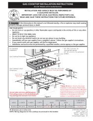
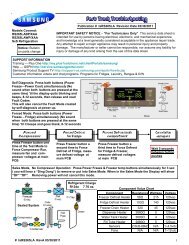
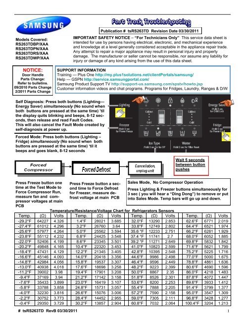
<strong>Fast</strong> <strong>Track</strong> <strong>Troubleshooting</strong>Models Covered:RS263TDBP/XAARS263TDPN/XAARS263TDRS/XAARS263TDWP/XAANOTICE:Door HandleParts Change:Refer to bulletins.09/2010 Parts Change2/2011 Parts ChangePublication # tsRS263TD Revision Date 03/30/2011IMPORTANT SAFETY NOTICE – ―For Technicians Only‖ This service data sheet isintended for use by persons having electrical, electronic, and mechanical experienceand knowledge at a level generally considered acceptable in the appliance repair trade.Any attempt to repair a major appliance may result in personal injury and propertydamage. The manufacturer or seller cannot be responsible, nor assume any liability forinjury or damage of any kind arising from the use of this data sheet.SUPPORT INFORMATIONTraining — Plus One http://my.plus1solutions.net/clientPortals/samsung/Help — GSPN http://service.samsungportal.<strong>com</strong>/Samsung Product Support TV http://support-us.samsung.<strong>com</strong>/spstv/howto.jspCustomer information videos and chat programs. Programs for Fridges, Laundry, Ranges & D/WSelf Diagnosis: Press both buttons (Lighting—Energy Saver) simultaneously (No sound whenboth buttons are pressed at the same time) ‘tilthe display quits blinking and beeps, 8-12 seconds,then release and read Fault Codes.This will also cancel the Fault Mode created byself-diagnosis at power up.Forced Mode: Press both buttons (Lighting –Fridge) simultaneously (No sound when bothbuttons are pressed at the same time) ‗til itbeeps and goes blank, 8-12 secondsWait 5 secondsbetween buttonpushesPress Freeze button onetime at the Test Mode toForce Compressor Run,measure fan and <strong>com</strong>pressorvoltages at mainPCBPress Freeze button a secondtime to Force Defrostfor Freezer, measure defrostvoltage at main PCBSales Mode, No Compressor OperationPress Lighting & Freezer buttons simultaneously for3 sec ( you will hear a ―Ding Dong‖) to remove or putinto Sales Mode. Temp bars will go up and down.Temperature/Resistance/Voltage Chart for Refrigerators SensorsTemp. (Ω) Volts Temp. (Ω) Volts Temp. (Ω) Volts Temp. (Ω) Volts-29.2°F 64227 4.326 1.4°F 28021 3.685 32.0°F 13290 2.853 62.6°F 6771 2.019-27.4°F 61012 4.296 3.2°F 26760 3.64 33.8°F 12749 2.802 64.4°F 6521 1.974-25.6°F 57977 4.264 5.0°F 25562 3.594 35.6 °F 12233 2.751 66.2°F 6281 1.929-23.8°F 55112 4.232 6.8°F 24425 3.548 37.4 °F 11741 2.7 68.0°F 6052 1.885-22.0°F 52406 4.199 8.6°F 23345 3.501 39.2 °F 11271 2.649 69.8°F 5832 1.842-20.2°F 49848 4.165 10.4°F 22320 3.453 41.0°F 10823 2.599 71.6°F 5621 1.799-18.4°F 47431 4.129 12.2°F 21345 3.405 42.8°F 10395 2.548 75.2°F 5225 1.716-16.6°F 45146 4.093 14.0°F 20418 3.356 44.6°F 9986 2.498 77.0°F 5000 1.675-14.8°F 42984 4.056 15.8°F 19537 3.307 46.4°F 9596 2.449 78.8°F 4861 1.636-13.0°F 40938 4.018 17.6°F 18698 3.258 48.2°F 9223 2.399 80.6°F 4690 1.596-11.2°F 39002 3.98 19.4°F 17901 3.208 50.0°F 8867 2.35 86.0°F 4218 1.483-9.4°F 37169 3.94 21.2°F 17142 3.158 51.8°F 8526 2.301 87.8°F 4072 1.447-7.6°F 35433 3.899 23.0°F 16419 3.107 53.6°F 8200 2.253 89.6°F 3933 1.412-5.8°F 33788 3.858 24.8°F 15731 3.057 55.4°F 7888 2.205 91.4°F 3799 1.377-4.0°F 32230 3.816 26.6°F 15076 3.006 57.2°F 7590 2.158 95.0°F 3547 1.309-2.2°F 30752 3.773 28.4°F 14452 2.955 59.0°F 7305 2.111 96.8°F 3428 1.277-0.4°F 29350 3.729 30.2°F 13857 2.904 60.8°F 7032 2.064 100.4°F 3204 1.213# tsRS263TD RevB 03/30/2011 1
CN= Connector # for measuring voltages; () means go to connector #, pin # shown in () for voltage <strong>com</strong>mon.CN30 Sensors & Switches Component Name4-(CN76-1) F Def Sensor (Org-Gry) 2.3~4.2vdcVoltage on operating <strong>com</strong>ponentPin #s & wire colors on each connector to measure voltagesKey To Read PCB LayoutCN781-2 Fz LED (Brn-Gry)3-5 FF Low LED (S/Blu-Gry)4-5 FF Upper LED (Prp-Gry)CN90 Ice Maker4-8 Sensor I/M eject (Wht-S/Blu) 2.3~3.3vdc5-8 Test Sw (Gry-S/Blu) 5vdc6 Full Hall IC out (Blu)7 Horiz Hall IC out (Prp)CN76 F, R, C Fans2-1 C Fan (S/Blu-Gry) 7-11vdc3-1 R Fan (Org-Gry) 7-11vdc4-1 F Fan (Yel-Gry) 7-11vdc5 F Fan FG (Brn)6 R Fan FG (Red)7 C Fan FG (Blu)10– GndCN51 DisplayCN504-5 5vdc (W/Yel-Gry)6-10 Ice Sw (Pnk-Gry)7-10 Water Sw (Blu-Gry)CN79 To Comp Inverter Board2-(CN40-4) (Brn-Gry) 5vdc4-(CN40-4) Comp control (Org-Gry) 2.5vdcCN40 Sensors & Switches2-1 Ambient Sensor (Yel-Yel) 1.2~2vdc3-4 Frz Dr Sw (W/Grn-Gry)5-(CN50-5) Fz Sensor (Yel-Gry) 3.5~4.2vdc6-(CN50-5) F Def Sensor (Blu-Gry) 2.3~4.2vdc7-8 R Door Sw (W/Red-Gry)9-(CN50-5) R Sensor (S/Blu-Gry) 2~4.2vdc11-(CN50-5) R Def Sensor (Prp-Gry) 2~4.2vdcComponent Value ChartComponent Resistance Wattage VoltageFreezer Defrost Heater 66Ω 218 120vacFridge Defrost Heater 103Ω 140 120vacDispenser Heater 2057Ω 7 120vacFill Tube Heater 3130Ω 4.6 120vacSensors 2.5kΩ-89kΩ N/A 1~4.5vdcFans N/A N/A 7~12vdcCN70/CN71 All 120vac1 Common N (Blk)3 Common L (Red)5-9 F Defrost (Brn-Org)7-9 R Defrost/Fill Tube (Wht-Org)9 Hearer Common (Org)13– Common N (Blk)15-3 Disp Heater (Blu-Red)CN73 All 120vac1-(CN70-9) Dispenser Valve (W/Blk-Red)7-(CN70-9) I/M Valve Fridge (Prp-Red)9-(CN70-9) Auger Motor (Pnk-Red)11-(CN70-9) Cube Solenoid (Yel-Red)# tsRS263TD RevB 03/30/2011 2
R Def SensorCN76# tsRS263TD RevB 03/30/2011 3
FLEX TRAY Ice MakersWhen the initial power is applied, the ice tray will stand by for 2 hours.After the 2-hour standby time, the Ice Maker Sensor will check thetemperature , when it is lower than 1.5℉ for more than 5 minutes, itwill do a harvest, with or without ice in the tray, then fill with water. 58minutes after water is supplied to the Ice Tray, the Ice Maker Sensortemperature will be checked. When the Ice Maker Sensor maintainslower than 1.5℉ for 5 minutes, it <strong>com</strong>pletes the harvest (if the ice binis not sensed as full). Thermistor senses temperature to determinewater fill on newer unitsFilling the trayAfter the water fill is <strong>com</strong>pleted, the ice maker sensor will evaluate thewater volume one and a half minutes later. When it detects no or lowwater level, it will add more water. First supply time will be 1.5 sec,next one will be 1 sec and the last will be 2 sec.Guide – Bin FullIce Maker Test ButtonIce Maker ThermistorNO Error LED Display1 ICE MAKER SENSOR Right-1 LED ONShattered Ice – Flex TrayWhen all ice shatters, it's because of a badtray or ice cube temp that is too cold (lowerthan -5 degrees). In some areas, there arewater issues that can also cause shatteredcubes. The temp in the freezer should nothave any effect on this issue, as long as it’sbelow 1.5 degrees F, as a properly installedsensor will not read the freezer temp, only thewater/ice temp.Check the Ice tray for defects in the plastic.Ice that is too cold will shatter duringharvest. This can be from the (1) sensor notreading the correct temp (2) or the sensor notmounted correctly (3). By programming theicemaker offset value to a lower number (4),the board not understanding the reading.To check the sensor, you must check the traytemp (not air temp) and <strong>com</strong>pare it to the sensorreading. The sensor should read 3.7 voltsat the main board connector when the cubetemperature is 1 degree. After the fill, the sensorwill read water temp 1.5 to 2.2 volts.To clear offsets, put unit into Diagnosticsmode.Please note, some shattering is normal fora flex tray icemaker.2 R-DEFROST SENSOR Right-3 LED ON3 R-SENSOR Right-4 LED ONRefrigerant ChargeR134a 7.41 oz.4 R-FAN ERROR Right-5 LED ON5 R-DEFROST ERROR Right 6LED ONSealed System6ICE MAKER FUNCTIONERRORRight-7 LED ON7 EXIT-SENSOR Left- 1 LED ON8 FREEZER SENSOR Left- 2 LED ON9 F-DEFROST SENSOR Left- 3 LED ON10 FREEZER FAN ERROR Left-4 LED ON11 C-FAN ERROR Left-5 LED ONCompressor → Condenser →Side Cluster →Hot Pipe→ Dryer → R Capillary → R Evaporator→ F Evaporator → Suction Pipe →Compressor12 F-DEFROST ERROR Left-7 LED ON# tsRS263TD RevB 03/30/2011 4
Compressor & System Operation TestingTEST BEFORE INTERPRETING LED BLINKING FREQUENCYCompressor not running1. Activate Forced Compressor Operation, wait 2 minutes (in case of high head pressure)2. If <strong>com</strong>pressor doesn’t start, check CN75 for 2~2.8vdc (if not there replace Main PCB)3. Check for 120vac to inverter PCB CN02 L-N4. If voltage is OK, remove power, disconnect CN03 (Inverter PCB) and check resistance to the windings.Aproxametly10 ohms. If not correct , inspect wire harness, if OK replace <strong>com</strong>pressor.5. Disconnect CN02 (SMPS PCB), check resistance to Overload , if open replace overload.CN79 To Comp Inverter Board2-(CN40-4) (Brn-Gry) 5vdc4-(CN40-4) Comp control (Org-Gry) 2~2.8vdcCN04 Compressor Control2- (CN40-4) 5vdc (Brn-Gry)4 Comp Signal (Org)CN02 Overload& A/C Line1 OLP (Brn)3 OLP (S/Blu)3 L (Blk)1 N (Red)CN03 Compressor Windings1 Compressor (Blue)3 Compressor (Prp)5 Compressor (Wht)ProtectionFunctionsLED Blinking Frequency Test ReplaceStarting FailureCheck the Inverter PCB & CompRelay ConnectorsConnectors OK,replace Inverter PCB, if same,replace <strong>com</strong>pressorSPM FaultDetectingPosition FailureIf blinking after reset,Check Inverter Connectors,Check System for restriction & refrigerant, if OKreplace Inverter, if same, replace <strong>com</strong>pressorConnectors measure OK, replace <strong>com</strong>pressor, ifsame, replace Inverter PCBMotor Locked Compressor Locking CompressorLow VoltageOver VoltageCompressor Locking, check inputvoltageCompressor Locking, check inputvoltageReplace Inverter PCB, if same, replaceCompressorReplace Inverter PCB, if same, replaceCompressor# tsRS263TD RevB 03/30/2011 5
WaterRS263TDDispenser issueICEThe models listed above are a new design incorporating a two stage dispenser leverIf water is selected press the lever a short distanceIf Ice is selected press the lever in until the lever is slightly past straight up and down# tsRS263TD RevB 03/30/2011 6