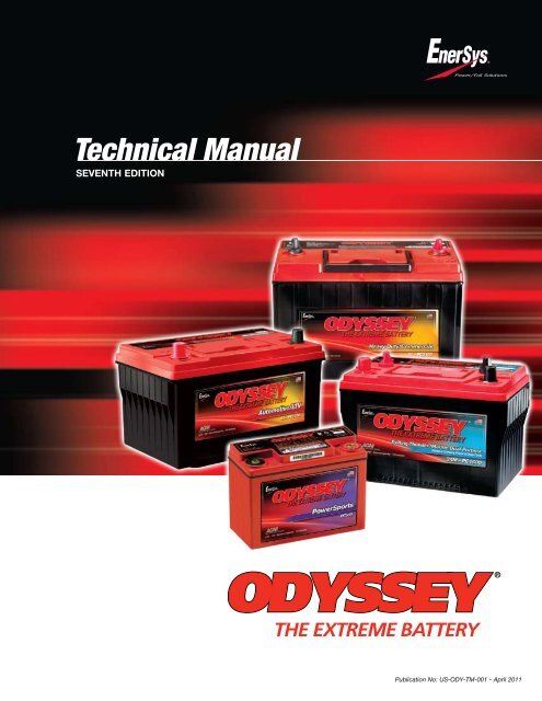
Technical Manual - ODYSSEY Batteries
Technical Manual - ODYSSEY Batteries
Technical Manual - ODYSSEY Batteries
- No tags were found...
Create successful ePaper yourself
Turn your PDF publications into a flip-book with our unique Google optimized e-Paper software.
Extended discharge characteristicsIn addition to its excellent pulse discharge capabilities, the <strong>ODYSSEY</strong> ® battery can deliver many deep discharge cycles,yet another area where the <strong>ODYSSEY</strong> battery outperforms a conventional SLI battery, which can deliver only a few deepdischarge cycles.The following twenty graphs show detailed discharge characteristics of the entire <strong>ODYSSEY</strong> battery line. The end of dischargevoltage in each case is 10.02V per battery or 1.67 volts per cell (VPC). Each graph shows both constant current (CC)and constant power (CP) discharge curves at 25ºC (77ºF). The table next to each graph shows the corresponding energyand power densities. The battery run times extend from 2 minutes to 20 hours.Watts or amps per 12V unitPC310 & ER8 performance data at 25°C, per 12V module10001001010.1Watts0.01 0.1 1 10 100Hours to 10.02V @ 25˚C (77˚F)Time Watts Amps Capacity Energy Energy and power densities(W) (A) (Ah) (Wh) W/liter Wh/liter W/kg Wh/kgAmps2 min 738 80.8 2.7 24.6 613.2 20.4 273.3 9.15 min 473 43.2 3.6 39.4 393.3 32.8 175.3 14.610 min 312 26.0 4.4 53.1 259.4 44.1 115.6 19.715 min 236 19.0 4.8 59.0 196.0 49.0 87.4 21.820 min 191 15.0 5.0 62.9 158.4 52.3 70.6 23.330 min 139 10.8 5.4 69.3 115.1 57.6 51.3 25.745 min 98 7.6 5.7 73.9 81.8 61.4 36.5 27.41 hr 76 6.0 6.0 76.4 63.5 63.5 28.3 28.32 hr 41 3.2 6.5 81.0 33.7 67.3 15.0 30.03 hr 28 2.3 6.8 82.8 22.9 68.8 10.2 30.74 hr 21 1.8 7.0 83.7 17.4 69.6 7.8 31.05 hr 17 1.4 7.2 84.5 14.0 70.2 6.3 31.38 hr 11 0.9 7.6 86.1 8.9 71.5 4.0 31.910 hr 9 0.8 7.8 86.8 7.2 72.1 3.2 32.220 hr 5 0.4 8.6 90.5 3.8 75.2 1.7 33.5Watts or amps per 12V unitER15 performance data at 25°C, per 12V module1000100101WattsAmps00.01 0.1 1 10 100Hours to 10.02V @ 25˚C (77˚F)Time Watts Amps Capacity Energy Energy and power densities(W) (A) (Ah) (Wh) W/litre Wh/litre W/kg Wh/kg2 min 1320 127.1 4.2 44.0 612.2 20.4 231.6 7.75 min 768 70.7 5.9 64.0 356.2 29.7 134.7 11.210 min 485 43.6 7.3 80.9 225.1 37.5 85.2 14.215 min 365 32.4 8.1 91.4 169.5 42.4 64.1 16.020 min 297 26.1 8.7 99.0 137.8 45.9 52.1 17.430 min 220 19.1 9.6 109.8 101.9 50.9 38.5 19.345 min 161 13.8 10.4 120.6 74.6 55.9 28.2 21.21 hr 128 10.9 10.9 127.8 59.3 59.3 22.4 22.42 hr 73 6.1 12.2 145.2 33.7 67.3 12.7 25.53 hr 51 4.3 12.9 153.7 23.8 71.3 9.0 27.04 hr 40 3.3 13.3 159.6 18.5 74.0 7.0 28.05 hr 33 2.7 13.7 163.8 15.2 76.0 5.7 28.78 hr 21 1.8 14.4 171.8 10.0 79.7 3.8 30.110 hr 18 1.5 14.5 175.2 8.1 81.3 3.1 30.720 hr 9 0.8 15.2 183.6 4.3 85.2 1.6 32.24 www.odysseybattery.comPublication No: US-ODY-TM-001 - April 2011
®Time Watts Amps Capacity Energy Energy and power densities(W) (A) (Ah) (Wh) W/liter Wh/liter W/kg Wh/kg2 min 1182 112.0 3.40 35.5 450.7 13.5 218.9 6.65 min 786 71.9 5.75 62.9 299.7 24.0 145.6 11.610 min 517.2 46.3 7.90 87.9 197.2 33.5 98.8 16.315 min 390.6 34.5 8.60 97.65 148.9 37.2 72.3 18.120 min 316.2 27.7 9.10 104.35 120.6 39.8 58.6 19.330 min 230.4 20.0 10.0 115.2 87.85 43.9 42.7 21.345 min 165 14.2 10.65 123.75 62.9 47.2 30.6 22.91 hr 129 11.0 11.0 129.0 49.2 49.2 23.9 23.92 hr 70.2 5.9 11.8 140.4 26.8 53.5 13.0 26.03 hr 48.5 4.1 12.3 145.4 18.5 55.5 9.0 26.94 hr 37.3 3.1 12.4 149.3 14.2 56.9 6.9 27.65 hr 30.5 2.5 12.5 152.4 11.6 58.1 5.6 28.28 hr 19.9 1.7 13.6 159.4 7.6 60.8 3.7 29.510 hr 16.3 1.3 13.0 163.2 6.2 62.2 3.0 30.220 hr 9 0.74 14.8 178.8 3.4 68.2 1.7 33.1Watts or amps per 12V unitPC535 & ER18 performance data at 25°C, per 12V moduleWatts Amps1000010001001010.10.01 0.1 1 10 100Hours to 10.02V @ 25˚C (77˚F)Time Watts Amps Capacity Energy Energy and power densities(W) (A) (Ah) (Wh) W/liter Wh/liter W/kg Wh/kg2 min 1361 128.1 4.3 45.3 680.8 22.7 238.7 8.05 min 648 64.4 5.4 54.0 324.2 27.0 113.7 9.510 min 415 39.6 6.7 70.6 207.75 35.3 72.8 12.415 min 313 29.2 7.3 78.2 156.4 39.1 54.8 13.720 min 254 23.5 7.8 83.8 127.0 41.9 44.5 14.730 min 187 16.9 8.5 93.3 93.4 46.7 32.7 16.445 min 136 12.2 9.2 101.7 67.9 50.9 23.8 17.81 hr 107 9.6 9.6 107.4 53.7 53.7 18.8 18.82 hr 60 5.3 10.6 120.0 30.0 60.0 10.5 21.13 hr 42 3.7 11.1 126.0 21.0 63.1 7.4 22.14 hr 32 2.9 11.6 129.6 16.2 64.9 5.7 22.75 hr 26 2.3 11.5 132.0 13.2 66.1 4.6 23.28 hr 17 1.5 12.0 134.4 8.4 67.25 3.0 23.610 hr 14 1.2 12.0 138.0 6.9 69.1 2.4 24.220 hr 7 0.7 14.0 144.0 3.6 72.1 1.3 25.3PC545 & ER20 performance data at 25°C, per 12V moduleWatts or amps per 12V unitWatts Amps1000010001001010.10.01 0.1 1 10 100Hours to 10.02V @ 25˚C (77˚F)Time Watts Amps Capacity Energy Energy and power densities(W) (A) (Ah) (Wh) W/liter Wh/liter W/kg Wh/kg2 min 1582 154.7 5.20 52.70 536.10 17.90 255.10 8.505 min 986 91.6 7.60 82.20 334.35 27.90 159.10 13.3010 min 635 57.1 9.50 105.90 215.40 35.90 102.50 17.1015 min 478 42.3 10.60 119.40 161.90 40.50 77.0 19.3020 min 385 33.8 11.30 128.40 130.60 43.50 62.10 20.7030 min 281 24.4 12.20 140.70 95.40 47.70 45.40 22.7045 min 202 17.4 13.05 151.65 68.50 51.40 32.60 24.501 hr 159 13.6 13.60 159.0 53.90 53.90 25.65 25.652 hr 87 7.3 14.60 174.0 29.50 59.0 14.0 28.103 hr 61 5.1 15.30 181.80 20.50 61.60 9.80 29.304 hr 47 3.9 15.60 187.20 15.90 63.45 7.55 30.205 hr 38 3.2 16.0 192.0 13.0 65.10 6.20 31.08 hr 25 2.1 16.80 201.60 8.50 68.30 4.10 32.5010 hr 20 1.7 17.0 204.0 6.90 69.15 3.30 32.9020 hr 11 0.9 18.0 216.0 3.70 73.20 1.70 34.80PC625 & ER22 performance data at 25°C, per 12V moduleWatts or amps per 12V unitWatts Amps1000010001001010.10.01 0.1 1 10 100Hours to 10.02V @ 25˚C (77˚F)www.odysseybattery.comPublication No: US-ODY-TM-001 - April 20115
Watts or amps per 12V unitPC680 & ER25 performance data at 25°C, per 12V moduleWatts Amps1000010001001010.10.01 0.1 1 10 100Hours to 10.02V @ 25˚C (77˚F)Time Watts Amps Capacity Energy Energy and power densities(W) (A) (Ah) (Wh) W/liter Wh/liter W/kg Wh/kg2 min 1486 143.0 4.8 49.5 601.4 20.0 212.3 7.15 min 792 78.8 6.6 66.0 320.5 26.7 113.1 9.410 min 512 49.3 8.4 87.1 207.3 35.25 73.2 12.415 min 389 36.7 9.2 97.4 157.6 39.4 55.6 13.920 min 318 29.6 9.8 104.9 128.7 42.5 45.4 15.030 min 236 21.6 10.8 118.2 95.7 47.8 33.8 16.945 min 173 15.6 11.7 130.1 70.2 52.6 24.8 18.61 hr 138 12.3 12.3 138.0 55.8 55.8 19.7 19.72 hr 79 6.9 13.8 157.2 31.8 63.6 11.2 22.53 hr 56 4.8 14.4 166.5 22.5 67.4 7.9 23.84 hr 43 3.7 14.8 172.8 17.5 69.9 6.2 24.75 hr 35 3.0 15.0 177.0 14.3 71.6 5.1 25.38 hr 23 2.0 16.0 187.2 9.5 75.75 3.3 26.710 hr 19 1.6 16.0 192.0 7.8 77.7 2.7 27.420 hr 10 0.8 16.0 204.0 4.1 82.6 1.5 29.1ER30 performance data at 25°C, per 12V module Time Watts(W)Watts or amps per 12V unit100001000100101WattsAmps0.01 0.1 1 10 100Hours to 10.02V @ 25ºC (77ºF)Amps(A)Capacity(Ah)Energy(Wh)Energy and power densitiesW/litre Wh/litre W/kg Wh/kg2 min 2793.6 268.3 8.9 93.1 755.0 25.2 310.4 10.35 min 1744.8 161.3 13.4 145.4 471.6 39.3 193.9 16.210 min 1126.2 101.4 16.9 187.7 304.4 50.7 125.1 20.915 min 847.8 75.3 18.8 212.0 229.1 57.3 94.2 23.620 min 685.8 60.3 20.1 228.6 185.4 61.8 76.2 25.430 min 501.6 43.6 21.8 250.8 135.6 67.8 55.7 27.945 min 361.8 31.1 23.3 271.4 97.8 73.3 40.2 30.21 hr 284.4 24.3 24.3 284.4 76.9 76.9 31.6 31.62 hr 156.6 13.2 26.4 313.2 42.3 84.6 17.4 34.83 hr 109.8 9.2 27.6 329.4 29.7 89.0 12.2 36.64 hr 84.6 7.1 28.4 338.4 22.9 91.5 9.4 37.65 hr 69.6 5.8 29.0 348.0 18.8 94.1 7.7 38.78 hr 45.6 3.8 30.4 364.8 12.3 98.6 5.1 40.510 hr 37.2 3.2 32.0 372.0 10.1 100.5 4.1 41.320 hr 20.4 1.7 34.0 408.0 5.5 110.3 2.3 45.3Watts or amps per 12V unitPC925 & ER35 performance data at 25°C, per 12V moduleWatts Amps1000010001001010.01 0.1 1 10 100Hours to 10.02V @ 25˚C (77˚F)Time Watts Amps Capacity Energy Energy and power densities(W) (A) (Ah) (Wh) W/liter Wh/liter W/kg Wh/kg2 min 2381 224.8 7.5 79.3 615.8 20.5 201.8 6.75 min 1446 142.8 11.9 120.5 374.0 31.2 122.5 10.210 min 954 90.6 15.4 162.2 246.75 42.0 80.9 13.715 min 726 67.4 16.9 181.5 187.8 46.9 61.5 15.420 min 592 54.2 17.9 195.2 153.0 50.5 50.1 16.530 min 436 39.2 19.6 217.8 112.7 56.3 36.9 18.545 min 316 28.1 21.1 236.7 81.6 61.2 26.75 20.11 hr 250 21.9 21.9 249.6 64.6 64.6 21.2 21.22 hr 138 11.9 23.8 276.0 35.7 71.4 11.7 23.43 hr 96 8.3 24.9 288.0 24.8 74.5 8.1 24.44 hr 74 6.4 25.6 297.6 19.2 77.0 6.3 25.25 hr 61 5.2 26.0 303.0 15.7 78.4 5.1 25.78 hr 40 3.4 27.2 316.8 10.2 81.9 3.4 26.910 hr 32 2.8 27.5 324.0 8.4 83.8 2.75 27.520 hr 17 1.5 30.0 348.0 4.5 90.0 1.5 29.56 www.odysseybattery.comPublication No: US-ODY-TM-001 - April 2011
®Time Watts Amps Capacity Energy Energy and power densities(W) (A) (Ah) (Wh) W/litre Wh/litre W/kg Wh/kg2 min 3307.2 326.8 10.9 110.2 668.1 22.3 264.6 8.85 min 2332.8 219.5 18.3 194.4 471.3 39.3 186.6 15.610 min 1575.0 143.2 23.9 262.5 318.2 53.0 126.0 21.015 min 1200.0 107.2 26.8 300.0 242.4 60.6 96.0 24.020 min 974.4 86.1 28.7 324.8 196.8 65.6 78.0 26.030 min 713.4 62.0 31.0 356.7 144.1 72.1 57.1 28.545 min 513.0 44.0 33.0 384.8 103.6 77.7 41.0 30.81 hr 402.6 34.3 34.3 402.6 81.3 81.3 32.2 32.22 hr 220.8 18.5 37.0 441.6 44.6 89.2 17.7 35.33 hr 154.2 12.9 38.7 462.6 31.2 93.5 12.3 37.04 hr 120.0 10.0 40.0 480.0 24.2 97.0 9.6 38.45 hr 99.0 8.2 41.0 495.0 20.0 100.0 7.9 39.68 hr 66.0 5.5 44.0 528.0 13.3 106.7 5.3 42.210 hr 55.2 4.6 46.0 552.0 11.2 111.5 4.4 44.220 hr 32.4 2.7 54.0 648.0 6.5 130.9 2.6 51.8ER40 performance data at 25°C, per 12V moduleWatts or amps per 12V unitWatts Amps10001001010.10.01 0.1 1 10 100Hours to 10.02V @ 25˚C (77˚F)Time Watts Amps Capacity Energy Energy and power densities(W) (A) (Ah) (Wh) W/liter Wh/liter W/kg Wh/kg2 min 3580 337.9 11.3 119.2 613.0 20.4 205.8 6.95 min 1992 199.1 16.6 165.9 341.1 28.4 114.5 9.510 min 1338 127.9 21.7 227.5 229.1 38.9 76.9 13.115 min 1026 96.0 24.0 256.5 175.7 43.9 59.0 14.720 min 840 77.5 25.6 277.2 143.8 47.5 48.3 15.930 min 624 56.6 28.3 312.0 106.8 53.4 35.9 17.945 min 458 40.8 30.6 343.4 78.4 58.8 26.3 19.71 hr 364 32.1 32.1 363.6 62.25 62.25 20.9 20.92 hr 203 17.7 35.4 406.8 34.8 69.7 11.7 23.43 hr 143 12.3 36.9 428.4 24.5 73.4 8.2 24.64 hr 110 9.5 38.0 441.6 18.9 75.6 6.3 25.45 hr 91 7.7 38.5 453.0 15.5 77.6 5.2 26.08 hr 59 5.0 40.0 475.2 10.2 81.4 3.4 27.310 hr 48 4.1 41.0 480.0 8.2 82.2 2.8 27.620 hr 25 2.2 44.0 504.0 4.3 86.3 1.5 29.0Watts or amps per 12V unitPC1200 performance data at 25°C, per 12V moduleWatts Amps1000010001001010.01 0.1 1 10 100Hours to 10.02V @ 25˚C (77˚F)TimeWatts(W)Amps(A)Capacity(Ah)Energy(Wh)Energy and power densitiesW/litre Wh/litre W/kg Wh/kg2 min 3982 384.3 12.8 132.7 396.6 13.2 192.4 6.45 min 2846 264.8 22.1 237.2 283.5 23.6 137.5 11.510 min 1993 180.8 30.1 332.1 198.5 33.1 96.3 16.015 min 1561 139.7 34.9 390.3 155.5 38.9 75.4 18.920 min 1294 114.8 38.3 431.4 128.9 43.0 62.5 20.830 min 976 85.5 42.8 487.9 97.2 48.6 47.1 23.645 min 722 62.6 46.9 541.2 71.9 53.9 34.9 26.11 hr 577 49.7 49.7 576.6 57.4 57.4 27.9 27.92 hr 326 27.7 55.4 652.1 32.5 64.9 15.8 31.53 hr 230 19.4 58.3 689.8 22.9 68.7 11.1 33.34 hr 179 15.0 60.1 714.0 17.8 71.1 8.6 34.55 hr 146 12.3 61.5 731.6 14.6 72.9 7.1 35.38 hr 96 8.0 64.2 766.2 9.5 76.3 4.6 37.010 hr 78 6.5 65.5 782.0 7.8 77.9 3.8 37.820 hr 42 3.5 69.9 832.1 4.1 82.9 2.0 40.2PC1220 performance data at 25°C, per 12V moduleWatts or amps per 12V unitWatts Amps1000010001001010.01 0.1 1 10 100Hours to 10.02V @ 25ºC (77ºF)www.odysseybattery.comPublication No: US-ODY-TM-001 - April 20117
Watts or amps per 12V unit75-PC1230 & 75/86-PC1230 performance data at 25°C,per 12V module10000100010010WattsAmps10.01 0.1 1 10Hours to 10.02V @ 25ºC (77ºF)100TimeWatts(W)Amps(A)Capacity(Ah)Energy(Wh)Energy and power densitiesW/litre Wh/litre W/kg Wh/kg2 min 4561.7 432.9 14.3 150.5 531.5 17.5 221.4 7.35 min 2936.3 266.5 22.1 243.7 342.1 28.4 142.5 11.810 min 1919.1 169.6 28.3 320.5 223.6 37.3 93.2 15.615 min 1451.2 126.6 31.7 362.8 169.1 42.3 70.4 17.620 min 1176.0 101.8 33.9 391.6 137.0 45.6 57.1 19.030 min 861.5 73.8 36.9 430.8 100.4 50.2 41.8 20.945 min 621.9 52.8 39.6 466.4 72.5 54.3 30.2 22.61 hr 489.8 41.4 41.4 489.8 57.1 57.1 23.8 23.82 hr 270.1 22.6 45.3 540.2 31.5 62.9 13.1 26.23 hr 189.0 15.8 47.4 567.1 22.0 66.1 9.2 27.54 hr 146.4 12.2 48.8 585.7 17.1 68.2 7.1 28.45 hr 120.1 10.0 50.0 600.6 14.0 70.0 5.8 29.28 hr 79.2 6.6 52.7 633.2 9.2 73.8 3.8 30.710 hr 65.0 5.4 54.1 650.1 7.6 75.7 3.2 31.620 hr 35.7 3.0 59.4 713.5 4.2 83.1 1.7 34.6Watts or amps per 12V unitPC1350 performance data at 25°C, per 12V moduleWatts Amps1000010001001010.01 0.10 1 10Hours to 10.02V @ 25ºC (77ºF)100TimeWatts(W)Amps(A)Capacity(Ah)Energy(Wh)Energy and power densitiesW/litre Wh/litre W/kg Wh/kg2 min 5477.3 527.2 17.6 182.6 438.2 14.6 199.9 6.75 min 3758.2 349.4 29.1 313.2 300.7 25.1 137.2 11.410 min 2601.6 235.8 39.3 433.6 208.1 34.7 94.9 15.815 min 2037.0 182.0 45.5 509.3 163.0 40.7 74.3 18.620 min 1691.9 149.8 49.9 564.0 135.4 45.1 61.7 20.630 min 1282.0 112.1 56.0 641.0 102.6 51.3 46.8 23.445 min 955.0 82.5 61.9 716.2 76.4 57.3 34.9 26.11 hr 767.6 65.8 65.8 767.6 61.4 61.4 28.0 28.02 hr 440.8 37.3 74.5 881.7 35.3 70.5 16.1 32.23 hr 313.6 26.4 79.1 940.8 25.1 75.3 11.4 34.34 hr 244.8 20.5 82.0 979.2 19.6 78.3 8.9 35.75 hr 201.4 16.8 84.2 1006.9 16.1 80.5 7.3 36.78 hr 132.5 11.1 88.5 1059.8 10.6 84.8 4.8 38.710 hr 108.3 9.0 90.5 1082.7 8.7 86.6 4.0 39.520 hr 57.3 4.8 96.5 1146.8 4.6 91.7 2.1 41.925-PC1400 & 35-PC1400 performance data at 25°C,per 12V moduleWatts or amps per 12V unit10000100010010WattsAmps10.01 0.1 1 10Hours to 10.02V @ 25ºC (77ºF)100TimeWatts(W)Amps(A)Capacity(Ah)Energy(Wh)Energy and power densitiesW/litre Wh/litre W/kg Wh/kg2 min 5308.3 499.5 16.5 175.2 576.1 19.0 233.8 7.75 min 3439.7 315.8 26.2 285.5 373.3 31.0 151.5 12.610 min 2261.4 203.0 33.9 377.7 245.4 41.0 99.6 16.615 min 1715.5 151.9 38.0 428.9 186.2 46.5 75.6 18.920 min 1393.0 122.2 40.7 463.9 151.2 50.3 61.4 20.430 min 1022.9 88.6 44.3 511.5 111.0 55.5 45.1 22.545 min 739.4 63.3 47.4 554.5 80.2 60.2 32.6 24.41 hr 582.5 49.4 49.4 582.5 63.2 63.2 25.7 25.72 hr 320.6 26.8 53.6 641.2 34.8 69.6 14.1 28.23 hr 223.7 18.6 55.7 671.0 24.3 72.8 9.9 29.64 hr 172.6 14.3 57.2 690.5 18.7 74.9 7.6 30.45 hr 141.1 11.7 58.4 705.4 15.3 76.5 6.2 31.18 hr 92.1 7.6 61.0 736.6 10.0 79.9 4.1 32.410 hr 75.2 6.2 62.5 751.9 8.2 81.6 3.3 33.120 hr 40.3 3.4 67.9 805.5 4.4 87.4 1.8 35.58 www.odysseybattery.comPublication No: US-ODY-TM-001 - April 2011
Time Watts Amps Capacity Energy Energy and power densities(W) (A) (Ah) (Wh) W/liter Wh/liter W/kg Wh/kg2 min 5228 494.8 16.3 172.5 538.1 17.8 209.9 6.95 min 3337 304.4 25.3 277.0 343.5 28.5 134.0 11.110 min 2175 193.6 32.3 363.3 223.9 37.4 87.4 14.615 min 1644 144.5 36.1 411.0 169.2 42.3 66.0 16.520 min 1332 116.1 38.7 443.7 137.2 45.7 53.5 17.830 min 977 84.2 42.1 488.4 100.5 50.3 39.2 19.645 min 706 60.3 45.2 529.3 72.6 54.5 28.3 21.31 hr 556 47.3 47.3 556.2 57.3 57.3 22.3 22.32 hr 307 25.9 51.7 615.0 31.7 63.3 12.3 24.73 hr 215 18.1 54.2 646.5 22.2 66.5 8.7 26.04 hr 167 14.0 56.0 668.4 17.2 68.8 6.7 26.85 hr 137 11.5 57.4 685.4 14.1 70.6 5.5 27.58 hr 90 7.6 60.6 723.1 9.3 74.4 3.6 29.010 hr 74 6.2 62.3 742.5 7.6 76.4 3.0 29.820 hr 41 3.25 65.0 814.0 4.2 83.8 1.6 32.734-PC1500, 34R-PC1500, 34M-PC1500, 34/78-PC1500 &78-PC1500 performance data at 25°C, per 12V moduleWatts or amps per 12V unit10000100010010WattsAmps10.01 0.1 1 10 100Hours to 10.02V @ 25˚C (77˚F)Time Watts Amps Capacity Energy Energy and power densities(W) (A) (Ah) (Wh) W/liter Wh/liter W/kg Wh/kg2 min 5942 569.8 19.0 197.9 607.0 20.2 215.3 7.25 min 3636 337.6 28.1 279.9 343.3 28.6 121.7 10.110 min 2411 218.5 37.2 384.5 231.1 39.3 82.0 13.915 min 1833 163.8 41.0 433.5 177.2 44.3 62.8 15.720 min 1490 132.6 43.7 467.3 144.7 47.7 51.3 16.930 min 1091 96.0 48.0 522.0 106.7 53.3 37.8 18.945 min 786 68.6 51.4 567.0 77.2 57.9 27.4 20.51 hr 615 53.6 53.6 594.6 60.75 60.75 21.5 21.52 hr 333 28.9 57.8 648.0 33.1 66.2 11.7 23.53 hr 229 19.9 59.6 671.4 22.9 68.6 8.1 24.34 hr 175 15.2 61.0 684.0 17.5 69.9 6.2 24.85 hr 142 12.4 61.8 693.0 14.2 70.8 5.0 25.18 hr 90 8.0 63.6 705.6 9.0 72.1 3.2 25.610 hr 73 6.5 64.5 714.0 7.3 72.9 2.6 25.920 hr 37 3.4 67.9 732.0 3.7 74.8 1.3 26.5Watts or amps per 12V unitPC1700 performance data at 25°C, per 12V moduleWatts Amps1000010001001010.01 0.1 1 10 100Hours to 10.02V @ 25˚C (77˚F)TimeWatts(W)Amps(A)Capacity(Ah)Energy(Wh)Energy and power densitiesW/litre Wh/litre W/kg Wh/kg2 min 5890.3 565.9 18.7 194.4 567.9 18.7 224.0 7.45 min 3769.7 334.2 27.7 312.9 363.5 30.2 143.3 11.910 min 2439.6 210.9 35.2 407.4 235.2 39.3 92.8 15.515 min 1832.0 157.7 39.4 458.0 176.6 44.2 69.7 17.420 min 1477.1 127.2 42.4 491.9 142.4 47.4 56.2 18.730 min 1075.8 93.0 46.5 537.9 103.7 51.9 40.9 20.545 min 770.8 67.2 50.4 578.1 74.3 55.7 29.3 22.01 hr 604.6 53.0 53.0 604.6 58.2 58.3 23.0 23.02 hr 354.6 29.4 58.9 709.2 34.2 68.4 13.5 27.03 hr 252.0 20.7 62.0 756.0 24.3 72.9 9.6 28.74 hr 196.3 16.0 64.1 785.0 18.9 75.7 7.5 29.85 hr 160.9 13.1 65.7 804.6 15.5 77.6 6.1 30.68 hr 104.8 8.6 69.1 838.5 10.1 80.9 4.0 31.910 hr 85.0 7.1 70.6 850.3 8.2 82.0 3.2 32.320 hr 45.6 3.8 75.7 912.6 4.4 88.0 1.7 34.7Watts or amps per 12V unit65-PC1750 performance data at 25°C, per 12V moduleWatts Amps1000010001001010.01 0.1 1 10Hours to 10.02V @ 25ºC (77ºF)100www.odysseybattery.comPublication No: US-ODY-TM-001 - April 20119
Watts or amps per 12V unitPC1800-FT performance data at 25°C, per 12V module Time Watts(W)10000100010010WattsAmps10.01 0.10 1 10Hours to 10.02V @ 25ºC (77ºF)100Amps(A)Capacity(Ah)Energy(Wh)ENERGY AND POWER DENSITIESW/liter Wh/liter W/kg Wh/Kg2 min 4422 491.4 16.4 147.4 199.6 6.7 73.7 2.55 min 4422 491.2 40.9 368.5 199.6 16.6 73.7 6.110 min 4422 454.7 75.8 737.0 199.6 33.3 73.7 12.315 min 3984 373.3 93.3 996.0 179.8 44.9 66.4 16.620 min 3384 312.7 104.2 1128.0 152.7 50.9 56.4 18.830 min 2610 238.3 119.2 1305.0 117.8 58.9 43.5 21.845 min 1968 177.8 133.4 1476.0 88.8 66.6 32.8 24.61 hr 1590 143.1 143.1 1590.0 71.8 71.8 26.5 26.52 hr 936 82.2 164.4 1872.0 42.2 84.5 15.6 31.23 hr 666 58.3 174.9 1998.0 30.1 90.2 11.1 33.34 hr 522 45.4 181.6 2088.0 23.6 94.2 8.7 34.85 hr 426 37.3 186.5 2130.0 19.2 96.1 7.1 35.58 hr 282 24.6 196.8 2256.0 12.7 101.8 4.7 37.610 hr 234 20.2 202.0 2340.0 10.6 105.6 3.9 39.020 hr 126 10.9 218.0 2520.0 5.7 113.7 2.1 42.0Watts or amps per 12V unit31-PC2150 & 31M-PC2150 performance data at 25°C,per 12V module100001000100101WattsAmps0.01 0.1 1 10Hours to 10.02V @ 25ºC (77ºF)100TimeWatts(W)Amps(A)Capacity(Ah)Energy(Wh)ENERGY AND POWER DENSITIESW/liter Wh/liter W/kg Wh/Kg2 min 7025 678.5 22.4 231.8 515.3 17.0 199.0 6.65 min 4740 438.5 36.4 393.4 347.7 28.9 134.3 11.110 min 3176 285.9 47.7 530.4 233.0 38.9 90.0 15.015 min 2428 215.5 53.9 607.0 178.1 44.5 68.8 17.220 min 1980 174.1 58.0 659.2 145.2 48.4 56.1 18.730 min 1460 127.0 63.5 730.0 107.1 53.5 41.4 20.745 min 1059 91.2 68.4 793.9 77.6 58.2 30.0 22.51 hr 835 71.5 71.5 835.2 61.3 61.3 23.7 23.72 hr 461 39.0 78.0 922.2 33.8 67.7 13.1 26.13 hr 322 27.1 81.4 966.8 23.6 70.9 9.1 27.44 hr 249 20.9 83.8 996.8 18.3 73.1 7.1 28.25 hr 204 17.1 85.6 1020.0 15.0 74.8 5.8 28.98 hr 134 11.2 89.7 1070.4 9.8 78.5 3.8 30.310 hr 110 9.2 91.9 1095.9 8.0 80.4 3.1 31.020 hr 60 5.0 100.3 1191.9 4.4 87.4 1.7 33.8PC2250 performance data at 25°C, per 12V moduleTime Watts Amps Capacity Energy Energy and power densities(W) (A) (Ah) (Wh) W/liter Wh/liter W/kg Wh/kgWatts or amps per 12V unitWatts Amps1000010001001010.01 0.1 1 10 1002 min 7090 671.6 22.4 236.1 1143.0 14.75 181.8 6.15 min 4820 443.8 37.0 401.5 301.2 25.1 123.6 10.310 min 3291 296.4 50.4 559.5 205.6 35.0 84.4 14.415 min 2553 227.1 56.8 638.3 159.5 39.9 65.5 16.420 min 2107 185.8 61.3 695.3 131.7 43.5 54.0 17.830 min 1583 137.9 69.0 791.5 98.9 49.5 40.6 20.345 min 1170 100.9 75.7 877.5 73.1 54.8 30.0 22.51 hr 937 80.2 80.2 937.0 58.6 58.6 24.0 24.02 hr 536 45.2 90.4 1072.0 33.5 67.0 13.7 27.53 hr 382 32.0 96.0 1146.0 23.9 71.6 9.8 29.44 hr 299 25.0 100.0 1196.0 18.7 74.7 7.7 30.75 hr 247 20.6 103.0 1235.0 15.4 77.2 6.3 31.78 hr 165 13.8 110.4 1320.0 10.3 82.5 4.2 33.910 hr 137 11.4 114.0 1370.0 8.6 85.6 3.5 35.120 hr 76 6.3 126.0 1520.0 4.75 95.0 2.0 39.0Hours to 10.02V @ 25˚C (77˚F)10 www.odysseybattery.comPublication No: US-ODY-TM-001 - April 2011
®Peukert’s ExponentThe capacity of a battery depends on the rate at which itis discharged. For example, the <strong>ODYSSEY</strong> ® 31-PC2150battery is rated at 92Ah when discharged at the 10-hourrate (9.2A for 10 hours) and 100Ah when discharged at the20-hour rate (5.0A for 20 hours). This variability in batterycapacity makes it problematic to estimate the support timeone can expect for a given current draw. This is where thePeukert equation, shown below comes in handy.Capacity = I n x tlog T 2 – log T 1n = ------------------––––––log I 1 – log I 2In the first equation, n is called the Peukert’s coefficient;I 1 and I 2 are two discharge current rates and T 1 and T 2 arethe corresponding discharge durations. Knowing the ratedcapacity of the battery and the coefficient (given in the tablebelow) one can use this equation to estimate the batterysupport time for a given amp draw.Suppose you have a 15A load you want to run off the<strong>ODYSSEY</strong> 31-PC2150 battery, which is rated at 92Ah andyou want to know approximately how long it will supportthe load. From the table below, n is 1.112 for the Group 31battery; its capacity is 92Ah and I is 15A. Substituting thesevalues into the Peukert equation yields a support time t ofabout 4-1/2 hours before the battery is fully depleted.Table 1<strong>ODYSSEY</strong> ®Battery ModelPeukertCoefficient<strong>ODYSSEY</strong> ®Battery ModelPeukertCoefficientPC310 1.072 PC1350 1.147PC535 1.078PC545 1.10725-PC1400(all variations)34-PC1500(all variations)1.0341.133PC625 1.107 PC1700 1.091PC680 1.129 65-PC1750 1.081PC925 1.100 PC1800-FT 1.150PC1200 1.10631-PC2150(all variations)1.112PC1220 1.132 PC2250 1.18075-PC1230(all variations)1.074Cycle life and depth ofdischarge (DOD)Applications in which the battery is frequently dischargedand recharged are called cyclic. A complete cycle starts witha charged battery that is discharged and then brought backto a full charge. Battery life in these applications is stated asthe number of cycles the battery will deliver before its capacitydrops to 80% of its rated value. For example, suppose abattery is rated at 100 amp-hours (Ah) and has a publishedcycle life of 400. This means that the battery can be cycled400 times before its delivered capacity drops to 80Ah.Proper charging and DOD are the two key factors thatdetermine how many cycles a battery will deliver before itreaches end of life. The DOD is simply the ratio of capacityextracted from the battery to its rated capacity expressedas a percentage. If a 100Ah battery delivers 65Ah and thenrecharged it is said to have delivered a 65% DOD cycle.The relationship between DOD and cycle life for <strong>ODYSSEY</strong>batteries is shown in Figure 1. The lower the DOD the higherthe number of cycles the battery will deliver before reachingend of life.Figure 1Number of cycles1000000100000100001000100Charge profile: Full recharge at 14.7V with a 1C current limitDepth of discharge, DOD %The true dual purpose design of <strong>ODYSSEY</strong> batteriesis reflected in the cycle life results shown in the graphbelow. The two <strong>ODYSSEY</strong> 65-PC1750 battery sampleswere discharged at 25A (the reserve capacity rate) for 108minutes (80% of 135 minutes, which is the 100% rate for thisbattery), rested for an hour then charged for 5 hours at 14.7Vwith a 50A current limit. Since five hours are not sufficient tocharge them completely, both batteries were given 20-hourcharges every ten cycles. Sample 1 cycled 581 times andSample 2 lasted 544 cycles before reaching end of life.Some battery monitoring systems (BMS) offer the optionof entering the Peukert coefficient so that the BMS canestimate the time left for the battery to be fully dischargedat a given discharge rate. If you have such a system, youcan use the table above to find the value of your batterymodel. An important point to keep in mind here is that thisestimation is valid only for an ambient temperatureof 25°C (77°F).Run Time in Minutes14012010080604020End of Life - Sample 1 - Cycle 581 / Sample 2 - Cycle 544www.odysseybattery.com00 50 100 150 200 250 300 350 400 450 500 550 600 650CyclePublication No: US-ODY-TM-001 - April 201111
Float lifeFloat life refers to the life expectancy of a battery that is usedprimarily as a source of backup or emergency power. Emergencylighting, security alarm and uninterruptible power systems (UPS)are good examples of batteries in float applications. In each ofthese applications the battery is discharged only if the main utilitypower is lost; otherwise the battery remains on continuous tricklecharge (also called float charge).Since <strong>ODYSSEY</strong> ® batteries are dual purpose by design, theyoffer a long-life battery option in float applications. At roomtemperature (77°F or 25°C) these batteries have a design life of10+ years in float applications; at end of life an <strong>ODYSSEY</strong> batterywill still deliver 80% of its rated capacity.(B) How long can the battery be stored?The graph below shows the shelf life of the <strong>ODYSSEY</strong> batteryat different temperatures. At 25°C (77ºF), these batteries canbe stored for up to 2 years. The lower the temperature, thelonger the storage time. Charge the battery before storing it.The effect of temperature on storage is evident. Roughly,every 10°C (18°F) increase in temperature cuts the storagetime in half. Thus, at 35°C (95°F) the battery may be storedfor only 1 year before a recharge becomes necessary.Figure 3 applies only to batteries that are fully charged beforestorage.Figure 3: <strong>ODYSSEY</strong> ® battery storage time at temperaturesHeat is a killer of valve regulated lead acid (VRLA) absorbedglass mat (AGM) batteries such as <strong>ODYSSEY</strong> batteries andthe rule of thumb that relates battery temperature to batterylife is that for every 8°C rise in battery temperature, the float lifeis cut in half. This means that an <strong>ODYSSEY</strong> battery that has a10-year float life at 25°C (77°F) will have only a 5-year life at 33°C(91°F) and a 2-1/2 year float life at 41°C (106°F). Therefore ifyour float application requires batteries to be in an uncontrolledtemperature environment you should account for battery life thatwill be shorter than its design life at 25°C (77°F).Percent of 0.05C capacity100908070605025C 45C 65C40<strong>ODYSSEY</strong> ® battery storageand deep discharge recovery30010 20 30 40 50 60 70Open circuit storage time in weeksFor any rechargeable battery, storage and recharge areimportant criteria. This section provides some guidelines thatwill help you get the most from your <strong>ODYSSEY</strong> battery.(A) How do I know the state of charge (SOC) of the battery?Use Figure 2 to determine the SOC of the <strong>ODYSSEY</strong> battery,as long as the battery has not been charged or dischargedfor six or more hours. The only tool needed is a good qualitydigital voltmeter to measure its open circuit voltage (OCV) 1 .The graph shows that a healthy, fully charged <strong>ODYSSEY</strong>battery will have an OCV of 12.84V or higher at 25ºC (77ºF).Figure 2: Open circuit voltage and state of chargeOpen circuit voltage (OCV), V13.012.812.612.412.212.011.812.84V or higher indicates 100% SOC11.610 20 30 40 50 60 70 80 90 100(C) Can the battery recover from abusive storageconditions?Yes, the <strong>ODYSSEY</strong> battery can recover from extremely deepdischarges as the following test results demonstrate.(1) German DIN standard test for overdischarge recoveryIn this test, a PC925 was discharged over 20 hours (0.05C10rate) 2 to 10.20V. After the discharge 2 a 5Ω resistor wasplaced across the battery terminals and the battery kept instorage for 28 days.At the end of the storage period, the battery was chargedat 13.5V for only 48 hours. A second 0.05C10 dischargeyielded 97% of rated capacity, indicating that a low rate48-hour charge after such a deep discharge was insufficient;however, the intent of the test is to determine if the batteryis recoverable from extremely deep discharges using onlya standby float charger. A standard automotive charger at14.4V would have allowed the battery to recover greater than97% of its capacity.These test results prove that <strong>ODYSSEY</strong> batteries can recoverfrom abusive storage conditions. Reinforcing this conclusionis the next test, which is even harsher than the DIN standardtest, because in this test the battery was stored in adischarged state at a temperature of 50°C (122°F).State of Charge (SOC), %1 The OCV of a battery is the voltage measured between its positive and negative terminals without the battery connected to an externalcircuit (load). It is very important to take OCV reading only when the battery has been off charge for at least 6-8 hours, preferably overnight.2 The C10 rate of charge or discharge current in amperes is numerically equal to the rated capacity of a battery in ampere-hoursat the 10-hour rate. Thus, a 26Ah battery at the 10-hour rate, such as the PC925 would have a C10 rate of 2.6A.12 www.odysseybattery.comPublication No: US-ODY-TM-001 - April 2011
®(2) High temperature discharged storage testTwo PC1200 samples were discharged in this test at the1-hour rate to 9V per module, and then placed in storage at50°C (122°F) in a discharged condition for 4 weeks.At the end of 4 weeks, the two batteries were rechargedusing a constant voltage (CV) charge at 14.7V per battery.As Figure 4 below shows, both samples recovered from thisextreme case of abusive storage.Figure 4: Recovery from high temperature dischargedstorageCapacity at the 1-hr rate363432302826242220Constant voltage recharge at 14.7V per module0 2 4 6 8 10 12 14 16 18Cycle numberSample 1 Sample 2Current limit for cycles 1 & 2 : 0.125C10Current limit for cycles 3 - 16 : 1C10Deep Discharge Recovery ProcedureIt is not unusual for batteries, particularly in automotive orother engine starting applications to get over dischargeddue to factors such as parasitic loads that drain batteriesin vehicles that are not used for extended periods of time.Leaving a dome light on over a weekend can also have thesame effect on a battery.This section will describe two separate procedures torecover a deeply discharged <strong>ODYSSEY</strong> ® battery. The firstprocedure is for the average consumer who only has accessto a typical automotive charger for home use and sold inauto parts stores.Procedure #2 should be attempted by someone who hasaccess to more sophisticated charging equipment such asregulated DC power supplies and has the capability to safelydischarge a battery using a controllable load bank.Although over discharging a battery is not recommended,<strong>ODYSSEY</strong> batteries have a much higher level of tolerancefor this kind of abuse than traditional starting, lighting andignition (SLI) batteries. Should an <strong>ODYSSEY</strong> battery be overdischarged and conventional charging techniques fail torecover it, the following protocols may be used to recoverthe battery. It is important to note that even if the batteryrecovers following implementation of either protocol, it maysuffer some level of permanent damage.Procedure #1Since most typical automotive chargers for home use havea built-in safety feature that prevents them from turning onif the battery voltage is too low, this procedure may requirethe user to “jump” the dead battery to a healthy battery byconnecting the positive of the dead battery to the positiveof the healthy battery; similarly the negative of the deadbattery must be connected to the negative of the healthybattery.Once the two batteries are connected as described abovethe battery charger can be hooked up according to thecharger manufacturer’s procedure to the terminals of thedead battery. The dead battery should now start acceptinga charge.Continue charging for a while, then unplug the charger anddisconnect the healthy battery from the over dischargedbattery. Then reconnect the charger to the dischargedbattery and finish the charge.Procedure #21. Bring the battery to room temperature—25°C (77°F)—if itis not already there.2. Measure the open circuit voltage (OCV). Continue to step3 if it measures at least 6.00V.3. Charge the battery for 24 hours using a constant currentcharge that is 5% of the 20-hour capacity of the battery(5A for a 100Ah battery). The charger should be able toprovide a driving voltage as high as 18.00V. Monitor thebattery temperature; discontinue charging if the batterytemperature rises by more than 20°C.4. Allow the battery to stand for 18 hours after completionof step 3.5. Perform a capacity test on the battery and record theamp-hours delivered. The longer the discharge the morereliable the result. This is Cycle 1.6. Repeat steps 3 through 5. The capacity noted in step 5is the Cycle 2 capacity. Proceed to step 7 only if Cycle2 capacity is greater than Cycle 1 capacity; otherwisereplace the battery.7. Repeat steps 3 through 5 to get Cycle 3 capacity andproceed to step 8 only if Cycle 3 capacity is equal to ormore than the capacity in Cycle 2. Replace the batteryif Cycle 3 capacity is less than Cycle 2 capacity. If thecapacity is greater than or equal to 80% of the ratedcapacity of the battery it may be returned to service.8. Recharge the battery and put back in service if Cycle 3capacity is equal to or exceeds Cycle 2 capacity.www.odysseybattery.comPublication No: US-ODY-TM-001 - April 201113
Extreme cold temperature performanceHigh discharge rate performance in extremely coldconditions is another area in which <strong>ODYSSEY</strong> ® batteriesexcel. An example of this is shown in Figure 5. Even at-40°C (-40°F) the battery was able to support a 550A loadfor over 30 seconds before its terminal voltage dropped to7.2V.Figure 5: CCA test @ -40°C (-40°F) on 31-PC2150Voltage14.013.012.011.010.09.08.07.06.0Voltage profile at 550A discharge7.2VSince all <strong>ODYSSEY</strong> batteries are designed similarly, one canexpect similar outstanding cold temperature performancefrom any of the other <strong>ODYSSEY</strong> batteries.Parasitic loads30 seconds (test requirement)0 5 10 15 20 25 30 35 40Run time in seconds34.1 Secs.With the proliferation of more and more electronicequipment in cars, trucks, motorcycles and powersportsequipment, the phenomenon of parasitic loads is becominga serious problem.Parasitic loads are small currents, typically of the orderof a few milliamps (mA) that the battery has to delivercontinuously. Retaining memories and operating securitysystems are common examples of parasitic drains onbatteries in modern systems.On the surface it would seem that such small loads wouldnot be a factor in the overall scheme of things. However,since parasitic loads can be applied on a long-term basis(weeks or months is not uncommon), the cumulative amphours(Ah) extracted from the battery can be significant.For example, a 10mA draw on a motorcycle battery willdischarge it by 0.24Ah per day. If left unchecked for 30days, that small 10mA parasitic load will discharge a 20Ahbattery by 7.2Ah – a 36% depth of discharge (DOD).For reliable engine cranking, an <strong>ODYSSEY</strong> battery needsto have at least 70% of its capacity available. In otherwords, no more than 30% of the battery’s capacity can bedischarged for good starting performance. Thus batterycapacity and magnitude of the parasitic drain are neededto estimate the maximum number of days the load canbe tolerated before the battery’s cranking performance ispotentially compromised.To see how this works, consider the <strong>ODYSSEY</strong> 31-PC2150battery, which is a 92Ah BCI Group 31 size battery. Basedon the percent discharge criteria given in the previousparagraph, to ensure reliable engine cranking no more than28 amp-hours (30% of 92Ah) should be lost due to parasiticdrain. If the vehicle has a 100mA or 0.1A draw, then themaximum number of hours the battery should be allowed todischarge is 280 hours (28/0.10) or about 12 days.The following steps summarize how to estimate themaximum time your <strong>ODYSSEY</strong> battery can support aparasitic draw before its engine starting capability iscompromised.1. Determine the parasitic draw in amps; if you have thatnumber in milliamps, divide it by 1000 to convert it toamps and denote this as A par.2. Look up battery specification table to see your battery’samp-hour capacity at the 10-hour rate of discharge(C10) and multiply that by 0.30. This gives the maximumcapacity you can take out of the battery to support theparasitic drain and call this P cap to denote parasitic draincapacity in amp-hours.3. Divide P cap by A par (P cap/A par) to get the maximum hoursthe battery should be drained by the parasitic draw, thendivide that number by 24 to get the maximum number ofdays the battery should be allowed to discharge and stillbe able to reliably start.Regardless of the application, it is important to make sureyour battery does not have a parasitic load; if there is a slowdrain, connect the battery to a float (trickle) charger thatputs out between 13.5V and 13.8V at the battery terminals.Physically disconnecting one of the battery cables is analternate method to eliminate the drain.Shock, impact and vibrationtesting(A) Caterpillar 100-hour vibration testIn this test, a fully charged battery was vibrated at 34±1Hz and 1.9 mm (0.075") total amplitude in a verticaldirection, corresponding to an acceleration of 4.4g. Thetest was conducted for a total of 100 hours. The battery isconsidered to have passed the test if (a) it does not lose anyelectrolyte, (b) it is able to support a load test and (c) it doesnot leak when subjected to a pressure test.The <strong>ODYSSEY</strong> battery successfully completed this arduoustest.(B) Shock and vibration test per IEC 61373, Sections 8-10An independent test laboratory tested an <strong>ODYSSEY</strong> PC2150battery for compliance to IEC standard 61373, Category 1,Class B, and Sections 8 through 10. Section 8 calls for afunctional random vibration test, Section 9 requires a longliferandom vibration test and Section 10 is for a shock test.Table 2, on the next page summarizes the test results.14 www.odysseybattery.comPublication No: US-ODY-TM-001 - April 2011
®Table 2: Shock and vibration test results per IEC 61373Test Standard Requirement ResultFunctionalrandomvibrationIEC 61373,Section 8,Category 1,Class B5-150Hz, 0.1g rms vertical,0.071g rms longitudinal,0.046g rms transverse; 10minutes in each axisCompliantLong-liferandomvibrationIEC 61373,Section 9,Category 1,Class BShock IEC 61373,Section 10,Category 1,Class BCharging <strong>ODYSSEY</strong> ® batteriesCharging is a key factor in the proper use of a rechargeablebattery. Inadequate or improper charging is a commoncause of premature failure of rechargeable lead acidbatteries. To properly charge your premium <strong>ODYSSEY</strong> ®battery, EnerSys has developed a special charge algorithm.It is designed to rapidly and safely charge these batteries.Called the IUU profile (a constant current mode followed bytwo stages of constant voltage charge), Figure 6 shows it ina graphical format. No manual intervention is necessary withchargers having this profile.Figure 6: Recommended three-step charge profileVoltageBulk charge(RED)8-hour absorption charge(ORANGE)Charge current14.7V (2.45 Vpc)Charge voltage5-150Hz, 0.8g rms vertical,0.56g rms longitudinal,0.36g rms transverse; 5hours in each axis30msec. pulses ineach axis (3 positive,3 negative); 3.06g peakvertical, 5.1g peaklongitudinal, 3.06g peaktransverseContinuous float charge(GREEN)13.6V (2.27 Vpc)CompliantCompliantNOTES:1. Charger LED stays RED in bulk charge phase (DO NOT TAKE BATTERY OFF CHARGE)2. LED changes to ORANGE in absorption charge phase (BATTERY AT 80% STATE OF CHARGE)3. LED changes to GREEN in float charge phase (BATTERY FULLY CHARGED)4. Charge voltage is temperature compensated at ±24mV per battery per ºC variation from 25ºCIf the charger has a timer, then it can switch from absorptionmode to float mode when the current drops to 0.001C10amps. If the current fails to drop to 0.001C10 amps, thenthe timer will force the transition to a float charge after nomore than 8 hours. As an example, for a PC1200 battery,the threshold current should be 44mA. Another option is tolet the battery stay in the absorption phase (14.7V or 2.45VPC) for a fixed time, such as 6-8 hours, then switch to thecontinuous float charge. Table 3 shows three charger designvariations, all based on the basic three-step profile shown inFigure 6.Amps0.4C10 minTable 3: Three-step charger design optionsCharge Phase & FeatureBulk Absorption Timer Trigger Floatcharge charge current, A chargeDesign 1 Yes Yes Yes 0.001C10 YesDesign 2 Yes Yes Yes No trigger YesDesign 3 Yes Yes No 0.10C10 YesIn Design 1, the charger has a timer and a current thresholdthat triggers the switch from absorption charge to floatcharge. Because the charger has a timer override, thecharge current is set at a low value. If the charge currentdoes not drop to 0.001C10 amps within 8 hours onabsorption charge, then the timer will force the charger toswitch to a temperature-compensated float charge.The charger does not have a current trigger in Design 2.Rather, the timer forces the charger to stay in the absorptionphase for a fixed time (8 hours) before allowing it to switchdown to a temperature-compensated float charge.Because the charger in Design 3 does not have a timer, thethreshold current to trigger the switch from the absorptionphase to the temperature-compensated float charge phaseis kept relatively high. Note that in this design the batterywill not be fully charged when the charger switches to thefloat charge phase. A minimum of 16-24 hours on float willbe required to complete the charge.Table 4 shows the minimum charge currents for the fullrange of <strong>ODYSSEY</strong> batteries when they are used in deepcycling application. When using a charger with the IUUprofile, we suggest the following ratings for your <strong>ODYSSEY</strong>battery. Note the charger current in the bulk charge modemust be 0.4C10 or more. A list of chargers approved byEnerSys for use with <strong>ODYSSEY</strong> batteries is available atwww.odysseybattery.com under FAQs.Table 4: Battery size and minimum three-step chargercurrentChargerrating, amps6A10A15A25A25A40A50ARecommended <strong>ODYSSEY</strong> ® Battery ModelPC310 / PC535 / PC545 / PC625 / PC680PC925 or smaller batteryPC1200 or smaller batteryPC1500 or smaller batteryPC1700 or smaller batteryPC2150 or smaller batteryPC2250 or smaller batterySmall, portable automotive and powersport chargers mayalso be used to charge your <strong>ODYSSEY</strong> battery. Thesechargers are generally designed to bring a dischargedbattery to a state of charge (SOC) that is high enough tocrank an engine. Once the engine is successfully cranked,its alternator should fully charge the battery. It is importantto keep in mind the design limitations of these smallchargers when using them.www.odysseybattery.comPublication No: US-ODY-TM-001 - April 201115
Another class of chargers is designed specifically tomaintain a battery in a high SOC. These chargers, normallyin the 3 /4 amp to 1 1 /2 amp range, are not big enough tocharge a deeply discharged <strong>ODYSSEY</strong> ® battery. They mustonly be used either to continuously compensate for parasiticlosses or to maintain a trickle charge on a stored battery, aslong as the correct voltages are applied. It is very important,therefore, to ensure that the <strong>ODYSSEY</strong> battery is fullycharged before this type of charger is connected to it.Effect of undercharge in cycling applicationsProper and adequate charging is necessary to ensure that<strong>ODYSSEY</strong> batteries deliver their full design life. Generallyspeaking, a full recharge requires about 5% more amphours(Ah) must be put back in than was taken out. In otherwords, for each amp-hour extracted from the battery, about1.05Ah must be put back to complete the recharge.Cycling tests conducted on an <strong>ODYSSEY</strong> PC545 batterydemonstrated the impact raising the charge voltage from14.2V to 14.7V has on the cycle life of the battery. Theresults are shown in the graph below.Step 2 Charger type - automatic or manualThe two broad types of small, portable chargers availabletoday are classified as either automatic or manual. Automaticchargers can be further classified as those that charge thebattery up to a certain voltage and then shut off and thosethat charge the battery up to a certain voltage and then switchto a lower float (trickle) voltage.An example of the first type of automatic charger is one thatcharges a battery up to 14.7V, then immediately shuts off.An example of the second type of automatic charger wouldbring the battery up to 14.7V, then switches to a float (trickle)voltage of 13.6V; it will stay at that level indefinitely. Thesecond type of automatic charger is preferred, because thefirst type of charger will undercharge the battery.A manual charger typically puts out either a single voltage orsingle current level continuously and must be switched offmanually to prevent battery overcharge. Should you chooseto use a manual charger with your <strong>ODYSSEY</strong> battery, donot exceed charge times suggested in Table 5 below. It isextremely important to ensure the charge voltage does notexceed 15V.16.1(B) Selecting battery type on your chargerAlthough it is not possible to cover every type of batterycharger available today, this section gives the <strong>ODYSSEY</strong>battery user some general charger usage guidelines tofollow, after the charger has been qualified for use with thisbattery.Amp-hrs out13.811.59.26.9Sample 1Sample 2Sample 3Sample 44.62.3Samples 1 & 2: Given a 24hr CC charge @ 650mA prior to cycle 55, then resumed cyclingSample 3: Given a 24-hr CC charge @ 650mA at cycle 359, then resumed cyclingSample 4: Given a 24-hr CC charge @ 650mA at cycle 254, then resumed cycling00 50 100 150 200 250 300 350 400 450CycleSamples 1 and 2 were charged at 14.2V while Samples 3and 4 were charged at 14.7V. All batteries were dischargedat 2.3A until the terminal voltage dropped to 10.02V andcharged for 16 hours. In this particular test, a capacity of11.5Ah corresponds to 100% capacity and 9.2Ah is 80%of rated capacity and the battery is considered to havereached end of life at that point.The message to be taken from this graph is clear – in deepcycling applications it is important to have the chargevoltage set at 14.4 – 15.0V. A nominal setting of 14.7V is agood choice, as shown by the test results.(A) Selecting the right charger for your batteryQualifying portable automotive and powersport chargers foryour <strong>ODYSSEY</strong> battery is a simple two-step process.Step 1 Charger output voltageDetermining the charger output voltage is the most importantstep in the charger qualification process.If the voltage output from the charger is less than 14.2V ormore than 15V for a 12V battery, then do not use the charger.For 24V battery systems, the charger output voltage shouldbe between 28.4V and 30V. If the charger output voltage fallswithin these voltage limits when the battery approaches afully charged state, proceed to Step 2, otherwise pick anothercharger.In general, do not use either the gel cell or maintenance freesetting, if provided on your charger. Choose the deep cycleor AGM option, should there be one on your charger. Table5 below gives suggested charge times based on chargercurrents. To achieve maximum life from your <strong>ODYSSEY</strong>battery after completing the charge time in Table 5, werecommend that you switch your charger to the 2A tricklecharge position and leave the battery connected to the chargerfor an additional 6-8 hours. The trickle charge voltage shouldbe 13.5V to 13.8V.Table 5: Suggested charge times<strong>ODYSSEY</strong> ®Charge time for 100% discharged batteryBattery Model 10-amp charger 20-amp chargerPC310 1.28 hours 40 minutesPC535 2.25 hours 1.25 hoursPC545 2 hours 1 hourPC625 3 hours 1.5 hoursPC680 2.7 hours 1.5 hoursPC925 4.5 hours 2.25 hoursPC1200 6.75 hours 3.5 hours75-PC1230 & 75/86-PC1230 9 hours 4.5 hours25-PC1400 & 35-PC1400 10.5 hours 5.25 hours34-PC1500, 34R-PC1500,34M-PC1500, 34/78-PC1500 11 hours 5.5 hours& 78-PC1500PC1700 11 hours 5.5 hoursPC1220 & 65-PC1750 11 hours 5.5 hoursPC1800-FT Not Recommended 17 hoursPC1350, 31-PC215016 hours 8 hours& 31M-PC2150PC2250 20 hours 10 hours16 www.odysseybattery.comPublication No: US-ODY-TM-001 - April 2011
®The charge times recommended in Table 5 assume thatthe <strong>ODYSSEY</strong> battery is fully discharged and these chargetimes will only achieve about a 80% state of charge. Forpartially discharged batteries, the charge times should beappropriately reduced. The graph in Figure 2, showing OCVand SOC, must be used to determine the battery’s SOC.The battery should be trickle charged (2A setting) after highrate charging, regardless of its initial SOC.Temperature compensationProper charging of all valve regulated lead acid (VRLA)batteries requires temperature compensation of the chargevoltage – the higher the ambient temperature the lower thecharge voltage. This is particularly true in float applicationsin which the batteries can stay on trickle charge for weeksor months at a time.17.40Table 6: Fast charge capabilityInrush current magnitudeCapacityreturned 0.8C10 1.6C10 3.1C1060% 44 min. 20 min. 10 min.80% 57 min. 28 min. 14 min.100% 90 min. 50 min. 30 min.Table 6 shows that with a 0.8C10 inrush current, a 100%discharged battery can have 80% of its capacity returnedin 57 minutes; doubling the inrush to 1.6C10 cuts the timetaken to reach 80% capacity to only 28 minutes.Figure 7: Quick charging <strong>ODYSSEY</strong> ® batteries16.8016.20Charge voltage, V15.6015.0014.40Theoretical cycling (ideal)V-0.00004T 3 - 0.006T + 2.574513.8013.2912.60Theoretical float (ideal)V=0.00004T 3 - 0.006T + 2.3945and 2.20VPC minimumTemperature, ˚CThe temperature compensation graphs for <strong>ODYSSEY</strong> ®batteries in float and cyclic applications is shown forambient (battery) temperatures ranging from -40°C (°F) to80°C (176°F). The compensation coefficient is approximately+/-24mV per 12V battery per °C variation from 25°C (77°F).Since the charge voltage and ambient (battery) temperatureare inversely related, the voltage must be reduced as thetemperature rises; conversely, the charge voltage must beincreased when the temperature drops.Note, however, that the charge voltage should not bedropped below 13.2V as that will cause the battery grids tocorrode faster, thereby shortening the battery life.Rapid charging of <strong>ODYSSEY</strong> ®batteriesAll <strong>ODYSSEY</strong> batteries can be quickly charged.The graph below shows their exceptional fast chargecharacteristics at a constant 14.7V for three levels of inrushcurrent. These current levels are similar to the outputcurrents of modern automotive alternators. Table 6 andFigure 7 show the capacity returned as a function of themagnitude of the inrush 3 current.Standard internal combustion engine alternators with anoutput voltage of 14.2V can also charge these batteries.The inrush current does not need to be limited underconstant voltage charge. However, because the typicalalternator voltage is only 14.2V instead of 14.7V, thecharge times will be longer than those shown in Table 5.Load test procedureThis procedure should help determine whether the batteryreturned by the customer has reached its end of life or simplyneeds a full recharge. Depending on the time available onemay choose to perform either the longer load test (Step 4) orthe shorter ½CCA load test (Step 5).The ½CCA test is quicker but less reliable than the longer test.This is also the test that is performed when a battery is takento an auto store for testing.An alternative approach to determine the health of the batteryis to use the <strong>ODYSSEY</strong> ® battery PortAlyzer TM handheld tester,specifically developed for these batteries. The test procedure isshown in the flowchart in the section that discusses the tester.1. Measure the open circuit voltage (OCV) of the battery.Proceed to Step 4 or Step 5 if the OCV is equal to or morethan 12.80V; if not go to Step 2.2. Charge the battery using the <strong>ODYSSEY</strong> OMAX-50A-1BUltimizer TM charger until the green LED light comes on,indicating the completion of the charge. Stop the test if thered LED comes on indicating a bad battery.3. Unplug the charger and disconnect the battery from thecharger. Let the battery rest of at least 10-12 hours andmeasure the OCV. If it is equal to or more than 12.80Vproceed to the next step; otherwise reject the battery.3 Inrush is defined in terms of the rated capacity (C10) of the battery. A 0.8C10 inrush on a 100Ah battery is 80A.www.odysseybattery.comPublication No: US-ODY-TM-001 - April 201117
®Is the <strong>ODYSSEY</strong> ® battery a dry battery?Because the <strong>ODYSSEY</strong> ® battery has no free acid inside,it is exempted from the requirements of 49 CFR § 173.159of the US Department of Transportation (USDOT). The batteryalso enjoys a “nonspillable” classification and falls under theInternational Air Transport Association (IATA) “unrestricted”air shipment category. These batteries maybe shipped completely worry-free. Supporting documentationis available.What is impedance?The impedance of a battery is a measure of how easily itcan be discharged. The lower the impedance the easier it isto discharge the battery. The impedance of the <strong>ODYSSEY</strong>battery is considerably less than that of a conventional SLIbattery, so its high rate discharge capability is significantlyhigher than that of a conventional SLI battery.What is the short-circuit current of thesebatteries?As mentioned before, this battery has very low impedance,meaning that the short circuit current is very high. For aPC925 battery, the short circuit current can be as high as2,500 amperes.Do I ruin the battery if I accidentally drop it?Not necessarily, but it is possible to damage the internalconnections sufficiently to damage the battery.Does mishandling the battery void the warranty?Our warranty applies only to manufacturing defects andworkmanship issues; the policy does not cover damagessuffered due to product mishandling.What is so special about thin plate pure leadtechnology? Is it a new technology?The answer lies in the very high purity (99.99%) of ourraw lead materials, making our product very special.The technology is not new; the sealed lead recombinanttechnology was invented and patented by us back in 1973.Why don’t you have to winterize your batteries?What’s so special about them?In general, winterizing refers to a special maintenanceprocedure conducted on an automotive engine to ensure itsreliability during the winter season. The procedure essentiallychecks the engine’s charging system; in addition, the batteryis load tested according to a specific method defined bythe Battery Council International (BCI). Although <strong>ODYSSEY</strong>batteries do not specifically require this test to be conductedon them, the final decision whether or not to conduct this testis left to the user’s discretion.Are these Ni-Cd batteries?Why doesn’t somebody make these in Ni-Cd?Wouldn’t they charge faster as a Ni-Cd?No, the <strong>ODYSSEY</strong> battery is NOT a Ni-Cd battery. It is a valveregulated lead acid (VRLA) battery. In general, Ni-Cd batteriesare much more expensive to manufacture and recycle, sothey are less cost effective than a lead acid product.A Ni-Cd battery would charge faster than a conventionallead acid battery; however, the <strong>ODYSSEY</strong> battery is NOTa conventional battery and its charge characteristics aresomewhat similar to nickel cadmium batteries. In fact, witha powerful enough charger, it is possible to bring <strong>ODYSSEY</strong>batteries to better than 95% state of charge in less than20 minutes! That is very comparable to the fast chargecapabilities of a nickel cadmium product.www.odysseybattery.comPublication No: US-ODY-TM-001 - April 201121
Notes22 www.odysseybattery.comPublication No: US-ODY-TM-001 - April 2011
®Noteswww.odysseybattery.comPublication No: US-ODY-TM-001 - April 201123
About EnerSys ®EnerSys ® is a global leader in stored energy solutionsfor automotive, military, and industrial applications. Withmanufacturing facilities in 17 countries, sales and servicelocations throughout the world, and over 100 years ofbattery experience, EnerSys is a powerful partner forautomotive service and parts providers.EnerSysP.O. Box 14145Reading, PA 19612-4145, USATel: +1-610-208-1991+1-800-538-3627Fax: +1-610-372-8613Regional SalesEnerSys Energy Products Inc.617 North Ridgeview DriveWarrensburg, MO 64093-9301, USATel: +1-660-429-2165Fax: +1-660-429-1758EnerSys Australia Pty Ltd.54-58 Derby StreetSilverwater, NSW 2128AustraliaTel: + 61 (0) 2 9739 9999Fax: + 61 (0) 2 9739 9900www.odysseybattery.com© 2011 EnerSys. All rights reserved.Trademarks and logos are the property of EnerSys and its affiliates, except Caterpillar, which is not the property of EnerSys.Publication No: US-ODY-TM-001 – April 2011 Subject to revisions without prior notice. E.&O.E.


