general notes chain link safety fence-new structures general notes
general notes chain link safety fence-new structures general notes
general notes chain link safety fence-new structures general notes
- No tags were found...

Create successful ePaper yourself
Turn your PDF publications into a flip-book with our unique Google optimized e-Paper software.
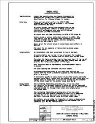
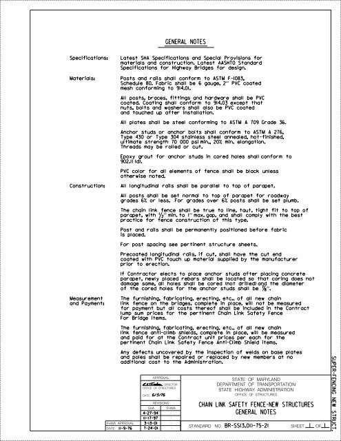
GENERAL NOTESSpecifications:Latest SHA Specifications and Special Provisions formaterials and construction. Latest AASHTO StandardSpecifications for Highway Bridges for design.Materials:Posts and rails shall conform to ASTM F-1083,Schedule 80. Fabric shall be 6 gauge, 2’’ PVC coatedmesh conforming to 914.01.All posts, braces, fittings and hardware shall be PVCcoated. Coating shall conform to 914.03 except thatnuts, bolts and washers shall also be PVC coatedand touched up after installation.All plates shall be steel conforming to ASTM A 709 Grade 36.Anchor studs or anchor bolts shall conform to ASTM A 276,Type 430 or Type 304 stainless steel annealed, hot-finished,ultimate strength 70 000 psi min., 20% min. elongation.Threads may be rolled or cut.Epoxy grout for anchor studs in cored holes shall conform to902.11 (d).PVC color for all elements of <strong>fence</strong> shall be black unlessotherwise noted.Construction:All longitudinal rails shall be parallel to top of parapet.All posts shall be set normal to top of parapet for roadwaygrades 6% or less. For grades over 6% posts shall be set plumb.The <strong>chain</strong> <strong>link</strong> <strong>fence</strong> shall be true to line, taut, tight fit to top ofparapet, with ’’ min. to 1’’ max. gap, and shall comply with the bestpractice for <strong>fence</strong> construction of this type.Post and rails shall be permanently positioned before fabricis placed.For post spacing see pertinent structure sheets.Precoated longitudinal rails, if cut, shall have the cut endcoated with PVC touch up material supplied by the manufacturerprior to erection.If Contractor elects to place anchor studs after placing concreteparapet, <strong>new</strong>ly placed rebars shall be located so that coring does notdamage same, all holes shall be cored (not drilled) and the diameterof the cored holes for the anchor studs shall be ’’.Measurementand Payment:The furnishing, fabricating, erecting, etc., of all <strong>new</strong> <strong>chain</strong><strong>link</strong> <strong>fence</strong> on the bridges, complete in place, will not be measuredfor payment but all costs thereof shall be included in the Contractlump sum prices for the pertinent Chain Link Safety FenceFor Bridge items.The furnishing, fabricating, erecting, etc., of all <strong>new</strong> <strong>chain</strong><strong>link</strong> <strong>fence</strong> anti-climb shields, complete in place, will be measuredand paid for at the Contract unit prices per each for thepertinent Chain Link Safety Fence Anti-Climb Shield items.Any defects uncovered by the inspection of welds on base platesand poles shall be repaired or replaced by <strong>new</strong> members at noadditional cost to the Administration.FHWA APPROVALDATE: 11-9-76DATE: 6/3/76SHAAPPROVALREVISIONSDIRECTOROFFICE OF STRUCTURES4-27-9411-17-973-13-017-24-01FHWASTATE OF MARYLANDDEPARTMENT OF TRANSPORTATIONSTATE HIGHWAY ADMINISTRATIONOFFICE OF STRUCTURESCHAIN LINK SAFETY FENCE-NEW STRUCTURESGENERAL NOTESSTANDARD NO. BR-SS(3.01)-75-21 SHEET 1 OF 1SUPER-FENCING NEW STRUCT.
GENERAL NOTESSpecifications:Latest SHA Specifications and Special Provisions formaterials and construction. Latest AASHTO LRFDBridge Design Specifications.Materials:Posts and rails shall conform to ASTM F-1083,Schedule 80. Fabric shall be 6 gauge, 2’’ PVC coatedmesh conforming to 914.01.All posts, braces, fittings and hardware shall be PVCcoated. Coating shall conform to 914.03 except thatnuts, bolts and washers shall also be PVC coatedand touched up after installation.All plates shall be steel conforming to ASTM A 709 Grade 36.Anchor studs or anchor bolts shall conform to ASTM A 276,Type 430 or Type 304 stainless steel annealed, hot-finished,ultimate strength 70 000 psi min., 20% min. elongation.Threads may be rolled or cut.Epoxy grout for anchor studs in cored holes shall conform to902.11 (d).PVC color for all elements of <strong>fence</strong> shall be black unlessotherwise noted.Construction:All longitudinal rails shall be parallel to top of parapet.All posts shall be set normal to top of parapet for roadwaygrades 6% or less. For grades over 6% posts shall be set plumb.The <strong>chain</strong> <strong>link</strong> <strong>fence</strong> shall be true to line, taut, tight fit to top ofparapet, with ’’ min. to 1’’ max. gap, and shall comply with the bestpractice for <strong>fence</strong> construction of this type.Post and rails shall be permanently positioned before fabricis placed.For post spacing see pertinent structure sheets.Precoated longitudinal rails, if cut, shall have the cut endcoated with PVC touch up material supplied by the manufacturerprior to erection.If Contractor elects to place anchor studs after placing concreteparapet, <strong>new</strong>ly placed rebars shall be located so that coring does notdamage same, all holes shall be cored (not drilled) and the diameterof the cored holes for the anchor studs shall be ’’.Measurementand Payment:The furnishing, fabricating, erecting, etc., of all <strong>new</strong> <strong>chain</strong><strong>link</strong> <strong>fence</strong> on the bridges, complete in place, will not be measuredfor payment but all costs thereof shall be included in the Contractlump sum prices for the pertinent Chain Link Safety FenceFor Bridge items.The furnishing, fabricating, erecting, etc., of all <strong>new</strong> <strong>chain</strong><strong>link</strong> <strong>fence</strong> anti-climb shields, complete in place, will be measuredand paid for at the Contract unit prices per each for thepertinent Chain Link Safety Fence Anti-Climb Shield items.Any defects uncovered by the inspection of welds on base platesand poles shall be repaired or replaced by <strong>new</strong> members at noadditional cost to the Administration.FHWA APPROVALDATE: 11-9-76DATE: 6/3/76SHAAPPROVALREVISIONSDIRECTOROFFICE OF STRUCTURES11-17-973-13-017-24-0110-9-07FHWASTATE OF MARYLANDDEPARTMENT OF TRANSPORTATIONSTATE HIGHWAY ADMINISTRATIONOFFICE OF STRUCTURESCHAIN LINK SAFETY FENCE-NEW STRUCTURESGENERAL NOTESVERIF IED10-9-2007LR DSTANDARD NO. BR-SS(3.01)-75-21(L) SHEET 1 OF 1FSUPER-FENCING NEW STRUCT.
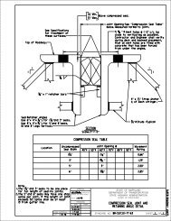
Cap2’’2’Cap1.660’’ O.D. pipe, weighing 3.00 #/ft.(Typical all longitudinal rails).Weld additional straight post (showndashed) onto curved post at lastfull height post on bridge typicalboth ends, both sides.2’-8’ R.1’-7 ’’2’-6 ’’2.875’’ O.D. pipe, weighing 7.66 #/ft.(Typical all posts).6’-2 ’’2’’-#6 gauge <strong>chain</strong> <strong>link</strong><strong>fence</strong> screen (7’-0’’).Typ.3’-3’’ ’’plate-see DETAIL A1 ’’3’’Note:Straight back parapet shown,see Typical Section for exactconfiguration.9’’7 ’’2’-3’’Varies 4’’ 2 ’’4- ’’ anchor studswith nuts and washershex. head anchor bolt(head down) with hex.nuts and washers.*7’’3 ’’ 3 ’’4 ’’ 1 ’’c anchor studs or bolts.5’’ 2’’7’’ x 7’’ x ’’ P1 ’’Front faceparapet attop.2.875’’ O.D. Post3’-0’’ and greatersidewalk.TYPICAL SECTIONScale: ’’=1’-0’’Roadway1 ’’1’’ 4’’ 1’’7’’DETAIL AScale: 1’’ =1’-0’’Note:Type I Fence shall only be usedadjacent to sidewalks 3’-0’’ orgreater.1 ’’ hole in plate.DIRECTOROFFICE OF STRUCTURES*As an option, the Contractor may set theanchor studs after placing concrete barrierusing ’’ dia. cored holes and an approvedepoxy grout. Nuts and washers shall be omittedfrom the embedded ends of anchor studs. Noadditional compensation will be allowed for thisoption.STATE OF MARYLANDDEPARTMENT OF TRANSPORTATIONSTATE HIGHWAY ADMINISTRATIONOFFICE OF STRUCTURESTYPE CHAIN LINK SAFETY FENCENEW STRUCTURESSTANDARD SHEET 1 OF 3SUPER-FENCING NEW STRUCT.
Cap (Typicalall posts).Single # 9 gauge or double # 13 gaugectie wires @ 2’-0’’ /c .Typical bottomtwo Longitudinal Rails; @ 1’-6’’ for toptwo Longitudinal Rails (minimum of 2 turns).Expansion Joint. (Typical allLongitudinal Rails at expansionjoints in bridges).APPROVALDATE: 6/8/76REVISIONSSHA FHWAWeighing 3.00 #/ft.(Typical).2.875’’ O.D. Post Weighing7.66 #/ft.(Typical).STATE OF MARYLANDDEPARTMENT OF TRANSPORTATIONSTATE HIGHWAY ADMINISTRATIONSTANDARD NO. BR-SS(3.02)-75-22SHEET 2 OF 3+ -c /cELEVATIONFHWA APPROVALDATE: 11-9-76DIRECTOROFFICE OF STRUCTURES1-1-886-8-9011-17-971-22-011.66’’ O.D. Longitudinal RailOFFICE OF STRUCTURESTYPE CHAIN LINK SAFETY FENCENEW STRUCTURESFabric to be ’’ min. to 1’’max. clear of top of parapet.Expansion Joint in Parapet.Scale: ’’=1’-0’’*Before placing fencing, place ’’ to 1’’ thickmaterial (wood, etc.) on top of parapet to ensurethe desired gap is achieved. After <strong>fence</strong> is rigidlyattached, this temporary blocking shall be removed.*Single # 9 gauge or double # 13gauge tie wires (see sheet 1 of 3for exact location). Typical each post.SUPER-FENCING NEW STRUCT.
Anti-climb Shield (shown dashed). PlaceAnti-climb Shield at first fullheight post. Typical for both endsand both sides of each bridge.APPROVALDIRECTOROFFICE OF STRUCTURESDATE: 6/19/89REVISIONSSHA FHWA11-17-977-31-98FHWA APPROVAL1-22-01DATE: 6-8-909-22-061’-9’’1’-0’’Typ.Stretcher BarAttachment ’’ x ’’Stretcher BarAttach to straight postAttach to curved post.Cap (Typicalall posts)1’-0’’Typ.Stretcher BarAttachment ’’ x ’’StretcherBar ’’ Truss RodSTATE OF MARYLANDDEPARTMENT OF TRANSPORTATIONSTATE HIGHWAY ADMINISTRATIONOFFICE OF STRUCTURESTYPE CHAIN LINK SAFETY FENCENEW STRUCTURESSTANDARD NO. BR-SS(3.02)-75-22SHEET 3 OF 3**4 ’’*Post SpacingPost Spacing*Post SpacingEND SECTION DETAILScale: ’’=1’-0’’****See plans for <strong>fence</strong>post spacing.Dimension is 1’-0’’when first <strong>fence</strong> postis on the bridge.SUPER-FENCING NEW STRUCT.
Cap2’’1.660’’ O.D. pipe, weighing 3.00 #/ft.(Typical all longitudinal rails).2.875’’ O.D. pipe, weighing 7.66 #/ft.(Typical all posts).Typ.5’-0 ’’2’’-#6 gauge <strong>chain</strong> <strong>link</strong><strong>fence</strong> screen (5’-0’’).’’ plate-see DETAIL A9’’3’’Note:34’’ F-shape parapet withstraight back shown, seeTypical Section for exactparapet configuration.Varies(head down) with hex. nuts and washers.*canchor studs or bolts.P1 ’’5’’ 2’’1’’TYPICAL SECTIONFront face ofScale: ’’=1’-0’’parapet at top.7’’2.875’’ O.D. Post*As an option, the Contractor may set theanchor studs after placing concrete barrierusing ’’ dia. cored holes and an approvedepoxy grout. Nuts and washers shall be omittedfrom the embedded ends of anchor studs. No1 ’’7’’DETAIL AScale: 1’’=1’-0’’11-9-76DIRECTOROFFICE OF STRUCTURES3-22-88 6-8-9011-17-973-21-016-1-05additional compensation will be allowed for thisoption.STATE OF MARYLANDDEPARTMENT OF TRANSPORTATIONSTATE HIGHWAY ADMINISTRATIONOFFICE OF STRUCTURESTYPE I I CHAIN LINK SAFETY FENCEFOR NEW STRUCTURESWITH 34’’ OR 42’’ F-SHAPE PARAPETSTANDARD BR-SS(3.03)-05-23SHEET 1OF 3SUPER-FENCING NEW STRUCT.
Cap (Typicalall posts).FHWA APPROVALDATE: 11-9-76Single # 9 gauge or double # 13 gaugetie wires @ 2’-0’’ .Typical eachLongitudinal Rail (minimum of 2 turns).For End SectionDetails see Sheet3 of 3.1.66’’ O.D. Longitudinal RailAPPROVALDIRECTOROFFICE OF STRUCTURESDATE: 6/8/76REVISIONSSHA FHWA3-22-88 6-8-9011-17-973-21-016-1-05Weighing 3.00 #/ft. (Typical).2.875’’ O.D. Post Weighing7.66 #/ft. (Typical).Expansion Joint. (Typical allLongitudinal Rails at expansionjoint in bridges). ’’ x ’’StretcherBar ’’ x 1’’ Brace Band with ’’ x 1 ’’ Carriage Bolt& Nut (typical).1’-0’’Typ. ’’ Truss RodSTATE OF MARYLANDDEPARTMENT OF TRANSPORTATIONSTATE HIGHWAY ADMINISTRATIONOFFICE OF STRUCTURESTYPE I I CHAIN LINK SAFETY FENCEFOR NEW STRUCTURESWITH 34’’ OR 42’’ F-SHAPE PARAPETSTANDARD NO. BR-SS(3.03)-05-23SHEET 2 OF 3+-c /cELEVATIONFabric to be ’’ min. to 1’’max. clear of top of parapet.Expansion Joint in Parapet.Scale: ’’=1’-0’’*Before placing fencing, place ’’ to 1’’ thickmaterial (wood, etc.) on top of parapet to ensurethe desired gap is achieved. After <strong>fence</strong> is rigidlyattached, this temporary blocking shall be removed.*Single # 9 gauge or double # 13gauge tie wires (see sheet 1 of 3for exact location). Typical each post.SUPER-FENCING NEW STRUCT.
FHWA APPROVALDATE: 6-8-90Stretcher Barheight post. Typical for both endsand both sides of each bridge.Cap (Typicalall posts).APPROVALDATE: 6/19/89REVISIONSSHA FHWAAttachment ’’ x ’’ StretcherBarAnti-climb Shield (shown dashed). PlaceAnti-climb Shield at first full ’’ x ’’ StretcherBarSTATE OF MARYLANDDEPARTMENT OF TRANSPORTATIONSTATE HIGHWAY ADMINISTRATIONSTANDARD NO. BR-SS(3.03)-05-23SHEET 3 OF 31’-3’’9’’1’-0’’Typ.DIRECTOROFFICE OF STRUCTURES11-17-976-1-05OFFICE OF STRUCTURESTYPE I I CHAIN LINK SAFETY FENCEFOR NEW STRUCTURESWITH 34’’ OR 42’’ F-SHAPE PARAPET*Post Spacing**4 ’’* *Post SpacingEND SECTION DETAILScale: ’’=1’-0’’Post Spacing****Post SpacingSee plans for <strong>fence</strong>post spacing.Dimension is 1’-0’’when first <strong>fence</strong> postis on the bridge.SUPER-FENCING NEW STRUCT.
Drill 0.250’’ hole fitting and 0.221’’ hole(#2 drill) in rail for 1-#14 x ’’ Type U RoundHead Steel Drive Screw zinc plated. (Typ. eachfitting on either side of expansion joint).1.660’’ O.D. Rail 3.00 #/ft. 1.050’’ O.D. Sleeve 1.47 #/ft.Low SideHigh Side*6’’2’’6’’EXPANSION JOINT DETAILSScale: 1’’= 1’-0’’1’’ x ’’ plate, weldedto post.cL PostcL ’’ x 1’’ carriage boltand nut (not shown).Malleable iron fitting. ’1’’ x ’’ plate, weldedto post.Typ.cL ’’ x 1’’ carriagebolt and nut(not shown). ’cL PostcL Longitudinal RailcL Longitudinal RailTyp.Note: Screen not shown.END POSTINTERMEDIATE POSTMalleable iron fitting.TOP LONGITUDINAL RAIL - POST ATTACHMENTScale: 1’’= 1’-0’’’’ Truss rods, end <strong>fence</strong> panels only.1’’ max.Main <strong>fence</strong> post or framepost for anti-climb shield.Jam Nut’’ clipMalleable ironturnbuckle.Hex. nutthreads shallbe ’’-18 rolled or’’-16 cut.’’ x ’’ Stretcher Bar’’ x 1’’ BraceBandMalleable iron fitting.cL ’’ x 1’’ carriagebolt and nut.STRETCHER BAR ATTACHMENTScale: NoneTRUSS ROD ATTACHMENTScale: 1’’= 1’-0’’*If opening in parapet is 2’’ or less. Ifopening is greater then this, dimensionshall be increased to match proposedmovement.FHWA APPROVALDATE: 11-9-76APPROVALDIRECTOROFFICE OF STRUCTURESDATE: 6/3/76REVISIONSSHA FHWA8-4-87 6-8-901-22-01STATE OF MARYLANDDEPARTMENT OF TRANSPORTATIONSTATE HIGHWAY ADMINISTRATIONOFFICE OF STRUCTURESCHAIN LINK SAFETY FENCE - NEW STRUCTURESMISCELLANEOUS DETAILSSTANDARD NO. BR-SS(3.04)-75-24SHEET 1 OF 1SUPER-FENCING NEW STRUCT.
cL of PostcL of Pipe2’-9’’cL of Top Rail1.660’’ O.D. pipe,weighing 3.00 #/ft.’’ x ’’4’-9 ’’Stretcher Bar2’’-#6 gauge <strong>chain</strong><strong>link</strong> <strong>fence</strong> screen.Attach Anti-climb shield to<strong>fence</strong> post by small sectionsof pipe to each vertical postwith fillet weld.Pipe connector to be shapedto have full contact witheach post.4’-8’’Stretcher BarAttachment (Typ.)spaced as shown.’’ plate-see DETAIL BTop of ParapetBAcL of Bottom RailBwith hex. nuts and washers’’ anchor stud withhex. nut and washer(@ each end) or ’’hex. head anchor bolt(head down) with hex.nut and washer.*hex. head anchor bolt(head down) with hex.nuts and washers.F-Shape Parapet*Vertical Parapet*As an option, the Contractor may set theanchor studs after placing concrete barrierusing ’’ dia. cored holes and an approvedepoxy grout. Nuts and washers shall be omittedfrom the embedded ends of anchor studs. Noadditional compensation will be allowed for thisoption.Note:For Sections A-A and B-B see Sheet2 of 2 of this standard.FHWA APPROVALDATE: 10-3-80DATE:SHA1-11-883-13-017-26-019-2-03APPROVAL6/3/76REVISIONSDIRECTOROFFICE OF STRUCTURESFHWA6-8-90Note:TYPICAL SECTIONScale: ’’= 1’-0’’Straight back parapet shown, see TypicalSection for exact configuration.STATE OF MARYLANDDEPARTMENT OF TRANSPORTATIONSTATE HIGHWAY ADMINISTRATIONOFFICE OF STRUCTURESANTI-CLIMB SHIELD FORCHAIN LINK SAFETY FENCES TYPES I AND I ISTANDARD NO. BR-SS(3.05)-75-25SHEET 1 OF 2SUPER-FENCING NEW STRUCT.
APPROVALDIRECTOROFFICE OF STRUCTURESDATE:6/3/76REVISIONSFHWA APPROVALDATE: 10-3-80SHA8-3-841-11-883-21-01FHWA11-8-846-8-90NO. BR-SS(3.05)-75-25
Transition Area(typ.)c c cAbutmentPierJoint (typ.)Pier* b b a a a a** **FHWA APPROVALDATE: 12-19-79APPROVALDIRECTOROFFICE OF STRUCTURESDATE: 7/26/79REVISIONSSHA FHWA3-7-833-15-836-1-05* 2b = average spacing of endpost and adjacent span, withexceptions as noted on Sheet 2.STANDARDELEVATION - FENCINGScale: None**2a = average spacingof flanking spans.FOR OFFICE USE ONLYSTATE OF MARYLANDDEPARTMENT OF TRANSPORTATIONSTATE HIGHWAY ADMINISTRATIONOFFICE OF STRUCTURESLAYOUT OF FENCING ON BRIDGESNO. BR-SS(3.06)-03-78SHEET 1 OF 2FENCE SPACING ON BRIDGESAll spacings shall be equal in each span, and on each transition area of each end post.Fence post spacing should range from 6’-0’’ min. to 8’-0’’ max. except as modified in thetransition area described on Sheet 2. Effort should be made to make spacing of postsfor all spans nearly equal as possible.Transition areas shall be provided on both ends of the bridge comprised of a taperedconcrete lug and three <strong>fence</strong> panels, all equally spaced as shown on Sheet 2 of 2.Fence shall be continuous across all supports.This layout applies to 34’’ F-shape parapets, 42’’ F-shape parapets, and parapets withsidewalks.SUPER-FENCING NEW STRUCT.
4 equal spaces on transitioncJointEnd ofend postc Post*bb1’-0’’ joint location A4’’ all other joint locationsTop ofRoadway A B C D E2’-8’’**Bridge Expansion JointEnd PostBridgeELEVATION - END POST TRANSITION AREA*2b = average spacing of endpost and adjacent span, withexceptions stated in Note 4.Scale: NoneNotes:1. Transition areas should be provided on both ends of the bridge, comprised of a tapered concrete lugand three tapered <strong>fence</strong> panels, all equally spaced.2. The end of the concrete lug on both the approach and trail end shall be 2’-8’’.3. The End Post Transition Area shall always begin at the end of the end post and be laid out in accordancewith the following chart.4. When roadway joint falls in the middle of a tapered panel (Joint Locations B, C, and D) the first full heightpanel on the bridge shall be the average spacing of the panels in the transition area and the adjacentspan.END POST TRANSITION AREARoadwayJointLocationEnd Post LengthFence TransitionPanels on End PostFence TransitionPanels on BridgeAL < 8’-0’’03B8’-0’’ < L < 12’-0’’2C12’-0’’ < L < 20’-0’’11D20’-0’’ < L < 28’-0’’2**E28’-0’’ < L3 + (n + ) fullheight panels0**Location of Bridge Expansion Joint E varies depending on thenumber of full height panels on the endpost.n = the number of full heightpanels on the end postFHWA APPROVALDATE:APPROVALDIRECTOROFFICE OF STRUCTURESDATE: 6/1/05REVISIONSSHA FHWASTANDARDFOR OFFICE USE ONLYSTATE OF MARYLANDDEPARTMENT OF TRANSPORTATIONSTATE HIGHWAY ADMINISTRATIONOFFICE OF STRUCTURESLAYOUT OF FENCING ON BRIDGESNO. BR-SS(3.06)-03-78SHEET 2 OF 2SUPER-FENCING NEW STRUCT.
GENERAL NOTESSpecifications:Latest SHA Specifications and Special Provisions formaterials and construction. Latest AASHTO StandardSpecifications for Highway Bridges for design.Materials:Posts and rails shall conform to ASTM F-1083,Schedule 80. Fabric shall be 6 gauge, 2’’ PVC coatedmesh conforming to 914.01.All posts, braces, fittings and hardware shall be PVCcoated. Coating shall conform to 914.03 except thatnuts, bolts and washers shall also be PVC coatedand touched up after installation.All plates shall be steel conforming to ASTM A 709 Grade 36.Anchor studs or anchor bolts shall conform to ASTM A 276,Type 430 or Type 304 stainless steel annealed, hot-finished,ultimate strength 70 000 psi min., 20% min. elongation.Threads may be rolled or cut.Epoxy grout for anchor studs in cored holes shall conform to902.11 (d).PVC color for all elements of <strong>fence</strong> shall be black unlessotherwise noted.Construction:All longitudinal rails shall be parallel to top of wall.All posts shall be set normal to top of wall for roadwaygrades 6% or less. For grades over 6% posts shall be set plumb.The <strong>chain</strong> <strong>link</strong> <strong>fence</strong> shall be true to line, taut, tight fit to top ofwall (’’ maximum gap) and shall comply with the best practicefor <strong>fence</strong> construction of this type.Post and rails shall be permanently positioned before fabricis placed.For post spacing see pertinent structure sheets.Precoated longitudinal rails, if cut, shall have the cut endcoated with PVC touch up material supplied by the manufacturerprior to erection.If Contractor elects to place anchor studs after placing concretewall, <strong>new</strong>ly placed rebars shall be located so that coring does notdamage same, all holes shall be cored (not drilled) and the diameterof the cored holes for the anchor studs shall be ’’.Measurementand Payment:The furnishing, fabricating, erecting, etc., of all <strong>new</strong> <strong>chain</strong><strong>link</strong> <strong>fence</strong> on the retaining wall or culvert headwalls and wing walls,complete in place, will not be measured for payment but all coststhereof shall be included in the Contract lump sum prices for thepertinent Retaining Wall or Box Culvert item(s).Any defects uncovered by the inspection of welds on base platesand poles shall be repaired or replaced by <strong>new</strong> members at noadditional cost to the Administration.FHWA APPROVALDATE:APPROVALDIRECTOROFFICE OF STRUCTURESDATE: 11/6/96REVISIONSSHA FHWA3-13-017-24-01STATE OF MARYLANDDEPARTMENT OF TRANSPORTATIONSTATE HIGHWAY ADMINISTRATIONOFFICE OF STRUCTURESCHAIN LINK SAFETY FENCERETAINING WALLS AND BOX CULVERTSGENERAL NOTESSTANDARD NO. BR-SS(3.11)-96-317SHEET 1 OF 1SUPER-FENCING NEW STRUCT.
Cap1.660’’ O.D. pipe, weighing 3.00 #/ft.(Typical all longitudinal rails).2.875’’ O.D. pipe, weighing 7.66 #/ft.(Typical all posts).Typ.3’-0 ’’2’’2’’-#6 gauge <strong>chain</strong> <strong>link</strong><strong>fence</strong> screen (3’-0’’).’’ plate-see DETAIL A9’’3’’1 ’’7 ’’2- ’’ anchor studs with nuts and washers*Top of finishedground4’’TYPICAL SECTIONScale: ’’ = 1’-0’’c’’ holes for ’’ anchorstuds or bolts.*As an option, the Contractor may set theanchor studs after placing concrete wall7’’3 ’’3 ’’1 ’’4 ’’4’’ x 7’’ x ’’ P2’’ 2’’ 1’’Front face ofwall at top.2.875’’ O.D. Postusing ’’ dia. cored holes and an approvedepoxy grout. Nuts and washers shall be omittedfrom the embedded ends of anchor studs. Noadditional compensation will be allowed for thisoption.1 ’’4’’DETAIL AScale: 1’’ = 1’-0’’FHWA APPROVALDATE:1 ’’ hole in plate.DATE: 11/6/96SHA3-13-01APPROVALREVISIONSDIRECTOROFFICE OF STRUCTURES3-31-10FHWANote:This <strong>fence</strong> shall be used onbox culverts with headwallslocated at the bottom of fillslopes.STATE OF MARYLANDDEPARTMENT OF TRANSPORTATIONSTATE HIGHWAY ADMINISTRATIONOFFICE OF STRUCTURESTYPE CHAIN LINK SAFETY FENCERETAINING WALLS AND BOX CULVERTSSTANDARD NO. BR-SS(3.12)-96-318SHEET 1 OF 2SUPER-FENCING NEW STRUCT.
Stretcher BarAttachmentSingle #9 gauge or double #13 gaugetie wires @ 2’-0’’ + - c/c.Typical eachCap (Typicallongitudinal rail (minimum of 2 turns).all posts).1’-0’’Typ.’’ x ’’ StretcherBar’’ x 1’’ Brace band with’’ x 1’’ carriage bolt& nut (typical).1.66’’ O.D. longitudinal railweighing 3.00 #/ft. (Typical).2.875’’ O.D. post weighing7.66 #/ft. (Typical).1’-0’’ Fabric to be ’’ +-clear of top of wall.Top of finishedgroundSingle #9 gauge or double #13gauge tie wires (see sheet 1 of 2for exact location). Typical each post.ELEVATIONScale: ’’ = 1’-0’’Note:For additional details see Std. No.BR-SS(3.04)-75-24.FHWA APPROVALDATE:APPROVALDIRECTOROFFICE OF STRUCTURESDATE: 11/6/96REVISIONSSHA FHWA3-31-10STATE OF MARYLANDDEPARTMENT OF TRANSPORTATIONSTATE HIGHWAY ADMINISTRATIONOFFICE OF STRUCTURESTYPE CHAIN LINK SAFETY FENCERETAINING WALLS AND BOX CULVERTSSTANDARD NO. BR-SS(3.12)-96-318SHEET 2 OF 2SUPER-FENCING NEW STRUCT.
(typ.)c AbutmentJoint (typ.)c cPier Pier1’-0’’* b b a a a a** **Transition AreaFHWA APPROVALDATE:APPROVALDIRECTOROFFICE OF STRUCTURESDATE: 6/1/05REVISIONSSHA FHWA* 2b = average spacing of endpost and adjacent span.** 2a = average spacingof flanking spans.STANDARDELEVATION - RAILINGScale: NoneFOR OFFICE USE ONLYSTATE OF MARYLANDDEPARTMENT OF TRANSPORTATIONSTATE HIGHWAY ADMINISTRATIONOFFICE OF STRUCTURESLAYOUT OF RAILING ON BRIDGESNO. BR-SS(3.13)-05-374SHEET 1 OF 2POST SPACING ON BRIDGES WITH ONE OR TWO STRAND RAILINGAll spacings shall be equal in each span, and on each end post.Rail post spacing should range from 6’-0’’ min. to 8’-0’’ max. unless a closer post spacingis required due to crash test and as modified in the transition area described on Sheet 2.Effort should be made to make spacing of posts for all spans as nearly equal as possible.Transition areas shall be provided on both ends of the bridge comprised of a taperedconcrete lug as shown on Sheet 2 of 2.Rail shall be continuous across all supports.SUPER-FENCING NEW STRUCT.
End ofend postEqual spaces lug and railspacing on end post.c PostcJoint1’-0’’*bbTop ofRoadway A B C2’-8’’**Bridge Expansion JointEnd PostBridge*2b = average spacing of endpost and adjacent span.ELEVATION - END POST TRANSITION AREAScale: NoneNotes:1. Transition areas should be provided on both ends of the bridge, comprised of a tapered concrete lug.2. Transition areas will always begin at the end of the end posts and be laid out in accordance withthe following chart.3.All rail spaces shall be equal in each span.END POST TRANSITION AREARoadwayJointLocationAEnd Post LengthL < 8’-0’’Rail Panelson End Post0B8’-0’’ < L < 12’-0’’**C20’-0’’ < L(n + ) fullrail panel**Location of Bridge Expansion Joint C varies depending onthe number of full height rail panels on the endpost.n = the number of full railpanels on the end postFHWA APPROVALDATE:APPROVALDIRECTOROFFICE OF STRUCTURESDATE: 6/1/05REVISIONSSHA FHWASTANDARDFOR OFFICE USE ONLYSTATE OF MARYLANDDEPARTMENT OF TRANSPORTATIONSTATE HIGHWAY ADMINISTRATIONOFFICE OF STRUCTURESLAYOUT OF RAILING ON BRIDGESNO. BR-SS(3.13)-05-374SHEET 2 OF 2SUPER-FENCING NEW STRUCT.