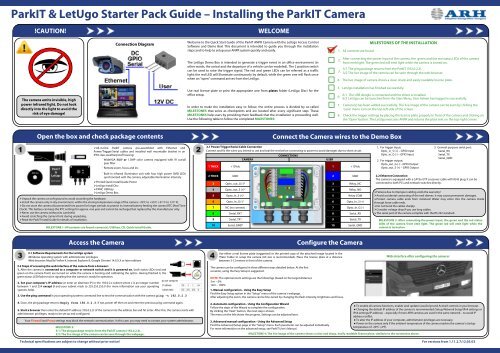
ParkIT & LetUgo Starter Pack Guide â Installing the ParkIT Camera
ParkIT & LetUgo Starter Pack Guide â Installing the ParkIT Camera
ParkIT & LetUgo Starter Pack Guide â Installing the ParkIT Camera

You also want an ePaper? Increase the reach of your titles
YUMPU automatically turns print PDFs into web optimized ePapers that Google loves.
<strong>ParkIT</strong> & <strong>LetUgo</strong> <strong>Starter</strong> <strong>Pack</strong> <strong>Guide</strong> – <strong>Installing</strong> <strong>the</strong> <strong>ParkIT</strong> <strong>Camera</strong>!CAUTION!WELCOMEConnection DiagramWelcome to <strong>the</strong> Quick Start <strong>Guide</strong> of <strong>the</strong> <strong>ParkIT</strong> ANPR <strong>Camera</strong> with <strong>the</strong> <strong>LetUgo</strong> Access ControlSoftware and Demo Box! This document is intended to guide you through <strong>the</strong> installationsteps and to help to setup your ANPR system quickly and easily.The <strong>LetUgo</strong> Demo Box is intended to generate a trigger event in an office environment (ino<strong>the</strong>r words, <strong>the</strong> arrival and <strong>the</strong> departure of a vehicle can be modeled). The 2 position switchcan be used to raise <strong>the</strong> trigger signal. The red and green LEDs can be referred as a trafficlight: <strong>the</strong> red LED will illuminate continuously by default, while <strong>the</strong> green one will flash oncewhen an "open" command arrives from <strong>the</strong> <strong>LetUgo</strong>.1. All contents are found.2.3.4.MILESTONES OF THE INSTALLATIONAfter connecting <strong>the</strong> power input of <strong>the</strong> camera, <strong>the</strong> green and <strong>the</strong> red status LEDs of <strong>the</strong> camerafront emit light. The green led will emit light while <strong>the</strong> camera is turned on.3/1 The ping package returns from <strong>the</strong> <strong>ParkIT</strong> (192.0.2.3).3/2 The live image of <strong>the</strong> camera can be seen through <strong>the</strong> web browser.The live image of camera shows a clear, sharp and easily readable license plate.The camera emits invisible, highpower infrared light. Do not lookdirectly into <strong>the</strong> light to avoid <strong>the</strong>risk of eye damage!Use real license plate or print <strong>the</strong> appropriate one from plates folder (<strong>LetUgo</strong> Disc) for <strong>the</strong>office setup.In order to make <strong>the</strong> installation easy to follow, <strong>the</strong> entire process is divided by so-calledMILESTONES that serve as checkpoints and are located after every significant step. TheseMILESTONES help users by providing <strong>the</strong>m feedback that <strong>the</strong> installation is proceeding well.Use <strong>the</strong> following table to follow <strong>the</strong> completed MILESTONES:5. <strong>LetUgo</strong> installation has finished successfully.6.7.6/1 The USB dongle is connected and <strong>the</strong> driver is installed.6/2 <strong>LetUgo</strong> can be launched from <strong>the</strong> Start Menu. User Admin has logged in successfully.<strong>Camera</strong>(s) has been added successfully. The live image of <strong>the</strong> camera can be seen by clicking <strong>the</strong>‘Lane’ menu icon on <strong>the</strong> top-left side of <strong>the</strong> screen.8. Check <strong>the</strong> trigger settings by placing <strong>the</strong> license plate properly in front of <strong>the</strong> camera and clicking on<strong>the</strong> ‘Open’ button. The <strong>LetUgo</strong> executes ANPR and returns <strong>the</strong> plate text on <strong>the</strong> top-right corner.Open <strong>the</strong> box and check package contentsConnect <strong>the</strong> <strong>Camera</strong> wires to <strong>the</strong> Demo Box‣All-in-One <strong>ParkIT</strong> camera pre-assembled with E<strong>the</strong>rnet andPower/Trigger/Serial cables and installed wall mountable bracket in anIP65 class wea<strong>the</strong>rproof housing:•WideVGA B&W or 1.3MP color camera equipped with IR cut/allpass filter•Remote zoom, focus and iris•Built-in infrared illuminator unit with four high power SMD LEDssynchronized with <strong>the</strong> camera, adjustable illumination intensity‣Printed Quick Install <strong>Guide</strong> Poster‣<strong>LetUgo</strong> Install Disc‣FXMC USB key‣<strong>LetUgo</strong> Demo Box‣Unpack <strong>the</strong> camera on soft ground to avoid scratching <strong>the</strong> hardware.‣Install <strong>the</strong> camera only in dry environment, within <strong>the</strong> storing temperature range of <strong>the</strong> camera: -35ºC to +55ºC (-31º F to 131º F).‣Do not store <strong>the</strong> camera disconnected from power for longer periods to protect its internal battery feeding <strong>the</strong> camera RTC (Real TimeClock). This battery can keep <strong>the</strong> RTC settings for approx. one year and cannot be recharged but replaced by <strong>the</strong> manufacturer only.‣Never use <strong>the</strong> camera without its sunshield.‣Avoid scratching <strong>the</strong> camera front during unpacking.‣Read <strong>the</strong> <strong>ParkIT</strong> Install <strong>Guide</strong> for details of installation.MILESTONE 1: All contents are found: camera(s), USB key, CD, Quick Install <strong>Guide</strong>.Access <strong>the</strong> <strong>Camera</strong>2.1 Power/Trigger/Serial Cable ConnectionConnect and fix <strong>the</strong> wires you intend to use and seal <strong>the</strong> rest before connecting to power to avoid damages due to short circuit.1 THICK2 THICK45678910+12VdcGNDOpto_out_S (+) 2Opto_in_S (+) 1Opto_in_G (-) 1NC (no connect)Serial_RX 3Serial_TX 3Serial_GND 3CAMERACONNECTIONS3 Opto_out_G (-) 23Relay_NCUSERSerial_GNDConfigure <strong>the</strong> <strong>Camera</strong>1245678910+12VdcGNDRelay_NORelay-COMOpto_In_S (+)Opto_In_G (-)Serial_RXSerial_TX1. For trigger input:Opto_in_S (+) – GPIO InputOpto_in_G (-) – GPIO Input2. For trigger output:Opto_out_G (-) – GPIO OutputOpto_out_S (+) – GPIO Output3. General-purpose serial port:Serial_RXSerial_TXSerial_GND.2.2 E<strong>the</strong>rnet ConnectionThe camera is equipped with a CAT5e UTP crossover cable with RJ45 plug. It can beconnected to both PCs and network switches directly.‣Failures due to improper cabling voids <strong>the</strong> warranty!‣Avoid accidental contacting of <strong>the</strong> end sleeves. It may cause permanent damages.‣Protect camera cable ends from moisture! Water may enter into <strong>the</strong> camera insidethrough loose cable ends.‣Do not bend <strong>the</strong> cables sharply.‣Consider voltage drop if you use long cables.‣The serial port of <strong>the</strong> camera complies with <strong>the</strong> RS 232 standard.MILESTONE 2: After connecting <strong>the</strong> power input, <strong>the</strong> green and <strong>the</strong> red statusLEDs of <strong>the</strong> camera front emit light. The green led will emit light while <strong>the</strong>camera is turned on.3.1 Software Requirements for <strong>the</strong> <strong>LetUgo</strong> system•Windows operating system with administrator privileges•Web browser: Mozilla Firefox 4, Internet Explorer 8, Google Chrome 14.X.X.X or later editions3.2 Steps of accessing <strong>the</strong> web interface of <strong>the</strong> camera from a browser:1. After <strong>the</strong> camera is connected to a computer or network switch and it is powered on, both status LEDs (red andgreen on <strong>the</strong> camera front) are turned on while <strong>the</strong> camera is booting and calibrating <strong>the</strong> optics. Having finished it, <strong>the</strong>green status LED flashes twice signaling that <strong>the</strong> camera is ready for operation.2. Set your computer’s IP address (or enter an alternate IP) in <strong>the</strong> 192.0.2.x subnet where x is an integer numberbetween 1 and 254 except 3 and your subnet mask to 255.255.255.0 (for more information use your operatingsystems help).3. Use <strong>the</strong> ping command in your operating systems command line to test <strong>the</strong> communication with <strong>the</strong> camera: ping -t 192.0.2.34. Soon, <strong>the</strong> ping package returns: Reply from 192.0.2.3. If not, power off <strong>the</strong>n on and enter <strong>the</strong> previous ping command again.5. Start a browser <strong>the</strong>n enter <strong>the</strong> default IP address (192.0.2.3) of <strong>the</strong> camera into <strong>the</strong> address bar and hit enter. After this, <strong>the</strong> camera starts withadministrator privileges, ready to be set up and configured.Your Firewall and Proxy settings may block <strong>the</strong> network communication. In this case, you may need to contact your system administrator.MILESTONE 3:3/1: The ping package returns from <strong>the</strong> <strong>ParkIT</strong> camera (192.0.2.3).3/2: The live image of <strong>the</strong> camera can be seen through <strong>the</strong> webpage.Use ei<strong>the</strong>r a real license plate (suggested) or <strong>the</strong> printed copy of <strong>the</strong> attached image located in <strong>the</strong>‘Plate’ folder to setup <strong>the</strong> camera (A3 size is recommended). Place <strong>the</strong> license plate at a distancebetween 3-12 meters in front of <strong>the</strong> camera.The camera can be configured in three different ways detailed below. At <strong>the</strong> firstoccasion, using <strong>the</strong> Easy Setup is suggested.NOTE: The optimal zoom settings are <strong>the</strong> followings (based on <strong>the</strong> target distance):3 m – 0%12m – 100%1. Manual configuration - Using <strong>the</strong> Easy SetupFind <strong>the</strong> Easy Setup option in <strong>the</strong> “Setup” menu of <strong>the</strong> camera’s webpage.After adjusting <strong>the</strong> zoom, <strong>the</strong> camera can be fine-tuned by changing <strong>the</strong> flash intensity, brightness and focus.2. Automatic configuration - Using <strong>the</strong> Configuration WizardFollow <strong>the</strong> steps of <strong>the</strong> Wizard to complete <strong>the</strong> configuration.By clicking <strong>the</strong> “Next” button, <strong>the</strong> next step is shown.The menu on <strong>the</strong> left shows <strong>the</strong> progress. Settings can be adjusted later.3. Advanced manual configuration - Using <strong>the</strong> Advanced SetupFind <strong>the</strong> Advanced Setup page in <strong>the</strong> “Setup” menu. Each parameter can be adjusted individually.For more information on <strong>the</strong> advanced setup, see <strong>ParkIT</strong> User’s Manual.Web interface after configuring <strong>the</strong> camera:MILESTONE 4: The live image of <strong>the</strong> camera shows a clear and sharp, easily readable license plate, similarly to <strong>the</strong> screenshot above..● To enable all camera functions, enable (and update) JavaScript and ActiveX controls in your browser.● Changing <strong>the</strong> default IP address of <strong>the</strong> camera is recommended (Setup/Network Setup/IPv4 settings orIPv6 settings/IP address) – especially if more ARH cameras are used in <strong>the</strong> same network – to avoid IPaddress conflict.● To alter <strong>the</strong> IP address of your computer, administrator privileges are necessary.● Power on <strong>the</strong> camera only if <strong>the</strong> ambient temperature of <strong>the</strong> camera reaches <strong>the</strong> camera’s startuptemperature of -20ºC (-4ºF).Technical specifications are subject to change without prior notice! For versions from 1.11.2.7;12.05.03
<strong>ParkIT</strong> & <strong>LetUgo</strong> <strong>Starter</strong> <strong>Pack</strong> <strong>Guide</strong> - <strong>Installing</strong> <strong>LetUgo</strong>Access Control FlowchartInstall <strong>the</strong> <strong>LetUgo</strong> Parking Management Software5.1 System requirements• Pentium 4 2GHz CPU or equivalent, 1GB RAM (2GB recommended for Windows7)• Windows XP SP3 or Windows 7 Operating System, HD Ready resolution (1366x768) with minimum 64 MB dedicated videomemory.• 100 Mbit/sec or better LAN connection, E<strong>the</strong>rnet switch for more cameras, 1 USB port (v2.0)• 30GB HDD (approx. 30Mbytes for <strong>the</strong> application, <strong>the</strong> rest is for images, etc.)5.2 Steps of installing <strong>LetUgo</strong>1. The setup program starts automatically after inserting <strong>the</strong> disc (DVD) into <strong>the</strong> optical drive.*2. After clicking [Next], read <strong>the</strong> END-USER LICENSE AGREEMENT. Accept <strong>the</strong> agreement to continue <strong>the</strong> installation by selecting Iaccept <strong>the</strong> agreement and clicking [Next].3. In <strong>the</strong> next step, <strong>the</strong> setup searches for .NET framework on your computer and installs it automatically if it is not available.4. After this, enter <strong>the</strong> license key located on <strong>the</strong> <strong>LetUgo</strong> DVD box. After entering <strong>the</strong> key, click [Next] to view necessary componentsto be installed. Click [Next] again to begin to install <strong>the</strong>se components.5. Select <strong>the</strong> destination folder for <strong>LetUgo</strong> <strong>the</strong>n click [Next].6. Create a desktop icon for <strong>LetUgo</strong> and/or launch it automatically at Windows startup right afterinstallation by ticking <strong>the</strong> corresponding checkboxes.7. Check <strong>the</strong> destination folder before installation <strong>the</strong>n click [Install] to start copying <strong>LetUgo</strong> toyour computer.8. When <strong>the</strong> installation is complete, read <strong>the</strong> <strong>LetUgo</strong> User Manual (View <strong>LetUgo</strong> User’s Manual(pdf) and/or launch <strong>the</strong> application right after <strong>the</strong> installation by checking <strong>the</strong> correspondingcheckboxes.9. Click [Finish] button to finish <strong>the</strong> installation.* If <strong>the</strong> setup program does not start automatically <strong>the</strong>n run INSTALL\<strong>LetUgo</strong>_Setup.exe located on<strong>the</strong> provided Install DVD.● To install <strong>LetUgo</strong>, administrator privileges are necessary.● The license key is valid only with <strong>the</strong> USB dongle purchased for <strong>the</strong> software!● The installer places files into <strong>the</strong> Windows/System32 directory as well. Check your privilegesbefore installing <strong>LetUgo</strong>.● However, <strong>the</strong> application needs only approx. 30 Mbytes of free disk place, at least 30 GBytesavailable free disk space is recommended for saved images, events etc. The required free diskspace highly depends on <strong>the</strong> size and <strong>the</strong> amount of <strong>the</strong> saved images.MILESTONE 5: <strong>LetUgo</strong> installation has finished successfully.Start <strong>LetUgo</strong>Add <strong>the</strong> <strong>ParkIT</strong> <strong>Camera</strong>1. Connect <strong>the</strong> USB dongle intoa free USB port and wait until<strong>the</strong> driver is installed2. Open <strong>the</strong> applicationfrom <strong>the</strong> start menu or byclicking on <strong>the</strong> <strong>LetUgo</strong>desktop icon (if created).3. Enter <strong>the</strong> ‘admin’ Login and ‘admin’Password to begin to use <strong>the</strong> program.At first time, <strong>the</strong> <strong>LetUgo</strong> starts withadministrator privileges.1. By default, no camera is added to <strong>the</strong> system, so <strong>the</strong> Settings/<strong>Camera</strong>s submenuwill appear with a warning massage. In this case click [OK].2. Click [New] and enter <strong>the</strong> data of <strong>the</strong> new camera:NAME: any unique textDIRECTION: Direction of <strong>the</strong> observed lane(s). Note, that in case of ‘undefined’ direction, timespent in cannot be calculated.ADDRESS: IP address of <strong>the</strong> cameraPORT: Port of <strong>the</strong> computer –running <strong>LetUgo</strong>– assigned for communication with <strong>the</strong> camera.TIME OF OPENING: It refers to <strong>the</strong> period of time during which <strong>the</strong> barrier is in opened position.CHECK: The camera can take into account/ignore Permissions and/or Blacklist. Check <strong>the</strong> one(s) tobe taken into account.LOGIN and PASSWORD can be assigned to <strong>the</strong> camera if required. Default: leave it blank.LANESPERMISSIONSREPORTSSETTINGSEXIT.MILESTONE 6:6/1: The USB dongle is connected and <strong>the</strong>driver is installed.6/2: <strong>LetUgo</strong> can be launched from <strong>the</strong> startMenu. User Admin has logged insuccessfully.3. Click [OK] to apply changes.● Filling <strong>the</strong> name and <strong>the</strong> address field is mandatory. Filling <strong>the</strong> o<strong>the</strong>r fields is optional.● For more information on using <strong>LetUgo</strong>, refer to <strong>LetUgo</strong> User’s Manual.MILESTONE 7: <strong>Camera</strong>(s) has been added successfully.The live image of <strong>the</strong> camera can be seen by clicking <strong>the</strong> ‘Lane’ menu icon on <strong>the</strong> top-left side of <strong>the</strong> screen.Check trigger settingsAdd PermissionEnter <strong>the</strong> Event Manager of <strong>the</strong> <strong>Camera</strong> web interface.<strong>LetUgo</strong> sets up trigger and upload configurations necessary for officeenvironment AUTOMATICALLY.The default configurations shown in <strong>the</strong> image are sufficient incase of inductive loop or <strong>LetUgo</strong> Demo Box.To check <strong>the</strong> trigger function click <strong>the</strong> [Configure] button of <strong>the</strong> GPIOTrigger.Start <strong>the</strong> <strong>LetUgo</strong> application and navigate to <strong>the</strong> Permissions menu.The entry and exit is granted for authorized vehicles only. Permissions areassigned to license plates (with exact matching). The system allows entry andexit of <strong>the</strong> successfully identified vehicles with valid permission automaticallyand also creates a log of entry/exit events.New permissions can be added by clicking <strong>the</strong> [NEW] button in <strong>the</strong> Permissionsmenu.To apply <strong>the</strong>se settings click <strong>the</strong> [OK] button. For fur<strong>the</strong>r configurations see <strong>the</strong><strong>LetUgo</strong> User’s Manual.When <strong>the</strong> trigger is active (“vehicle stands on <strong>the</strong> loop”) <strong>the</strong> bulb becomesgreen. O<strong>the</strong>rwise use <strong>the</strong> 2 position switch to raise <strong>the</strong> trigger signal.Plate: Filling <strong>the</strong> number plate text field (without spaces and dashes) isnecessary; filling any o<strong>the</strong>r field is optional. Checking of <strong>the</strong> permission isbased solely on <strong>the</strong> license plate!MILESTONE 8: Check <strong>the</strong> trigger settings by placing <strong>the</strong> license plate properlyin front of <strong>the</strong> camera and clicking on <strong>the</strong> ‘Open’ button. The <strong>LetUgo</strong> executesANPR and returns <strong>the</strong> plate text on <strong>the</strong> top-right corner.Technical specifications are subject to change without prior notice! For versions from 1.11.2.7;12.04.05