Joint Precoding and Predistortion Techniques for Satellite ...
Joint Precoding and Predistortion Techniques for Satellite ...
Joint Precoding and Predistortion Techniques for Satellite ...

You also want an ePaper? Increase the reach of your titles
YUMPU automatically turns print PDFs into web optimized ePapers that Google loves.
<strong>Joint</strong> <strong>Precoding</strong> <strong>and</strong> <strong>Predistortion</strong> <strong>Techniques</strong> <strong>for</strong><strong>Satellite</strong> Telecommunication SystemsMarcos Álvarez-Díaz, Carlos MosqueraDept. of Signal Theory <strong>and</strong> Communications (TSC)University of VigoVigo, Spain{malvarez, mosquera}@gts.tsc.uvigo.esMassimo Neri, Giovanni Emanuele CorazzaDept. of Electronics, Computer Science <strong>and</strong> Systems (DEIS)University of BolognaBologna, Italy{mneri, gecorazza}@deis.unibo.itAbstract— We analyze the application of Tomlinson-Harashimaprecoding to satellite transmission. <strong>Precoding</strong> counteractschannel dispersion at the price of increasing the dynamic rangeof the signal to be transmitted. This conflicts with therequirements of typical satellite transmission, where amplifierswith nonlinear characteristics are used, <strong>and</strong> their incoming signalis desired to present a reduced dynamic range. We proposefractional predistortion as a valid countermeasure against theeffects of the nonlinear amplifier. Simulations allow us to obtainthe per<strong>for</strong>mance of the proposed scheme when applied to twotypical satellite propagation environments <strong>and</strong> compare it to anequivalent scheme using st<strong>and</strong>ard Decision-FeedbackEqualization. We conclude that a system using <strong>Predistortion</strong> ismore sensitive to the effects of satellite transmission-relatednonlinearities than the equivalent DFE system.Keywords— Tomlinson-Harashima precoding; High PowerAmplifliers; Fractional predistortion; Decision-FeedbackEqualization;I. INTRODUCTIONDuring the last years, satellite overlay networks haveshown their ability to deliver multimedia content both to rural<strong>and</strong> urban environment [1]. In the latter case, the adoption ofIntermediate Module Repeaters (IMRs) is in order so as tocomplement the direct path in Non-Line-of-Sight propagationconditions. The introduction of IMRs increases diversity, butinvolves also strong time dispersions, which must be properlytaken into account. In parallel, the wide adoption of precodingtechniques in terrestrial wireline systems has spurred theinterest <strong>for</strong> the application of these techniques to other fieldssuch as Multi-Antenna <strong>and</strong> Multi-User communications [2].<strong>Precoding</strong> offers a means of counteracting channel dispersionwhile allowing an easy combination with channel coding, incontrast with Decision-Feedback Equalization (DFE), wheremore elaborate schemes are needed if channel coding is used.This paper focuses on the application of precodingtechniques to satellite transmission scenarios with dispersivechannels. We consider typical scenarios <strong>for</strong> nomadic users bothin rural <strong>and</strong> urban propagation environment. <strong>Precoding</strong> has theadvantage of counteracting the channel dispersion at thetransmitter side (thus reducing the complexity of the receiver),but increasing the dynamic range of the signal to betransmitted. As precoding technique we choose Tomlinson-Harashima precoding (THP). Due to the large attenuationspresent in satellite transmission, the use of on-board HighPower Amplifiers (HPAs) is m<strong>and</strong>atory. Typical satellite HPAsare Travelling Wave Tube Amplifiers (TWTA), <strong>and</strong> Solid StatePower Amplifiers (SSPAs), both characterized by strong nonlineardistortion in amplitude <strong>and</strong> phase when operating closeto saturation. Hence, the higher dynamic range of the precodedsignal will additionally stimulate the nonlinear behaviour of theHPA. In this paper we evaluate the sensitivity of the precodedsignal to the effects of the HPA, <strong>and</strong> propose a validcountermeasure to this impairment: fractional predistortiontechniques are adopted to precondition the signal entering theHPA, <strong>and</strong> the related benefit is assessed. The results arecompared with the per<strong>for</strong>mance of an alternative setup usingpredistortion at the transmitter side <strong>and</strong> st<strong>and</strong>ard DFE at thereceiver side.The paper is structured as follows. Section II describes thesystems that will be studied throughout the paper. THP <strong>and</strong>fractional predistortion are specifically described in Sections III<strong>and</strong> IV, respectively. In Section V we present <strong>and</strong> discuss theresults of our simulations. Finally, Section VI summarizes themain conclusions of our research <strong>and</strong> points out the relatedfuture lines of research.II. SYSTEM MODELSWe will describe next the two systems which we study inthe present paper: the proposed system using THP <strong>and</strong>predistortion at the transmitter side, <strong>and</strong> the one used <strong>for</strong>comparison, consisting of predistortion at the transmitter <strong>and</strong>DFE in the receiver. The block diagrams of both systems aredepicted in Figure 1.This work has been supported in part by the IST-507052 FP6 SatNExproject. M. Álvarez-Díaz <strong>and</strong> C. Mosquera's work has also been funded by theSpanish MEC project TEC2004-02551.
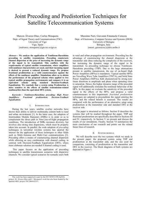
TH PrecoderSourcebits16QAMMapping-ComplexModuloH(z) - 1ShapingFilterPredistorter HPA ChannelAWGNSamplingWhitenedMatchedFilterComplexModuloTH DecoderSlicerDemapperDecided bitsDF EqualizerSource bits16QAMMappingShapingFilterPredistorter HPA ChannelAWGNSamplingWhitenedMatchedFilter-SlicerH(z) - 1DemapperDecided bitsFigure 1. Block diagrams of the systems under study. Top: THP <strong>and</strong> predistortion; bottom: predistortion <strong>and</strong> DFE.A. System with THP <strong>and</strong> predistortionIn our proposed system, the original sequence of bits isconverted into QAM symbols by an appropriate mapper. Thesequence of QAM symbols is then precoded by the THprecoder. The TH precoding operation is described in detail inSection III. The precoded sequence is then converted towave<strong>for</strong>m by a Square Root Raised Cosine filter. Then, thewave<strong>for</strong>m is pre-conditioned by the fractional predistorterbe<strong>for</strong>e being fed into the HPA. Details on fractionalpredistortion are given in Section IV.The output of the HPA is finally sent to the channel. At theend of this section, we give details on the channel models thatwere used during the study. At the output of the channel,complex circular White Gaussian Noise (WGN) is added to<strong>for</strong>m the signal present at the receiver front-end.The Whitened Matched Filter (WMF) is used as thereceiver front end. The WMF is the combination of a filtermatched to the cascade of shaping <strong>and</strong> channel filters, <strong>and</strong> awhitening filter which ensures that the symbol-rate samplednoise component of the received signal is white. The output ofthe WMF is sampled at symbol rate <strong>and</strong> fed into the THdecoder, <strong>for</strong> which details are given in Section III. At theoutput of the TH decoder we have the estimated sequence ofsymbols which is converted to bits by the QAM demapper.B. System with predistortion <strong>and</strong> DFEThe block diagram is depicted in the lower part of Figure 1.It is mostly the same as the THP diagram, except <strong>for</strong> the lack ofTH precoder which is substituted by a DFE block at thereceiver. The feedback filter used in DFE, H(z), is theequivalent minimum-phase response of the whole transmitchannel-receivefilter chain as seen from the receiver after thesymbol rate sampling. The DF equalizer outputs the estimatedsymbol sequence.We consider in this paper both Zero Forcing (ZF-DFE) <strong>and</strong>(unbiased) Minimum Mean Squared Error DFE (MMSE-DFE)[3].C. Channel modelThe considered channel model is a complex tapped delayline that models the transmission through the satellite channel<strong>for</strong> a nomadic used. The considered scenario envisages the useof terrestrial gap fillers, also called Intermediate ModuleRepeaters (IMRs), which are used in urban environment tocover the gaps induced by the absence of the Line-of-Sightpath. The increased received power comes at the cost of heavymultipath propagation, which induces strong linear distortion<strong>and</strong> time dispersion. This channel has been chosen as a worstcase to assess the effectiveness of the proposed equalizationtechniques. In rural area, where the LOS path dominates,moderate time dispersion <strong>and</strong> linear distortion are induced,reducing the requirements <strong>for</strong> equalization techniques.Regarding the satellite amplifier, we considered a TWTAHPA, which introduces strong linear <strong>and</strong> non-linear distortionin the amplified signal. Different Input Back-Off (IBO) valueshave been considered as operating points. The IBO is definedas the difference between the operating power <strong>and</strong> thesaturation power, <strong>and</strong> is usually measured in dB. The IBOvalues that were chosen <strong>for</strong> the tests range from saturation tothe linear region.III. TOMLINSON-HARASHIMA PRECODINGTomlinson-Harashima <strong>Precoding</strong> (THP) [5][6] can be seenas an alternative to st<strong>and</strong>ard DFE equalization which avoids thetwo main drawbacks of the latter: no error propagation occurs(since precoding is applied at transmitter side) <strong>and</strong> applicationof channel coding is straight<strong>for</strong>ward.Zero Forcing (ZF)-THP <strong>for</strong> QAM signals is achieved bymeans of applying ZF linear pre-equalization at the transmitterside by pre-filtering the original signal through the <strong>for</strong>malinverse of H(z) (the equivalent symbol-rate minimum-phaseresponse of the whole transmit-channel-receive filter chain),with the only exception that a non-linear complex modulodevice is introduced in the feed-<strong>for</strong>ward branch of the filtering,as we can see in Figure 1 (upper diagram). The modulooperation constrains the power of the output sequence, whichotherwise may undesirably grow due to the ZF pre-equalizer.At receiver side, the TH decoder consists of the same modulodevice followed by a slicer making hard decisions.Minimum Mean Squared Error THP (MMSE-THP) followsthe same principle, except that MMSE pre-equalization is usedin the precoder. However, in this case the ISI cannot becompletely cancelled due to inherent characteristics of the
MMSE approach when applied to THP [3]. Nevertheless,depending on the case, the loss of per<strong>for</strong>mance can benegligible.THP presents some disadvantages. One of them is that thechannel response has to be known at the transmitter side. Thisis usually solved using a setup procedure at the beginning ofthe communication, after which the receiver estimates thechannel impulse response <strong>and</strong> passes it to the transmitter. Otherdisadvantage is that the energy of the transmitted signal isincreased. The increase in energy is known as precoding loss.It is larger <strong>for</strong> smaller constellations <strong>and</strong> when the channelintroduces considerable intersymbol interference (ISI), but it isalways bounded: <strong>for</strong> the QPSK constellation, the precodingloss is never greater than 1.25 dB. Besides, it quickly fallstowards 0 dB <strong>for</strong> larger constellations. Finally, thedisadvantage of most concern <strong>for</strong> us in this paper is that THPchanges the distribution of the signal to be transmitted. In fact,when the channel introduces severe ISI, the precoded signal isapproximately uni<strong>for</strong>mly distributed within the range of themodulo operation, thus causing an increase in the dynamicrange of the precoded signal with respect to the originalconstellation. If the ISI is not severe enough, the precodedsignal does not reach the uni<strong>for</strong>m distribution <strong>and</strong> the increasein dynamic range is lower.IV. FRACTIONAL PREDISTORTIONIn the literature, several techniques have been proposed asmeans of mitigating NL distortion:• The straight<strong>for</strong>ward choice is to back off fromsaturation, driving the HPA into a more linear region,at the expense of a reduction of the available RF outputpower, making the link budget fulfillment difficult, <strong>and</strong>of a reduced DC/RF conversion efficiency.• A second possibility in the use of mitigation techniquesat the receiver side. This can be efficiently achieved byusing equalizers, usually non linear. The drawbacks ofthis approach are the augmented complexity of thereceiver <strong>and</strong> the impossibility to prevent undesirableadjacent channel interference.• In order to solve these issues, the compensation can beintroduced at the transmitter, be<strong>for</strong>e the HPA, so thatits output is a linearly amplified version of the originalsignal. This approach is commonly referred to aspredistortion, as it consists in processing the signal tobe transmitted by means of a nonlinear function,compensating the distortion introduced by the HPA.The predistortion techniques proposed in the literature canbe divided into two main classes: data predistorters <strong>and</strong>wave<strong>for</strong>m predistorters. Data predistorters act on the mappingof constellation points, prior to signal shaping, <strong>and</strong> have tocompensate the nonlinear system with memory constituted bythe cascade of the transmit filters <strong>and</strong> the on-board HPA.Wave<strong>for</strong>m predistorters are placed after the pulse shaping filterthus have to compensate only <strong>for</strong> the HPA memorylessnonlinearity. Wave<strong>for</strong>m predistorters can be implemented bothin analog <strong>and</strong> in digital <strong>for</strong>m. In the analog case, they operatein RF (or possibly IF) <strong>and</strong> are typically made up of discretecomponents. In the digital case, they typically operate inbaseb<strong>and</strong>. We refer to wave<strong>for</strong>m digital predistorters with thename of fractional predistortion, according to the location ofthe compensator that operates on the oversampled data [5].Digital predistorters can be easily made adaptive to tracksystem characteristics change as a consequence of a variationin the signal characteristics (i.e., the pdf) or in the poweramplifier characteristics, as a function of temperature, ageingor bias fluctuations.For this study, a fractional predistorter implemented by again-based Look-Up Table (LUT) approach is considered. Thecompensator is located after the pulse shaping transmit filter,<strong>and</strong> can correct the average positions of the individual clusters<strong>and</strong> reduce their variance, bounding the effects of ISI.b nPulseshapingx mGain based LUT fractionalpredistorterAmplitude Phase|.| 2 LUT(F)Figure 2. Block diagram of the gain-based LUT fractional predistorter.We consider an indexing strategy using a linear in powerLUT. In this strategy, the table entries are uni<strong>for</strong>mly spacedalong the input signal power range, so as to yield denser tableentries <strong>for</strong> larger amplitudes. It is characterized by a simpleimplementation, since it only requires a square modulecomputation, <strong>and</strong> it is particularly effective if the non-lineareffects are localized at large amplitudes, as it happens in ourcase.The number of LUT entries depends on the allowed complexityat the transmitter. In this paper, 1024 entries have beenconsidered. The computation of the LUT entries is based on theinversion of the HPA characteristics, which can be properlymodeled through analytic expressions.V. NUMERICAL RESULTSHPAWe present next the results of the simulations per<strong>for</strong>medwith the block diagrams described in Section II. All resultsrefer to 16-QAM signalling, TWT amplifier <strong>and</strong> IMR channel.An SRRC filter of roll-off 0.3 was used in all cases.Figures 3 <strong>and</strong> 4 show respectively the per<strong>for</strong>mances of theproposed system with THP <strong>and</strong> fractional predistortion, <strong>and</strong> thesystem using DFE instead of THP. Results <strong>for</strong> unbiasedMMSE are shown <strong>for</strong> different IBO values with <strong>and</strong> withoutpredistortion.Several conclusions can be extracted from these results:• When not corrected, the HPA introduces an importantdegradation on the per<strong>for</strong>mance. The degradation ismore severe <strong>for</strong> smaller IBO values, although even <strong>for</strong>values as high as IBO = 10 dB quite a negative effectcan be observed.g my m
• The introduction of predistortion improves greatly theper<strong>for</strong>mance. For IBO = 10 dB, the per<strong>for</strong>mance isalmost indistinguishable from that of the systemwithout HPA.• The system with THP is more affected by the HPAthan the system with DFE. This is true even whenpredistortion is used. This means that the nature ofTHP imposes some penalty when HPA nonlinearitiesare present.The reason explaining the worse per<strong>for</strong>mance of the systemusing THP is the higher dynamic range of the precodedsequence. We illustrate this with Figures 5 <strong>and</strong> 6. Figure 5shows scatter plots of the signals arriving to the slicer. Weobserve that the variance of the signal in the system with THPis always greater than that of DFE system. Since no noise waspresent in the generation of these scatter plots, we can concludethat the system with THP is more prone to degradation due tonon-linear distortion. Figure 6 shows the scatter plots be<strong>for</strong>e<strong>and</strong> after the predistorter. In the DFE case, the wave<strong>for</strong>mentering the predistorter is an SRRC-filtered 16-QAM signal.In the THP case, we have an almost uni<strong>for</strong>mly distributedprecoded signal passed through an SRRC filter. Thoughpredistortion helps, the higher signal density at the boundariesof the THP signal makes it more prone to be affected by nonlineardistortion, which is more severe <strong>for</strong> the higheramplitudes of the wave<strong>for</strong>m.SER10 0 DFE, 16QAM mapping, TWTA amplifier10 -110 -210 -310 -4ZF, Linear ChanneluMMSE, Linear ChanneluMMSE, IBO=2dBuMMSE, IBO=5dBuMMSE, IBO=10dBuMMSE, IBO=2dB, <strong>Predistortion</strong>uMMSE, IBO=5dB, <strong>Predistortion</strong>uMMSE, IBO=10dB, <strong>Predistortion</strong>0 5 10 15 20E /N (dB) b 0Figure 4. Per<strong>for</strong>mance of fractional predistortion <strong>and</strong> DFE in terms ofSymbol Error Ratio.10 0 THP, 16QAM mapping, TWTA amplifier10 -110 -2SER10 -310 -4ZF, Linear ChanneluMMSE, Linear ChanneluMMSE, IBO=2dBuMMSE, IBO=5dBuMMSE, IBO=10dBuMMSE, IBO=2dB, <strong>Predistortion</strong>uMMSE, IBO=5dB, <strong>Predistortion</strong>uMMSE, IBO=10dB, <strong>Predistortion</strong>0 5 10 15 20E /N (dB) b 0Figure 3. Per<strong>for</strong>mance of THP <strong>and</strong> fractional predistortion in terms ofSymbol Error Ratio.Figure 5. Scatter plots at the input of the slicer, DFE (top) <strong>and</strong> THP(bottom). With (right) <strong>and</strong> without (left) predistortion, IBO = 5 dB, 16 QAMmapping. No noise was present in the simulation, so the dispersion is due tothe effect of the nonlinearities.
educing the transmit power or, in our case, reducing thedynamic range. The combination of precoding <strong>and</strong> signalshaping is not straight<strong>for</strong>ward, though it can be done using thetechnique known as trellis precoding [7]. Furthermore, since(trellis) precoding <strong>and</strong> fractional predistortion are bothnonlinear techniques, a scheme may be devised per<strong>for</strong>ming alloperations together, thus potentially allowing more benefitsthan those offered by the simple concatenation of trellisprecoding <strong>and</strong> fractional predistortion.REFERENCESFigure 6. Scatter plots at the input (left) <strong>and</strong> output (right) of the predistorter,<strong>for</strong> DFE (top) <strong>and</strong> THP (bottom).VI. CONCLUSIONS AND FUTURE WORKWe have shown that the use of fractional precoding helps incounteracting the nonlinear distortion introduced by HPAswhen THP is used. However, we have found that even withpredistortion, the per<strong>for</strong>mance of THP under the effect of anHPA does not reach that of a system using DFE. The reason <strong>for</strong>this is the higher dynamic range of the precoded signal.Thus, some improvement must be applied to the THPsystem if we want to overcome its lack of per<strong>for</strong>mance. In thiscontext, signal shaping appears to be the appropriate techniqueto be applied. Signal shaping [3] operates on the signal to betransmitted, accommodating it to some desired aim such as[1] M. Karaliopoulos, K. Narenthiran, B. Evans, P. Henrio, M. Mazzella, W.de Win, M. Dieudonne, P. Philippopoulos, D.I. Axiotis, I.Andrikopoulos, I. Mertzanis, G.E. Corazza, A. Vanelli-Coralli, N.Dimitriou, A. Polydoros, “<strong>Satellite</strong> radio interface <strong>and</strong> radio resourcemanagement strategy <strong>for</strong> the delivery of multicast/broadcast services viaan integrated satellite-terrestrial system”, IEEE CommunicationsMagazine, Vol. 42, No. 9, pp. 108-117, Sep 2004[2] C. Windpassinger, R. F. H. Fischer, T. Vencel, <strong>and</strong> J. B. Huber,“<strong>Precoding</strong> in multi-antenna <strong>and</strong> multi-user communications”, IEEETransactions on Wireless Communications, Vol. 3, No. 4, pp. 1305–1316, July 2004.[3] R. F. H. Fischer, <strong>Precoding</strong> <strong>and</strong> Signal Shaping <strong>for</strong> DigitalTransmission, New York, John Wiley & Sons, 2002.[4] P. Salmi, M. Neri, <strong>and</strong> G. E. Corazza, “Design <strong>and</strong> per<strong>for</strong>mance ofpredistortion techniques in Ka-b<strong>and</strong> satellite networks”, 22nd AIAAICSSC2004, May 2004, Monterey, CA, USA.[5] M. Tomlinson, “New automatic equalizer employing moduloarithmetic,” Electronic Letters, Vol. 7, pp. 138–139 , 1971.[6] H. Harashima, <strong>and</strong> H. Miyakawa, “Matched-transmission technique <strong>for</strong>channels with intersymbol interference,” IEEE Transactions onCommunications, Vol. COM-20, No. 4, pp. 374–380, August 1972.[7] M. V. Eyuboglu, <strong>and</strong> G. D. Forney, Jr., “Trellis precoding: combinedcoding, precoding <strong>and</strong> shaping <strong>for</strong> intersymbol interference channels,”IEEE Transactions on In<strong>for</strong>mation Theory, Vol. 38, No. 2, pp. 301–314,March 1992.