Trellis Shaping Techniques for Satellite Telecommunication Systems
Trellis Shaping Techniques for Satellite Telecommunication Systems
Trellis Shaping Techniques for Satellite Telecommunication Systems

Create successful ePaper yourself
Turn your PDF publications into a flip-book with our unique Google optimized e-Paper software.
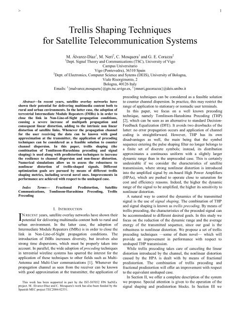
AWGNSamplingTH Decoder2SourcePulseWhitenedbitsQAMTH <strong>Trellis</strong>ComplexDecided bits<strong>Shaping</strong>Predistorter HPA ChannelMatchedSlicerDemapperMapping<strong>Shaping</strong>ModuloFilterFilterFig. 1. Block diagram of the proposed system model, including <strong>Trellis</strong> <strong>Shaping</strong> and Predistortion techniquesdiscuss the different signal shaping alternatives we areconsidering <strong>for</strong> evaluation of the proposed transmissionscheme. In Section IV we present the results offered bysimulations and extract the relevant conclusions. Finally, inSection V we summarize the main outcomes of our research.II. SYSTEM DESCRIPTIONFig. 1 shows the main blocks of the proposed transmissionscheme. The QAM sequence enters the TH Precoder-Shaper,whose output is converted to wave<strong>for</strong>m by the pulse shapingfilter (a square-root raised cosine). Predistortion is applied tothe wave<strong>for</strong>m be<strong>for</strong>e the HPA block, which is the last stage atthe transmitter side. The channel is a tapped delay lineintroducing considerable ISI, according to a typical model ofIMR channel power-delay profile (PDP), and AWG noise. Fig.2 shows the PDP we have used throughout our study. Thereceiver front-end filter is the Whitened-Matched Filter(WMF) [2], which is the optimum receive filter yielding asignal composed of ISI distorted symbols in AWGN. Itsoutput is sampled at symbol rate be<strong>for</strong>e the TH-decodereliminates the remaining ISI and yields the estimated symbolsequence.Signal Power (dBm)-50-55-60-65-70-75-80-85-90-95-100IMR Channel - Power Delay Profile0 20 40 60 80 100 120Delay/T (symbol periods)Fig. 2. Power Delay Profile of the IMR channel used <strong>for</strong> evaluationA. Tomlinson-Harashima Precoding and Signal <strong>Shaping</strong>THP can be seen as a way of per<strong>for</strong>ming pre-equalization atthe transmitter side, with the exception that a (nonlinear)modulo operation is per<strong>for</strong>med on the pre-equalized signal. Bydoing this, the likely increase in power of the pre-equalizedsignal is avoided at the cost of introducing the nonlinearity.Like pre-equalization, THP requires the channel response tobe estimated. The transmitted signal can be recovered atreceiver side by means of the same modulo operation used atthe transmitter. The underlying principle in precodedtransmission is that, thanks to the modulo operation, instead ofusing the original QAM symbol we can use a modulocongruentreplica of it, i.e., a complex symbol which isconverted after the modulo operation into the original one.The set of replicas of the original symbols can be grouped inreplicas of the original constellation whose location follows aregular fashion, presenting the properties of a lattice. For amore detailed description of THP, the reader is referred to [2].Signal shaping [2] is achieved by introducing redundancy inthe transmitted signal. In plain THP, only precoded symbolsare transmitted that belong to the constellation replica withless average energy. Here, only one symbol replica among theset of modulo-congruent symbols causes the precoded symbolto lie within the allowed transmission region. However, insignal shaping, the allowed transmission region is enlarged(usually by a factor of two, as is our case). Now, two symbolreplicas are allowed instead of just one. A wise selection ofthe transmitted replica will allow us to effectively shape thetransmitted signal, i.e., to drive its properties towards a desiredgoal. Usually, the main application of shaping is to reduce theaverage transmitted power. Nevertheless, other aims can beachieved by means of shaping, such as reducing the Peak-to-Average Power Ratio (PAPR) or reducing the dynamics of thetransmitted or received signals.While signal shaping can be relatively easily applied tounprecoded QAM transmission, the combination withprecoding is not straight<strong>for</strong>ward at all. This is due to the factthat the precoding operation itself affects strongly the shape ofthe transmitted signal. As a matter of fact, the TH-precodedsignal under typical conditions is almost uni<strong>for</strong>mly distributedwithin the region defined by the modulo operation. The onlyway to achieve shaping on a precoded signal is to per<strong>for</strong>mboth operations jointly, by means of a technique called trellisprecoding. In particular, we will use a variation of it calledshaping without scrambling [2]. Both techniques use a Viterbidecoder within the precoder, which actually selects (decodes)the sequence to be transmitted as the one offering the lowestaccumulated metric. The metric is chosen according to thedesired goal, and thus, a variety of metrics is availabledepending on the characteristics we demand from the shapedsignal. In Section III we describe the metrics we haveconsidered <strong>for</strong> our study. Fig. 3 illustrates the functioning ofthe trellis shaping block.<strong>Shaping</strong>(Viterbi decoder)ReplicaselectionComplexModuloH(z) - 1Fig. 3. Block diagram of the <strong>Trellis</strong> <strong>Shaping</strong> blockAll the benefits offered by shaping come at some cost. Oneof the drawbacks is that, in general, the PAPR of the shapedsignal is increased with respect to the unshaped precoded case.Another one, as we have already said, is the 1 bit redundancy
3needed <strong>for</strong> shaping, which is accommodated by increasing theconstellation size entering the pulse shaping filter. In otherwords, the shaped signal spans twice the area of the signal inthe unshaped precoding case. Thus, if we want to shape a 16-QAM sequence, we will be using a 32-symbol constellationafter the shaping operation. Though it may initially seem thatone bit redundancy would not be enough to achieve shaping itcan be demonstrated that no practical improvements aregained by adding more redundancy. While the extra bit isunavoidable, the increase in PAPR can be kept lowper<strong>for</strong>ming a wise shaping, as we will see in the next sections.B. Fractional PredistortionAs the precoded and shaped signal is processed through thesatellite channel, its properties are changed by the non lineardistortion that is introduced by the on-board HPA. In order tocounteract these effects, fractional predistortion techniquesare considered in the gateway transmitter [3]. The principle ofpredistortion is to process the signal at some point be<strong>for</strong>eentering the HPA so as to compensate in advance thenonlinear distortion that the HPA will introduce, aiming toobtain an overall linear characteristic between the input of thepredistorter and the output of the HPA. Other methods exist,<strong>for</strong> example nonlinear equalization at the receiver side, butpredistortion has the advantage of reducing adjacent channelinterference, since it is applied at the transmitter side.Fractional predistortion works at wave<strong>for</strong>m level, operatingon the signal samples at the output of the pulse shaping filter,by inverting the amplifier characteristic according to a givenmodel of the HPA. In this study, we considered an on-boardtraveling wave tube (TWT) amplifier whose AM/AM andAM/PM distortion characteristics are shown in Fig. 4.OB O [d B]0.00-2.00-4.00-6.00-8.00-10.00-12.00-14.00-16.00-25.00 -20.00 -15.00 -10.00 -5.00 0.00 5.00 10.00 15.00IBO [dB]Fig. 4. TWTA AM/AM and AM/PM Characteristics50454035302520151050-20,00 -15,00 -10,00 -5,00 0,00 5,00 10,00 15,00IBO [dB]The HPA characteristics are modeled through a rationalpolynomial model envisaging 5 parameters <strong>for</strong> each of the twocharacteristics. The fitted characteristics are then inverted andused to predistort the processed signal. For the implementationof the predistorter we have chosen an approach based on aLook-Up-Table (LUT), which stores the inverted HPA gainvalues that are computed off-line [4]. A block diagram of afractional predistorter is shown in Fig. 5.Phase [deg]b nPulseshapingx mGain based LUT fractionalpredistorterAmplitude Phase|.| 2 LUT(F)g mHPAFig. 5. Block diagram of the gain-based LUT fractional predistorter.This approach allows reducing the computational burden inthe gateway, as only one LUT access plus one multiplicationare needed to process each sample, and does not hinder thepossibility to periodically update the predistortioncharacteristics after a calibration/measurement of the HPAcharacteristics that may have changed due to ageing.III. METRIC SELECTIONThe selection of the metric used in the Viterbi algorithm of theshaper must be driven by the improvement we desire toachieve through shaping. Standard objectives such asminimizing the average transmitted power can be mapped intowell-known metrics, as we will next see. However, some othergroup of objectives do not offer a simple translation into ametric <strong>for</strong>mula, thus requiring research ef<strong>for</strong>ts in order to finda suitable working metric. In this section we describe the setof improvements we have pursued by means of shaping andtheir corresponding metrics.A. Minimization of average energyThis is the most common use of shaping. The goal is toachieve a reduction in the energy of the precoded sequence incomparison to the unshaped signal. The save in energy iscalled shaping gain (G S ). A natural way to build the metric isthus to accumulate the instantaneous energy of each of thesequence samples. The metric <strong>for</strong> each transition k of thetrellis reads( )2λ k = x k , (1)being x k the (candidate to) precoded symbol.B. Joint minimization of average energy and Peak-to-Average Energy RatioThe quadratic order of the metric (1) minimizes the averageenergy of the precoded signal. However, it is possible tosubstitute the power 2 by a generic power s:( )sx kλ k = . (2)If we choose s > 2, the optimal reduction of energy will not befully achieved, but we will be able to reduce the PAR. This isso because the metric penalizes the highest energies in theshaped signal, thus reducing the PAR in comparison to thecase s = 2. A trade-off must be found between theminimization of the average energy (s = 2) and the maximumreduction of the PAR (s → ∞). We have done this empirically.The results are shown in section IV.Metric (2) admits a refinement. By setting a givenamplitude threshold ρ we could differentiate between tworegions: if the amplitude of the precoded symbol is below thethreshold normal energy minimization could be applied (s low =y m
42); instead, when the amplitude is over the threshold we couldapply some other value s high > 2:⎪⎧2xk, if xk≤ ρλ( k ) = ⎨.s(3)high⎪⎩ xk, if xk> ρAgain, the selection of the pair (ρ,s high ) must be doneempirically.C. Minimization of the dispersion of the shaped signal withrespect to a given radius ρConsidering the presence of the HPA, it would be desirableto adapt the characteristics of its input signal to prevent asmuch distortion as possible. One possibility is to try toconcentrate around a circle of fixed radius ρ as much of theshaped signal as possible. In this way we would be (a) makingour shaped signal resemble a PSK signal (circularconstellations are accepted as the most appropriatemodulations <strong>for</strong> satellite transmission) and (b) reducing itsPAR at the same time. The metric we propose <strong>for</strong> doing this isλ( k)x kmsm= − ρ , (4)where s, similarly to metric (2) can be tuned in this case topenalize the dispersion around the circle of radius ρ, and mallows exploration of a wide range of possibilities. Theselection of the best pair (m,s) seems to be bound to anempirical search. In Section IV we present the values we haveobtained.D. Minimizing the perturbation between consecutivesymbolsAnother way to avoid the distortion introduced by the HPAcan be to prevent large transitions between consecutivesymbols of the precoded sequence. If the sequence to betransmitted presents few of such variations, it is likely that theHPA will introduce less distortion. We propose the followingtransition metric:sm mk = x k − xk−1( )λ . (5)As in the previous cases, a theoretical selection of the mostappropriate pair (m,s) seems complicated, and one must revertto empirical search. We show our results in the next section.IV. NUMERICAL RESULTSIn order to search <strong>for</strong> the best set of parameters <strong>for</strong> eachmetric, we have conducted a number of numerical simulations,testing a large variety of parameter combinations.In Table I we show one case of interest <strong>for</strong> each of themetrics presented in Section III. The metrics of Table I haveeither proved to per<strong>for</strong>m well in terms of BER or offer aninteresting trade-off between G S and PAR. As a measure ofPAR we use the peak to average energy ratio of the simulatedsequence considering its peak to be the 99% percentile of theempiric cumulative density function of the sequence. This isrepresented by PAR 99 . For the sake of comparison, we haveincluded the per<strong>for</strong>mance of THP when no shaping is applied.Metric (1) achieves the maximum G S (0.42 dB) as well as ahigh PAR (5 dB). The rest of seleceted metrics are able toreduce the 5 dB PAR while avoiding shaping loss or evenmaintaining part of it.TABLE ICOMPARISON OF THE PROPOSED METRICSMetric Parameters G S (dB) PAR 99 (dB)THP — 0 4.12(1) s = 2 0.42 5.01(2) s = 4 0.34 4.49(3) ρ = 0.6, s high = 4 0.36 4.49(4) m = 1, s = 4, ρ = 0.5 0.25 4.25(5) m = 5, s = 1 0.24 4.22The per<strong>for</strong>mance is compared in terms of G S and PAR 99. Plain THP (noshaping) is included <strong>for</strong> reference.The per<strong>for</strong>mance in terms of BER is shown in Fig. 6 andFig. 7. We include here the per<strong>for</strong>mance of all cases of TableI except metric (5), because this metric does not achieve anacceptable per<strong>for</strong>mance in terms of BER, despite offering agood trade-off between G S and PAR.Fig. 6 contains the per<strong>for</strong>mance of the metrics when nopredistortion is applied. The cases <strong>for</strong> linear HPA, IBO = 10dB and IBO = 2 dB are shown. First of all, the improvement inper<strong>for</strong>mance of shaping is clear, since a visible gap inper<strong>for</strong>mance can be seen between unshaped THP and <strong>for</strong> thelinear case and <strong>for</strong> IBO = 10 dB. In the linear case, the gapamounts close to 1 dB, which is considerable. For IBO = 10dB, a per<strong>for</strong>mance floor is found. This is certainly due to thefact that nonlinear distortion strongly affects the precoded andshaped signals. However, it can be seen that THP is moreseverely affected than trellis shaping. For IBO = 2 dB, theper<strong>for</strong>mance floor is even more severe and no differences arenoticeable between THP and trellis shaping.Fig. 7 shows the per<strong>for</strong>mance when predistortion is used<strong>for</strong> counteracting the effect of the HPA. The cases <strong>for</strong> IBO =10 dB and IBO = 2 dB are shown (the linear case is not shownsince no predistortion is needed in this case). The main resultthat can be extracted from the comparison between Fig. 6 andFig. 7 is that the introduction of predistortion greatlyimproves the per<strong>for</strong>mance of the system. In fact, theper<strong>for</strong>mance floor <strong>for</strong> IBO = 10 dB that is present in Fig. 6 iscompletely removed by predistortion, and the per<strong>for</strong>mancereaches the same level as in the linear case. A greatimprovement is also achieved <strong>for</strong> the IBO = 2 dB case,reducing the BER floor almost one order of magnitude.Another interesting effect can be seen in Fig. 7. While whenno predistortion is applied THP per<strong>for</strong>ms worse than trellisshaping, when predistortion is used it happens the same, butnow the per<strong>for</strong>mance gap is even larger. This is clearly seen<strong>for</strong> the case IBO = 10 dB, where the improvement reachesalmost 2 dB.V. CONCLUSIONSWe have shown that the introduction of signal shaping in the<strong>for</strong>m of trellis precoding improves the per<strong>for</strong>mance of asatellite system using unshaped THP. <strong>Trellis</strong> precoding allowsa reduction in the average energy of the transmitted sequence(shaping gain) in comparison with unshaped THPtransmission. This is certainly of interest considering thepower restrictions that are present in satellite transmission dueto the presence of the HPA. One drawback of signal shaping isthat the PAR of the transmitted signal is increased. However,we have shown that the use of wise trellis precoding schemes
5can keep the PAR at the same level as in unshaped THPtransmission, while still providing some shaping gain.In terms of BER, trellis precoding per<strong>for</strong>ms better thanunshaped THP. If no nonlinearities are present the gap inper<strong>for</strong>mance can be around 1 dB. The introduction ofpredistortion leads to a great improvement in the per<strong>for</strong>manceof the proposed system. In this regard, the trellis-precodedsignal gets more benefit from predistortion than the unshapedsignal: the gap in per<strong>for</strong>mance can reach 2 dB <strong>for</strong> IBO = 10dB.[3] P. Salmi, M. Neri, and G.E. Corazza, “Design and Per<strong>for</strong>mance ofPredistortion <strong>Techniques</strong> in Ka-band <strong>Satellite</strong> Networks”, AIAA,Twenty-second International Communication <strong>Satellite</strong> <strong>Systems</strong>Conference (ICSSC), May 2004, Monterey[4] P. Salmi, M. Neri, and G.E. Corazza, “Fractional Predistortion<strong>Techniques</strong> with Robust Modulation Schemes <strong>for</strong> Fixed and MobileBroadcasting”, IST Mobile Summit 2004, Lion, May 2004[5] M. Álvarez-Díaz, M. Neri, C. Mosquera and G. E. Corazza, “Jointprecoding and predistortion techniques <strong>for</strong> satellite telecommunicationsystems,” presented at IWSSC 2005, Siena, Italy, September 8-9,2005.Per<strong>for</strong>mance without Predistortion10 0 E b/N 0(dB)IBO=2dB10 -1BER10 -210 -310 -4THPFisherClassicPowerThresholdDispersionIBO=10dBLinear0 2 4 6 8 10 12 14 16 18 20Fig. 6. Per<strong>for</strong>mance in terms of BER of the proposed system when nopredistortion is usedPer<strong>for</strong>mance using Predistortion10 0 E b/N 0(dB)IBO=2dB10 -1BER10 -210 -310 -4THPFisherClassicPowerThresholdDispersionIBO=10dB0 2 4 6 8 10 12 14 16 18 20Fig. 7. Per<strong>for</strong>mance in terms of BER of the proposed system whenpredistortion is addedREFERENCES[1] C. Windpassinger, R. F. H. Fischer, T. Vencel, and J. B. Huber,“Precoding in multi-antenna and multi-user communications”, IEEETrans. on Wireless Comm., Vol. 3, No. 4, pp. 1305– 1316, July 2004.[2] R. F. H. Fischer, Precoding and Signal <strong>Shaping</strong> <strong>for</strong> DigitalTransmission, New York, John Wiley & Sons, 2002.