DH100ACDCLP Air Duct Smoke Detector with Extended Air Speed ...
DH100ACDCLP Air Duct Smoke Detector with Extended Air Speed ...
DH100ACDCLP Air Duct Smoke Detector with Extended Air Speed ...
- No tags were found...

Create successful ePaper yourself
Turn your PDF publications into a flip-book with our unique Google optimized e-Paper software.
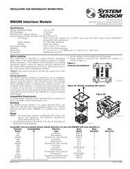
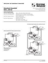
Wiring InstructionsThe <strong>DH100ACDCLP</strong> detectors are designed for easy wiring.The housing provides a terminal strip <strong>with</strong> clamping plates.Wiring connections are made by stripping about 3 /8″ of insulationfrom the end of the wire, sliding the bare end underthe plate, and tightening the clamping plate screw.[5.7] Perform <strong>Detector</strong> Check1. Perform STANDBY AND TROUBLE TEST per Section[6.2.1].2. Perform MAGNET TEST per Section [6.2.2.1]. TheRTS451 test of Section [6.2.2.2] may substitute for thisrequirement.3. Perform AIR FLOW TEST per Section [6.1.1].4. Perform SMOKE RESPONSE TEST per Section [6.1.2].5. Perform SENSITIVITY TEST per Section [6.2.3].[5.8] Install The CoverInstall the cover using the six screws that are captured inthe housing cover. Be certain filters are installed as specifiedin Section [5.5]. Make sure that the cover fits into thebase groove and that all gaskets are in their proper positions.Tighten the six screws.[6] <strong>Duct</strong> <strong>Smoke</strong> <strong>Detector</strong> Maintenance And TestProceduresTest and maintain duct smoke detectors as recommendedin NFPA 72. The tests contained in this manual weredevised to assist maintenance personnel in verification ofproper detector operation.Before conducting these tests, notify the proper authoritiesthat the smoke detection system will be temporarily out ofservice. Disable the zone or system under test to preventunwanted alarms.[6.1] <strong>Smoke</strong> Entry Tests[6.1.1] <strong>Air</strong> FlowThe <strong>DH100ACDCLP</strong> is designed to operate over an extendedair speed range of 100 to 4000 FPM. To verify sufficient samplingof ducted air, turn the air handler on and use amanometer to measure the differential pressure between thetwo sampling tubes. The differential pressure should measureat least 0.0015 inches of water and no more than 1.2inches of water. Because most commercially availablemanometers cannot accurately measure very low pressuredifferentials, applications <strong>with</strong> less than 500 FPM of duct airspeed may require one of the following: 1) the use of a current-sourcingpressure transmitter (Dwyer model numbers607-1 or 607-01) see field bulletin Z75-79-00 or; 2) the useof aerosol smoke per section 6.1.2.[6.1.2] <strong>Air</strong> Flow Test using Aerosol <strong>Smoke</strong>Drill a 1 ⁄4″ hole 3 feet upstream from the duct smoke detector.With the air handler on, measure the air velocity <strong>with</strong>an anemometer. <strong>Air</strong> speed must be at least 100 FPM. If theair speed is greater than 500 FPM, use a conventionalmanometer to measure differential pressure between thesampling tubes. Spray aerosol smoke* into the duct throughthe 1 ⁄4″ hole for five seconds. Wait two minutes for the ductsmoke detector to alarm. If the duct smoke detector alarms,air is flowing through the detector. Remove the duct smokedetector cover and blow out the residual aerosol smoke fromthe chamber and reset the duct smoke detector. Use ducttape to seal the aerosol smoke entry hole.*Aerosol smoke can be purchased from Home Safeguard Industries,Malibu, CA. Phone: 310/457-5813.To determine if smoke is capable of entering the sensingchamber, visually identify any obstructions. Plug theexhaust and inlet tube holes to prevent ducted air from carryingsmoke away from the detector head, then blow smokesuch as cigarette, cotton wick, or punk directly at the headto cause an alarm. REMEMBER TO REMOVE THE PLUGSAFTER THIS TEST, OR THE DETECTOR WILL NOT FUNC-TION PROPERLY.[6.1.3] Filter ReplacementThe filters do not substantially affect smoke performanceeven when up to 90% of the filter is clogged. Quarterlyvisual inspection usually suffices to determine whether thefilters should be replaced because only a high percentage ofcontamination affects performance. If further testing isrequired, compare differential pressure readings <strong>with</strong> and<strong>with</strong>out the filters installed. If the difference exceeds 10%replace the filters. In no case should the pressure differentialfall below 0.0015 inches of water.[6.2] Standby, Alarm and Sensitivity TestsThe cover must be removed to perform these tests. The useof a remote accessory for visible indication of power andalarm is recommended.[6.2.1] Standby And TroubleStandby — Look for the presence of the flashing green LED. TheLED should flash approximately every 10 seconds.Trouble — If the detector LED does not flash, then the detectorlacks power (check wiring, panel, or powersupply), the detector board is missing (replace),the cover has been missing or not secured properlyfor more than 20 minutes (secure cover properly),or the unit is defective (return for repair).Test —The trouble condition can be caused intentionallyto verify correct operation of the system. Removethe detector board to cause a trouble conditionlocally and at the system control panel.D200-14-00 5 I56-0084-00