Dewalt - DW708 - Electric Radial Arm Mitre Saw - GGH Hire
Dewalt - DW708 - Electric Radial Arm Mitre Saw - GGH Hire
Dewalt - DW708 - Electric Radial Arm Mitre Saw - GGH Hire

Create successful ePaper yourself
Turn your PDF publications into a flip-book with our unique Google optimized e-Paper software.
®<strong>DW708</strong>
14 15 161213311A124111095687A118171926202125222324A2
162810BC2729 31 30 23332 337 37 36 38 34 35 5 4D1E266 40 39D2F34
37G4 4241H1361120114443H24512H343A711A114623H4J19K20L1 47
204M1M2523 11 49 3N17M3N2AN3N4
O6P121P222RQ1Q2
ENGLISHSafety instructionsWhen using Power Tools, always observe the safety regulationsapplicable in your country to reduce the risk of fire, electric shockand personal injury. Read the following safety instructions beforeattempting to operate this product.Keep these instructions in a safe place!General1 Keep work area cleanCluttered areas and benches can cause accidents.2 Consider work area environmentDo not expose Power Tools to humidity.Keep work area well lit.Do not use Power Tools in the presence of inflammable liquids or gases.3 Guard against electric shockPrevent body contact with earthed surfaces (e.g. pipes, radiators,cookers and refrigerators).For use under extreme conditions (e.g. high humidity, when metalswarf is being produced, etc.) electric safety can be improved byinserting an isolating transformer or a (FI) earth-leakage circuit-breaker.4 Keep children awayDo not let children come into contact with the tool or extension cord.Supervision is required for those under 16 years of age.5 Extension cords for outdoor useWhen the tool is used outdoors, always use extension cords intendedfor outdoor use and marked accordingly.6 Store idle toolsWhen not in use, Power Tools must be stored in a dry place andlocked up securely, out of reach of children.7 Dress properlyDo not wear loose clothing or jewellery. They can be caught in movingparts. Preferably wear rubber gloves and non-slip footwear when workingoutdoors. Wear protective hair covering to keep long hair out of the way.8 Wear safety gogglesAlso use a face or dust mask in case the operations produce dust orflying particles.9 Beware of maximum sound pressureTake appropriate measures for the protection of hearing if the soundpressure of 85 dB(A) is exceeded.10 Secure workpieceUse clamps or a vice to hold the workpiece. It is safer and it frees bothhands to operate the tool.11 Do not overreachKeep proper footing and balance at all times.12 Avoid unintentional startingDo not carry the plugged-in tool with a finger on the switch.Be sure that the switch is released when plugging in.13 Stay alertWatch what you are doing. Use common sense.Do not operate the tool when you are tired.14 Disconnect toolShut off power and wait for the tool to come to a complete standstillbefore leaving it unattended. Unplug the tool when not in use,before servicing or changing accessories.15 Remove adjusting keys and wrenchesAlways check that adjusting keys and wrenches are removed from thetool before operating the tool.16 Use appropriate toolThe intended use is laid down in this instruction manual. Do not forcesmall tools or attachments to do the job of a heavy-duty tool. The toolwill do the job better and safer at the rate for which it was intended.Warning! The use of any accessory or attachment or performance ofany operation with this tool, other than those recommended in thisinstruction manual may present a risk of personal injury.17 Do not abuse cordNever carry the tool by its cord or pull it to disconnect from the socket.Keep the cord away from heat, oil and sharp edges.18 Maintain tools with careKeep the tools in good condition and clean for better and saferperformance. Follow the instructions for maintenance and changingaccessories. Inspect the tool cords at regular intervals and,if damaged, have them repaired by an authorized DEWALT repairagent. Inspect the extension cords periodically and replace them ifdamaged. Keep all controls dry, clean and free from oil and grease.19 Check for damaged partsBefore using the tool, carefully check it for damage to ensure that it willoperate properly and perform its intended function. Check formisalignment and seizure of moving parts, breakage of parts and anyother conditions that may affect its operation. Have damaged guardsor other defective parts repaired or replaced as instructed. Do not usethe tool if the switch is defective. Have the switch replaced by anauthorized DEWALT repair agent.20 Have your tool repaired by an authorized DEWALT repair agentThis Power Tool is in accordance with the relevant safety regulations.To avoid danger, electric appliances must only be repaired by qualifiedtechnicians.Additional safety rules for mitre saws• Make sure that the blade rotates in the correct direction. Keep theblade sharp. Do not use blades of larger or smaller diameter thanrecommended. For the proper blade rating refer to the technical data.• Make sure all locking knobs and clamp handles are tight before startingany operation.• Check periodically that the motor air slots are clean and free of chips.• Disconnect the machine from the mains before carrying out anymaintenance work or when changing the blade.• Before using any accessory consult the instruction manual.The improper use of an accessory can cause damage.• Allow the motor to reach full speed before cutting.• Raise the blade from the kerf in the workpiece prior to releasing the switch.• Do not wedge anything against the fan to hold the motor shaft.• Never place either hand in the blade area when the saw is connectedto the electrical power source.• Do not attempt to cut excessively small pieces.• Never attempt to stop a machine in motion rapidly by jamming a tool orother means against the blade; serious accidents can be causedunintentionally in this way.• Do not use cracked or damaged saw blades.• Do not use any abrasive discs.• Do not cut ferrous metals, non-ferrous metals or masonry.• Never use your saw without the kerf plate.• The blade guard on your saw will automatically raise when the arm isbrought down; it will lower over the blade when the arm is raised.The guard can be raised by hand when installing or removing sawblades or for inspection of the saw. Never raise the blade guardmanually unless the saw is turned OFF.• The front section of the guard is louvred for visibility while cutting.Although the louvres dramatically reduce flying debris, there areopenings in the guard and safety glasses should be worn at all timeswhen viewing through the louvres.18 en - 2
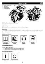
ENGLISHResidual risksThe following risks are inherent to the use of mitre saws:- injuries caused by touching the rotating partsIn spite of the application of the relevant safety regulations and theimplementation of safety devices, certain residual risks cannot be avoided.These are:- Impairment of hearing.- Risk of accidents caused by the uncovered parts of the rotating sawblade.- Risk of injury when changing the blade.- Risk of squeezing fingers when opening the guards.- Health hazards caused by breathing dust developed when sawingwood, especially oak, beech and MDF.<strong>Electric</strong>al safetyThe electric motor has been designed for one voltage only. Always checkthat the power supply corresponds to the voltage on the rating plate.Your DEWALT tool is double insulated in accordance withEN 50144; therefore no earth wire is required.Mains plug replacement (U.K. & Ireland only)• Should your mains plug need replacing and you are competent to dothis, proceed as instructed below. If you are in doubt, contact anauthorized DEWALT repair agent or a qualified electrician.• Disconnect the plug from the supply.• Cut off the plug and dispose of it safely; a plug with bared copperconductors is dangerous if engaged in a live socket outlet.• Only fit 13 Amperes BS1363A approved plugs fitted with the correctlyrated fuse (1).• The cable wire colours, or a letter, will be marked at the connectionpoints of most good quality plugs. Attach the wires to their respectivepoints in the plug (see below). Brown is for Live (L) (2) and Blue is forNeutral (N) (4).• Before replacing the top cover of the mains plug ensure that the cablerestraint (3) is holding the outer sheath of the cable firmly and that thetwo leads are correctly fixed at the terminal screws.Conductor size (mm 2 )Cable rating (Amperes)0.75 61.00 101.50 152.50 204.00 25Cable length (m)7.5 15 25 30 45 60Voltage Amperes Cable rating (Amperes)115 0 - 2.0 6 6 6 6 6 102.1 - 3.4 6 6 6 6 15 153.5 - 5.0 6 6 10 15 20 205.1 - 7.0 10 10 15 20 20 257.1 - 12.0 15 15 20 25 25 -12.1 - 20.0 20 20 25 - - -230 0 - 2.0 6 6 6 6 6 62.1 - 3.4 6 6 6 6 6 63.5 - 5.0 6 6 6 6 10 155.1 - 7.0 10 10 10 10 15 157.1 - 12.0 15 15 15 15 20 2012.1 - 20.0 20 20 20 20 25 -Unpacking (fig. A1, A2 & B)Remove the saw from the packing material carefully using the carryinghandle (9) and the rails (14). The package contains:1 Assembled sliding compound mitre saw1 <strong>Saw</strong> blade wrench1 60 teeth 305 mm TCT saw blade1 Stabilizer1 Instruction manual1 Exploded drawing• Check for damage to the tool, parts or accessories which may haveoccurred during transport.• Take the time to thoroughly read and understand this manual prior tooperation.• Press down the operating handle (17) and pull out the lock down pin (16),as shown in fig. B.• Gently release the downward pressure and allow the arm to rise to itsfull height.Description (fig. A1 & A2)Your <strong>DW708</strong> sliding compound mitre saw has been designed forprofessional cutting of wood, wood products, aluminium and plastics.It will perform the sawing operations of cross-cutting, bevelling and mitringeasily, accurately and safely.Never use a light socket. Never connect the live (L) or neutral(N) wires to the earth pin marked E or .For 115 V units with a power rating exceeding 1500 W, we recommend tofit a plug to BS4343 standard.Using an extension cableIf an extension cable is required, use an approved extension cable suitablefor the power input of this tool (see technical data). The minimumconductor size is 1.5 mm 2 .When using a cable reel, always unwind the cable completely.Also refer to the table below.A11 ON/OFF-switch2 Lower blade guard3 Fence, right-hand side4 <strong>Mitre</strong> lever5 <strong>Mitre</strong> latch6 <strong>Mitre</strong> scale7 Fence, left-hand side8 Bench mounting holes9 Base10 Base stabiliser11 Bevel lever11A Bevel stop override button12 Bevel stop screw13 <strong>Saw</strong> blade wrench14 Rails15 Dust extraction adapter16 Lock down pinen - 3 19
ENGLISHA217 Operating handle18 Carrying handle19 Rail adjustment screws20 Rail lock knob21 Thumbscrew22 Grooving stop23 Fence adjustment knob24 Handhold25 Kerf plate26 Spindle lock buttonAssemblyTo use the spindle lock, press the button as shown and rotatethe spindle by hand until you feel the lock engage. Continue tohold the lock button in to keep the spindle from turning (fig. D2).• Remove the blade screw (31) and the outer flange (32) (fig. D1).• Install the saw blade (33) onto the inner flange making sure that theteeth at the bottom edge of the blade are pointing toward the back ofthe saw (away from the operator).• Replace the outer flange (32).• Tighten the blade locking screw (31) by turning counter-clockwise whileholding the lower guard up and the spindle lock engaged with yourother hand.Prior to assembly always unplug the tool.The motor and guards are already assembled onto the base.Stabilizer (fig. C)Your saw includes one base stabilizer (10).• Insert the stabilizer into the holes (27).• Move the stabilizer in or out until it contacts the work surface.• Tighten the screws (28).AdjustmentNever press the spindle lock while the blade is rotating.Prior to adjustment always unplug the tool.Your mitre saw was accurately adjusted at the factory. If readjustment dueto shipping and handling or any other reason is required, follow the stepsbelow to adjust your saw. Once made, these adjustments should remainaccurate.Never use your saw without the stabilizer.Bench mounting (fig. A2)• Holes (8) are provided in all four feet to facilitate bench mounting.Two different sized holes are provided to accommodate different sizesof bolts. Use either hole; it is not necessary to use both. Always mountyour saw firmly to prevent movement. To enhance the portability,the tool can be mounted to a piece of 12.5 mm or thicker plywoodwhich can then be clamped to your work support or moved to otherjob sites and reclamped.• When mounting your saw to a piece of plywood, make sure that themounting screws do not protrude from the bottom of the wood.The plywood must sit flush on the work support. When clamping thesaw to any work surface, clamp only on the clamping bosses wherethe mounting screw holes are located. Clamping at any other point willinterfere with the proper operation of the saw.• To prevent binding and inaccuracy, be sure the mounting surface is notwarped or otherwise uneven. If the saw rocks on the surface, place athin piece of material under one saw foot until the saw is firm on themounting surface.Mounting the saw blade (fig. A1, A2, D1 & D2)The teeth of a new blade are very sharp and can bedangerous.Lock the mitre lever (4), the rail lock knob (20) and the bevellever (11) (fig. A1 & A2).• Depress the head lock up release lever (50) to release the lower guard(2), then raise the lower guard as far as possible.• Loosen the upper guard cover screw (29) and pivot the upper guard (30) up.Never replace the screw (29) with a different screw!• Hold the guard up, press the spindle lock button (26) (fig. D2) andloosen the blade screw (31) by turning clockwise using the saw bladewrench (fig. D1).Checking and adjusting the blade to the fence (fig. E)• Loosen the mitre lever (4) and squeeze the mitre latch (5) upwards torelease the scale/mitre arm assembly (34).• Swing the mitre arm until the latch locates it at the 0° mitre position.Do not tighten the lever (4).• Pull down the head until the blade just enters the saw kerf (35).• Place a square (36) against the lower part (37) of the fence (7) andblade (33).Do not touch the tips of the blade teeth with the square.If adjustment is required, proceed as follows:• Loosen the four screws (38) and move the scale/mitre arm assembly (34)left or right until the blade is at 90° to the fence as measured withthe square.• Retighten the four screws (38). Pay no attention to the reading of themitre pointer at this point.Adjusting the mitre pointer (fig. F)• Loosen the mitre lever and squeeze the mitre latch to release thescale/mitre arm assembly (34).• Move the saw arm to set the mitre pointer (39) to the zero position.• With the mitre clamp knob loose, allow the mitre latch to snap intoplace as you rotate the mitre arm past zero.• Observe the pointer (39) and mitre scale (6). If the pointer does notindicate exactly zero, loosen the screw (40) and gently move thepointer left or right.• Retighten the screw (40).<strong>Mitre</strong> lock/detent rod adjustment (fig. G)If the base of the saw can be moved while the mitre lever (4) is locked,the mitre lock/detent rod (41) should be adjusted.• Unlock the mitre lever (4).• Fully tighten the mitre lock/detent rod (41) by turning it clockwise usinga screwdriver (42). Turn counterclockwise 1/4 of a turn.• Check that the table will not rotate when the lever (4) is locked at arandom (not preset) angle.20 en - 4
ENGLISHBevel stop adjustment (fig. H1 - H4)Adjusting the bevel stop and pointer to 0° (fig. H1 & H2)• Place the saw in the 0° bevel position (fig. H1).• Push the head fully back and tighten the rail lock knob (20) (fig. H2).• Place a set square (36) on the table and up against the blade (33) (fig. H1).Do not touch the tips of the blade teeth with the square.If adjustment is required, proceed as follows:• Loosen the bevel lever (11) (fig. H2).• Press the mitre arm to the right, against the 0° bevel stop.• Adjust the screw (43) until the blade is perpendicular to the base.• Tighten the lever (11) securely.• Make sure the bevel pointer (44) indicates exactly 0°.• If not, loosen the screw (45), set the pointer to 0° and tighten the screw.• To stop the tool, release the switch.• There is no provision for locking the switch ON, but a hole (47) isprovided for insertion of a padlock to lock the saw OFF.Basic saw cuts (fig. A1, A2, M1 - M3)Vertical straight cross cut (fig. A1 & A2)• Loosen the mitre lever (4) and squeeze the mitre latch (5) upwards.• Engage the mitre latch at the 0° position and tighten the lever (4).• Place the wood to be cut against the fences (3) and (7).• Take hold of the operating handle and depress the head lock uprelease lever (50) to release the head.• With the rail lock knob tightened, switch the saw ON.• Lower the head to allow the blade to cut through the workpiece andenter the kerf plate (25).• After completing the cut, release the switch, let the blade come to a fullstop and return the head to its upper rest position.Adjusting the bevel stop to 45° left or right (fig. H2 - H4)First, adjust the 0° bevel angle.- Left 45° bevel angle• Loosen the bevel lever (11) and tilt the head to the left (fig. H3).• If the pointer (44) does not indicate exactly 45°, turn the screw (12)on the left side until the pointer reads 45° (fig. H2).- Right 45° bevel angle• Depress the bevel stop override button (11A) and tilt the head to theright (fig. H4).• If the pointer does not indicate exactly 45°, turn the screw (43A) onthe lower right side until the pointer reads 45° (fig. H3).Adjusting the fence (fig. A1 & J)The fences (3) and (7) can be adjusted to provide clearance, allowing thesaw to bevel to a full 48°.• Loosen the fence adjustment knob (23) and slide the fence to therequired position (fig. J).• Make a dry run with the saw turned OFF and check for clearance.Adjust the fence to be as close to the blade as practical to providemaximum workpiece support, without interfering with the up and downmovement of the arm.• Firmly tighten the fence adjustment knob (23).• Move the fences back after the cut has been accomplished.When bevelling to the right, it may be necessary to remove theright fence (3) (fig. A1)Rail guide adjustment (fig. K)• Regularly check the rails for clearance.• To reduce clearance, gradually rotate the set screws (19) clockwisewhile sliding the saw head back and forth.Instructions for useAlways observe the safety instructions and applicable regulations.The attention of UK users is drawn to the “woodworkingmachines regulations 1974” and any subsequent amendments.Prior to operation:• Make sure the guards have been mounted correctly. The saw bladeguard must be in closed position.• Make sure the saw blade rotates in the direction of the arrow on the blade.Switching ON and OFF (fig. L)• To run the tool, press the ON/OFF-switch (1).Workpieces larger than 50 x 100 mm (fig. M1)The guide rail allows cutting larger workpieces using an out-down-back motion.• Release the rail lock knob (20).• Pull the saw towards you, lower the saw into the workpiece and push itback to complete the cut.• Proceed as described above.Vertical mitre cross-cut (fig. M2)• Loosen the fence clamping knobs and adjust the fences.• Loosen the mitre lever (4) and squeeze the mitre latch (5) upwards.Move the head left or right to the required angle.• Always ensure that the lever (4) is locked tightly before cutting.• Proceed as for a vertical straight cross-cut.Bevel cuts (fig. M3, H2 & H4)• Loosen the fence clamping knobs (23) and adjust the fences (3) and (7).Loosen the bevel lever (11) and set the required angle.• Tighten the lever (11) firmly.• To bevel to the right, depress the bevel stop override button (11A).Bevelling 48° to the left (fig. H2 & H3)To set a bevel angle greater than 45°, the bevel stop must be adjusted.• Loosen the bevel lever (11) and tilt the head to the left.• Turn the screw (12) until the pointer (44) indicates the desired bevelangle (up to 48°).Bevelling 48° to the right (fig. H2 - H4)To set a bevel angle greater than 45°, the bevel stop must be adjusted.• Depress the bevel stop override button (11A) and tilt the head to theright.• Turn the screw (43A) until the pointer (44) indicates the desired bevelangle (up to 48°).Quality of cutThe smoothness of any cut depends on a number of variables, e.g. thematerial being cut. When smoothest cuts are desired for moulding andother precision work, a sharp (60 tooth carbide) blade and a slower,even cutting rate will produce the desired results.Ensure that the material does not creep while cutting; clamp itsecurely in place. Always let the blade come to a full stopbefore raising the arm. If small fibres of wood still split out atthe rear of the workpiece, stick a piece of masking tape on thewood where the cut will be made. <strong>Saw</strong> through the tape andcarefully remove tape when finished.en - 5 21
ANGLE OF SIDE OF BOX (ANGLE"A")ENGLISHBody and hand positionProper positioning of your body and hands when operating the mitre sawwill make cutting easier, more accurate and safer.• Never place your hands near the cutting area.• Place your hands no closer than 150 mm from the blade.• Hold the workpiece tightly to the table and the fence when cutting.Keep your hands in position until the switch has been released and theblade has completely stopped.• Always make dry runs (without power) before finish cuts so that youcan check the path of the blade.• Do not cross your hands.• Keep both feet firmly on the floor and maintain proper balance.• As you move the saw arm left and right, follow it and stand slightly tothe side of the saw blade.• Sight through the guard louvres when following a pencil line.Clamping the workpiece (fig. M3)Always use a material clamp when cutting non-ferrous metals.• Whenever possible, clamp the workpiece to the saw.• For best results use the clamp (49) (DE7082) made for use with yoursaw (available from your dealer as an option). Clamp the workpiece tothe fence. You can clamp to either side of the saw blade; remember toposition your clamp against a solid, flat surface of the fence.Compound mitre (fig. N3 & N4)A compound mitre is a cut made using a mitre angle and a bevel angle atthe same time. This is the type of cut used to make frames or boxes withslanting sides like the one shown in fig. N3.If the cutting angle varies from cut to cut, check that the beveland mitre levers are securely tightened.• The chart shown below will assist you in selecting the proper bevel andmitre settings for common compound mitre cuts. To use the chart,select the desired angle “A” (fig. N4) of your project and locate thatangle on the appropriate arc in the chart. From that point follow thechart straight down to find the correct bevel angle and straight acrossto find the correct mitre angle.• Set your saw to the prescribed angles and make a few trial cuts.• Practice fitting the cut pieces together.• Example: To make a 4 sided box with 25° exterior angles (angle “A”)(fig. N4), use the upper right arc. Find 25° on the arc scale. Follow thehorizontal intersecting line to either side to get the mitre angle settingon the saw (23°). Likewise follow the vertical intersecting line to the topor bottom to get the bevel angle setting on the saw (40°). Always trycuts on a few scrap pieces of wood to verify the settings on the saw.450 5 10 15 20 25 30 35 40 45Always use a clamp when cutting small workpieces.4085807570656055SQUARE BOX40Support for long workpieces• Always support long workpieces.• For best results, use the extension work support (DE7080) to extendthe table width of your saw (available from your dealer as an option).Support long workpieces using any convenient means such as sawhorsesor similar devices to keep the ends from dropping.Cutting picture frames, shadow boxes & other four sided projects(fig. N1 - N4)Trim moulding and other framesTry a few simple projects using scrap wood until you develop a “feel” foryour saw. Your saw is the perfect tool for mitring corners like the one shownin fig. N1. The joint shown has been made using either bevel adjustment.SET THIS MITER ANGLE ON SAW3530252015105858580807575707065658 SIDED BOX60605555504545405035353025252020154030506 SIDED BOX15101055454035302520151053530252015105Using bevel adjustmentThe bevel for the two boards is adjusted to 45° each, producing a 90°corner. The mitre arm is locked in the zero position. The wood ispositioned with the broad flat side against the table and the narrow edgeagainst the fence.Using mitre adjustmentThe same cut can be made by mitring right and left with the broad surfaceagainst the fence.The two sketches (fig. N1 & N2) are for four side objects only. As thenumber of sides changes, so do the mitre and bevel angles. The chartbelow gives the proper angles for a variety of shapes, assuming that allsides are of equal length. For a shape that is not shown in the chart, divide180° by the number of sides to determine the mitre or bevel angle.No. of sidesAngle mitre or bevel4 45°5 36°6 30°7 25.7°8 22.5°9 20°10 18°0 5 10 15 20 25 30 35 40 45SET THIS BEVEL ANGLE ON SAWDual range mitre scale (fig. O)The mitre scale has two ranges of numbers for convenience, as shown infig. O. One scale indicates 0° when the blade is square to the fence.At this position the other scale reads 90°. The 0° scale (larger numberscloser to the front edge) is used when calculating angles. To calculate theproper mitre angle, divide 180° by the number of sides of the box orframe. Refer to the previous chart for some examples. The 90° scale(smaller numbers behind the 0° scale) is used when a corner of your boxor frame is measured with a protractor. For example, if you measure thecorner of an 8 sided box, the protractor will read 135°. To determine theproper mitre setting, divide the measured angle by two. The proper mitresetting in this example is 67 1 /2. Set this angle on the 90° scale.Vernier scale (fig. P1 - P3)Your saw is equipped with a vernier scale for added precision. For settingsthat require partial degrees ( 1 /4°, 1 /2°, 3 /4°), the vernier scale allows you toaccurately set mitre angles to the nearest 1 /2° (15 minutes). To use thevernier scale follow the steps listed below.As an example, assume that the angle you want to mitre is 24 1 /2° right.• Turn OFF the mitre saw.22 en - 6
ENGLISH• Set the mitre angle to the nearest whole degree desired by aligning thecentre mark in the vernier scale, shown in (fig. P1), with the wholedegree number etched in the mitre scale. Examine (fig. P1) closely;the setting shown is 24° right mitre.• To set the additional 1 /2°, squeeze the mitre arm lock and carefullymove the arm to the right until the 1 /2° vernier mark aligns with theclosest degree mark on the mitre scale. In this example, the closestdegree mark on the mitre scale happens to be 25°. Fig. P2 shows asetting of 24 1 /2° right mitre.When mitring to the right:- increase the mitre angle by moving the arm to align the appropriatevernier mark with the closest mark on the mitre scale to the right.- decrease the mitre angle by moving the arm to align the appropriatevernier mark with the closest mark on the mitre scale to the left.When mitring to the left:- increase the mitre angle by moving the arm to align the appropriatevernier mark with the closest mark on the mitre scale to the left.- decrease the mitre angle by moving the arm to align the appropriatevernier mark with the closest mark on the mitre scale to the right.Cutting base mouldings (fig. Q1 - Q4)Vertical position• Always make a dry run without power before making any cuts.Straight 90° cuts (fig. Q1)• Position the wood against the fence as shown in fig. Q1.• Turn the saw ON, allow the blade to reach full speed and lower the armsmoothly through the cut.Outside corner- Left side• Position the moulding with the bottom of the moulding againstthe fence.• Save the right side of the cut.- Right side• Position the moulding with top of the moulding against the fence.• Save the right side of the cut.Grooving (fig. R)Your saw is equipped with a grooving stop (22) and thumbscrew (21) toallow for groove cutting.• Flip the grooving stop (22) towards the front of the saw.• Adjust the thumbscrew (21) to set the depth of the groove cut.Cutting non-ferrous metalsWhen cutting non-ferrous metals, the machine is only to be used toperform vertical straight and mitre cross-cuts in the mitre saw mode.We recommend that bevel and compound mitre cuts should not beperformed in non-ferrous metals. The machine is not to be used for cuttingferrous metals.• Always use a material clamp when cutting non-ferrous metals.Make sure that the workpiece is clamped securely.• Only apply saw blades that are qualified for cutting non-ferrous metals.• When using lubricants, only apply wax or separation spray. Do not useemulsions or similar fluids.• Connect an FI or DI switch between machine and mains to avoidresidual risks caused by metal swarf.The FI switch should comply with the following specifications:45° mitre cuts (fig. Q2)• Position the moulding as shown in fig. Q2.• All cuts are made with the back of the moulding against the fence andthe bottom of the moulding against the base.rated voltagerated currentreaction timefusing current230 V16 A< 15 ms30 mAInside corner- Left side• <strong>Mitre</strong> left 45°.• Save the left side of the cut.- Right side• <strong>Mitre</strong> right 45°.• Save the right side of the cut.Outside corner- Left side• <strong>Mitre</strong> right 45°.• Save the left side of the cut.- Right side• <strong>Mitre</strong> left 45°.• Save the right side of the cut.Horizontal position using bevel (fig. M3)Another method of making the cut is to make a 0° mitre, 45° bevel cut.All cuts are made with the back of the moulding laying flat on the saw asshown in fig. M3.Inside corner- Left side• Position the moulding with top of the moulding against the fence.• Save the left side of the cut.- Right side• Position the moulding with the bottom of the moulding against the fence.• Save the left side of the cut.The DI switch should comply with the following specifications:DIN VDE 0661rated voltagerated currentfusing currentall-pole cutoffPE monitoringlow-voltage release230 V16 A30 mAL+N+PEConsult your dealer for further information on the appropriate accessories.These include various saw blades, extension kits (DE7080), adjustablelength stops (DE7051), vertical clamps (DE7082), crown stops (DE7084)and dustbags (DE7053).Transport (fig. A1, A2 & B)In order to conveniently carry your saw, a carrying handle (9) has beenincluded on the top of the saw arm (fig. B).• To transport the saw (fig. B), lower the arm and depress the lock downpin (16) (fig. A1).• <strong>Mitre</strong> the saw 60° to the right, lock the mitre lever (4), lock the rail lockknob (20) with the head fully forward, slide the fences (7) completelyinward and lock the bevel lever (11) with the saw at 0° bevel.• Always use the carrying handle (18) and/or the handholds (24) (fig. A2)to transport the saw.en - 7 23
ENGLISHMaintenanceYour DEWALT Power Tool has been designed to operate over a longperiod of time with a minimum of maintenance. Continuous satisfactoryoperation depends upon proper tool care and regular cleaning.LubricationYour Power Tool requires no additional lubrication.CleaningKeep the ventilation slots clear and regularly clean the housing witha soft cloth.Unwanted tools and the environmentTake your tool to an authorized DEWALT repair agent where it will bedisposed of in an environmentally safe way.GUARANTEE• 30 DAY NO RISK SATISFACTION GUARANTEE •If you are not completely satisfied with the performance of yourDEWALT tool, simply return it within 30 days, complete as purchased,to a participating Dealer, or an authorized DEWALT repair agent,for a full refund or exchange. Proof of purchase must be produced.• ONE YEAR FREE SERVICE CONTRACT •If you need maintenance or service for your DEWALT tool, in the12 months following purchase, it will be undertaken free of charge atan authorized DEWALT repair agent. Proof of purchase must beproduced. Includes labour and spare parts for Power Tools.Excludes accessories.• ONE YEAR FULL WARRANTY •If your DEWALT product becomes defective due to faulty materials orworkmanship within 12 months from the date of purchase,we guarantee to replace all defective parts free of charge or,at our discretion, replace the unit free of charge provided that:• The product has not been misused.• Repairs have not been attempted by unauthorized persons.• Proof of purchase date is produced.This guarantee is offered as an extra benefit and is additional toconsumers statutory rights.For the location of your nearest authorized DEWALT repair agent,please use the appropriate telephone number on the back of thismanual.24 en - 8