Elu - TGS173A2 - Electric Flipover Saw - Carey Tool
Elu - TGS173A2 - Electric Flipover Saw - Carey Tool
Elu - TGS173A2 - Electric Flipover Saw - Carey Tool
- No tags were found...

You also want an ePaper? Increase the reach of your titles
YUMPU automatically turns print PDFs into web optimized ePapers that Google loves.
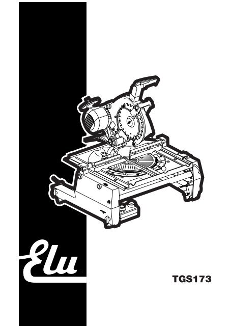
TGS173
11 101A12131415986716175418 19A112320272826212224A22523
434435A6A7B45HB1BHA8B2
345248495051CD5654532256E12619E213 14 5927616030 57F157 62F2
21 6150 1666F363 9 65GH76 75 68 6767 68 75 762480°72J69 70 71 24K173K2737472L17745°L271M1
72779M2 N1 N219 26593030 82 80 81 292 mm3-8 mmOP88 873384Q858683RST
24UVWX194 9491 9093 92X2 X3 Y
FLIP-OVER SAW TGS173ENGLISHCongratulations!You have chosen an <strong>Elu</strong> Power <strong>Tool</strong>. Years of experience, thoroughproduct development and innovation make <strong>Elu</strong> one of the most reliablepartners for professional Power <strong>Tool</strong> users.Table of contentsTechnical data en - 1EC-Declaration of conformity en - 1Safety instructions en - 2Package contents en - 3Description en - 3<strong>Electric</strong>al safety en - 4Mains plug replacement (U.K. & Ireland only) en - 4Using an extension cable en - 4Assembly and adjustment en - 4Instructions for use en - 6Maintenance en - 8Guarantee en - 8Technical dataTGS173Voltage V 230(U.K. & Ireland only) V 230/115(Latin America only) V 120Motor power (input) W 1,650Motor power (output) W 1,100Blade diameter mm 250Blade bore mm 30Max cycle of use load/no load min 1/3No-load speed (50/60 Hz) min -1 3,000/3,600<strong>Saw</strong> head pre-set locations left/right ° 0-45Bevel adjustment ° 0-45Cutting capacitiessee under “Description”Weight kg 38Fuses:Europe 230 V tools 10 Amperes, mainsU.K. & Ireland 230 V tools 13 Amperes, in plugsEC-Declaration of conformityTGS173<strong>Elu</strong> declares that these Power <strong>Tool</strong>s have been designed in compliancewith: 98/37/EEC, 89/336/EEC, 73/23/EEC, EN 61029, EN 55014-2,EN 55014, EN 61000-3-2 & EN 61000-3-3.For more information, please contact <strong>Elu</strong> at the address below or refer tothe back of the manual.Level of sound pressure according to 86/188/EEC & 98/37/EEC,measured according to DIN 45635:TGS173L pA(sound pressure) dB(A)* 83L WA(acoustic power) dB(A) 96* at the operator’s earTake appropriate measures for the protection of hearing if thesound pressure of 85 dB(A) is exceeded.Weighted root mean square acceleration value according to DIN 45675:TÜV RheinlandProduct and Safety GmbH (TRPS)Am Grauen Stein 1D-51105 KölnGermanyDirector Engineering and Product DevelopmentHorst GroßmannTGS173< 2.5 m/s 2Cert. No.BM 9910081 01The following symbols are used throughout this manual:Denotes risk of personal injury, loss of life or damage to thetool in case of non-observance of the instructions in thismanual.Denotes risk of electric shock.Sharp edges.<strong>Elu</strong> International, Richard-Klinger-Straße 40,D-65510, Idstein, Germany18 en - 1
ENGLISHSafety instructionsWhen using Power <strong>Tool</strong>s, always observe the safety regulationsapplicable in your country to reduce the risk of fire, electric shock andpersonal injury. Read the following safety instructions before attemptingto operate this product. Keep these instructions in a safe place!General1 Keep work area cleanCluttered areas and benches can cause accidents.2 Consider work area environmentDo not expose Power <strong>Tool</strong>s to humidity. Keep work area well lit.Do not use Power <strong>Tool</strong>s in the presence of flammable liquids or gases.3 Guard against electric shockPrevent body contact with earthed surfaces (e.g. pipes, radiators,cookers and refrigerators).For use under extreme conditions (e.g. high humidity, when metalswarf is being produced, etc.) electric safety can be improved byinserting an isolating transformer or a (FI) earth-leakage circuit-breaker.4 Keep children awayDo not let children come into contact with the tool or extension cord.Supervision is required for those under 16 years of age.5 Extension cords for outdoor useWhen the tool is used outdoors, always use extension cords intendedfor outdoor use and marked accordingly.6 Store idle toolsWhen not in use, Power <strong>Tool</strong>s must be stored in a dry place andlocked up securely, out of reach of children.7 Dress properlyDo not wear loose clothing or jewellery. They can be caught in movingparts. Preferably wear rubber gloves and non-slip footwear whenworking outdoors. Wear protective hair covering to keep long hair outof the way.8 Wear safety gogglesAlso use a face or dust mask in case the operations produce dust orflying particles.9 Beware of maximum sound pressureTake appropriate measures for the protection of hearing if the soundpressure of 85 dB(A) is exceeded.10 Secure workpieceUse clamps or a vice to hold the workpiece. It is safer and it frees bothhands to operate the tool.11 Do not overreachKeep proper footing and balance at all times.12 Avoid unintentional startingDo not carry the plugged-in tool with a finger on the switch.Be sure that the switch is released when plugging in.13 Stay alertWatch what you are doing. Use common sense.Do not operate the tool when you are tired.14 Disconnect toolShut off power and wait for the tool to come to a complete standstillbefore leaving it unattended. Unplug the tool when not in use, beforeservicing or changing accessories.15 Remove adjusting keys and wrenchesAlways check that adjusting keys and wrenches are removed from thetool before operating the tool.16 Use appropriate toolThe intended use is described in this instruction manual.Do not force small tools or attachments to do the job of a heavy-dutytool. The tool will do the job better and safer at the rate for which it wasintended.Warning! The use of any accessory or attachment and performance ofany operation with this tool, other than those recommended in thisinstruction manual may present a risk of personal injury.17 Do not abuse cordNever carry the tool by its cord or pull it to disconnect from the socket.Keep the cord away from heat, oil and sharp edges.18 Maintain tools with careKeep the tools in good condition and clean for better and saferperformance. Follow the instructions for maintenance and changingaccessories. Inspect the tool cords at regular intervals and,if damaged, have them repaired by an <strong>Elu</strong> authorized repair agent.Inspect the extension cords periodically and replace them if damaged.Keep all controls dry, clean and free from oil and grease.19 Check for damaged partsBefore using the tool, carefully check it for damage to ensure that it willoperate properly and perform its intended function. Check formisalignment and seizure of moving parts, breakage of parts and anyother conditions that may affect its operation. Have damaged guardsor other defective parts repaired or replaced as instructed.Do not use the tool if the switch is defective. Have the switch replacedby an <strong>Elu</strong> authorized repair agent.20 Have your tool repaired by an <strong>Elu</strong> authorized repair agentThis Power <strong>Tool</strong> is in accordance with the relevant safety regulations.To avoid danger, electric appliances must only be repaired by qualifiedtechnicians.Additional safety rules for flip-over saws• Do not use the saw to cut other than aluminium, wood or similar materials.• Connect the machine to a dust collection device when sawing wood.• Select the correct saw blade for the material to be cut.• Use correctly sharpened blades. Observe the maximum speed markedon the sawblade.• Use only saw blades recommended by the manufacturer and whichconform to EN847-1.• Make sure the floor area around the machine is level, well maintainedand free of loose materials e.g. chips and off-cuts.• Make sure adequate general or localized lighting is provided.• Wear suitable personal protective equipment when necessary, including:- hearing protection to reduce the risk of induced hearing loss;- respiratory protection to reduce the risk of inhalation of harmful dust;- gloves for handling saw blades and rough material. <strong>Saw</strong> bladesshould be carried in a holder wherever practicable.• Refrain from removing any cut-offs or other parts of the workpiece fromthe cutting area whilst the saw is running and the saw head is not inthe rest position.• Replace the table insert when worn.• Report faults in the machine, including guards or sawblades,to your dealer as soon as they are discovered.• Ensure that the upper portion of the saw blade is completely enclosedin the mitre sawing mode. Do not use the saw without the guards inposition, in good working order and properly maintained.• Ensure that the arm is securely fixed in the working position in thebench sawing mode.• Ensure that the arm is securely fixed when bevelling in the bench sawmode.• Take care when grooving during the bench saw operation by usingappropriate guarding system. Slotting is not allowed.Additional safety rules for mitre saws• Make sure that the blade rotates in the correct direction. Keep theblade sharp. Do not use blades of larger or smaller diameter thanrecommended. For the proper blade rating refer to the technical data.• Make sure all locking knobs and clamp handles are tight before startingany operation.• Check periodically that the motor air slots are clean and free of chips.• Disconnect the machine from the mains before carrying out anymaintenance work or when changing the blade.en - 2 19
ENGLISH• Before using any accessory consult the instruction manual.The improper use of an accessory can cause damage.• Allow the motor to reach full speed before cutting.• Raise the blade from the kerf in the workpiece prior to releasing theswitch.• Do not wedge anything against the fan to hold the motor shaft.• Never place either hand in the blade area when the saw is connectedto the electrical power source.• Do not attempt to cut excessively small pieces.• Never attempt to stop a machine in motion rapidly by jamming a tool orother means against the blade; serious accidents can be causedunintentionally in this way.• Do not use cracked or damaged saw blades.• Do not use any abrasive discs.Additional safety rules for saw benches• Make sure that the blade rotates in the correct direction and that theteeth are pointing to the front of the saw bench.• Be sure all clamp handles are tight before starting any operation.• Be sure all blade and flanges are clean and the recessed sides of thecollar are against the blade. Tighten the arbor nut securely.• Keep the saw blade sharp and properly set.• Make sure that the riving knife is adjusted to the correct distance formthe blade - 3-8 mm.• Never operate the saw without the upper and lower guards in place.• Keep your hands out of the path of the saw blade.• Disconnect the saw from the mains supply before changing blades orcarrying out maintenance.• Use a push stick at all times, and ensure that you do not place handscloser than 150 mm from the saw blade while cutting.• Do not attempt to operate on anything but the designated voltage.• Do not apply lubricants to the blade when it is running.• Do not reach around behind the saw blade.Residual risksThe following risks are inherent to the use of this saw:- Injuries caused by touching the rotating partsIn spite of the application of the relevant safety regulations and theimplementation of safety devices, certain residual risks cannot beavoided. These are:- Impairment of hearing.- Risk of accidents caused by the uncovered parts of the rotating sawblade.- Risk of injury when changing the blade.- Risk of squeezing fingers when opening the guards.- Health hazards caused by breathing dust developed when sawingwood, especially oak, beech and MDF.Package contentsThe package contains:1 Partly assembled machine4 Legs1 Top guard for bench saw position1 Under-table guard for mitre saw position1 Plastic bag containing:1 pin spanner1 Allen key 6 mm1 Skinpack containing:1 dual height rip fence (E34969)1 push stick1 30 teeth TCT saw blade1 Instruction manual1 Exploded drawing• Check for damage to the tool, parts or accessories which may haveoccurred during transport.• Take the time to thoroughly read and understand this manual prior tooperation.• Remove the saw from the packaging material carefully.Description (fig. A1 - A4)Your <strong>Elu</strong> flip-over sawing machine has been designed to operate as a mitresaw or as a saw bench to perform the four main sawing operations ofripping, cross-cutting, bevelling and mitring easily, accurately and safely,using the following materials: wood, wood products, aluminium and plastic.Mitre saw modeIn mitre saw mode, the sawing machine is used in vertical, mitre or bevelposition.<strong>Saw</strong> bench modeTurned over on its central axis, the sawing machine is used to perform thestandard ripping operation and for sawing wide pieces by manuallyfeeding the workpiece into the blade.A11 On/off-switch1A Trigger switch2 Side panel3 Leg clamping wingnut4 Leg5 Foot6 Mitre saw table7 Fence8 Rotating table location plunger9 Fixed lower rear guard10 Fixed upper blade guard11 Dust extraction adapter12 Head lock release lever13 Blade bolt14 Outer flange15 Moving lower guard16 Rotating table17 Rotating table clamp18 Mitre scales19 Table release leverA220 Control handle21 Depth stop rod22 Height adjuster23 Dust extraction adapter24 Bevel clamp handle25 <strong>Saw</strong> table retention bracket26 Table locking device27 Riving knife clamp knob28 Motor housing<strong>Saw</strong> bench modeA329 Upper blade guard30 Riving knife31 <strong>Saw</strong> bench table32 Mitre fence (optional)33 Dual height parallel fence20 en - 3
ENGLISHOptional accessoriesFor use in mitre saw mode:A332 Mitre fence (E34967)A434 Adjustable stand 760 mm (max. height) (E34901)35 Support guide rails 1,000 mm (E34903)35 Support guide rails 500 mm (E34902)36 Inclinable support (E34922)37 Swivelling stop (E34904)38 Length stop for short workpieces (to be used with guide rails [35])(E34905)39 Support with removable stop (E34908)40 Support with stop removed (E34907)41 Material clamp (E34906)Mains plug replacement (U.K. & Ireland only)• Should your mains plug need replacing and you are competent to dothis, proceed as instructed below. If you are in doubt, contact an <strong>Elu</strong>authorized repair agent or a qualified electrician.• Disconnect the plug from the supply.• Cut off the plug and dispose of it safely; a plug with bared copperconductors is dangerous if engaged in a live socket outlet.• Only fit 13 Amperes BS1363A approved plugs fitted with the correctlyrated fuse (1).• The cable wire colours, or a letter, will be marked at the connectionpoints of most good quality plugs. Attach the wires to their respectivepoints in the plug (see below). Brown is for Live (L) (2), blue is forNeutral (N) (4) and green/yellow is for Earth (E).• Before replacing the top cover of the mains plug ensure that the cablerestraint (3) is holding the outer sheath of the cable firmly and that theleads are correctly fixed at the terminal screws.A542 Roller support table (E34977)For use in saw bench mode:A643 Extension table (EZ31810)A744 Single sliding table (E34970)Push sticks (E38762) (not shown)For use in all modes:A845 Three way dust extraction kit (E34995)Cutting capacitiesCutting capacity in mitre saw modeCutting angle Size of material NotesH mm B mmStraight cross-cut 20 180 No packaging piece required30 17640 17068 14085 68 With 25 mm packaging piece (fig. B1)88 22 With 50 mm packaging piece (fig. B1)15 210 Thin boards only (fig. B2)Table turned 45° toright for mitre cuts 70 95 Cross-cut at max. heightTable turned 45° toleft for mitre cuts 68 93 Cross-cut at max. height<strong>Saw</strong>head tilted 45°for bevel cuts 50 140Cutting capacity in saw bench modeCutting depth adjustment90° vertical cut 0 - 70 mm45° bevel cut 0 - 32 mm<strong>Electric</strong>al safetyThe electric motor has been designed for one voltage only. Always checkthat the power supply corresponds to the voltage on the rating plate.Never use a light socket. Never connect the live (L) or neutral (N)wires to the earth pin marked E or .Using an extension cableIf an extension cable is required, use an approved extension cable suitablefor the power input of this machine (see technical data). The minimumconductor size is 1.5 mm 2 . When using a cable reel, always unwind thecable completely. Also refer to the table below.Conductor size (mm 2 ) Cable rating (Amperes)0.75 61.00 101.50 152.50 204.00 25Cable length (m)7.515 25 30 45 60Voltage Amperes Cable rating (Amperes)230 0 - 2.0 6 6 6 6 6 62.1 - 3.4 6 6 6 6 6 63.5 - 5.0 6 6 6 6 10 155.1 - 7.0 10 10 10 10 15 157.1 - 12.0 15 15 15 15 20 20115-120 12.1 - 20.0 20 20 20 20 25 -Assembly and adjustmentPrior to assembly and adjustment always unplug the tool.The machine is packed in the saw bench mode for compactness and isfully assembled for mitre saw operation except for the legs, under-tableplastic guard and blade.Fitting the legs (fig. C)• Place the machine upside down on the floor.• Loosen the four wingnuts (3) and insert a leg (4) into each of the clamps.• Tighten the wingnuts (3) and turn the table over. Make sure it is level;adjust the leg clamping height if required.en - 4 21
ENGLISHAssembly for mitre saw modeMounting the under-table guard (fig. D)The under-table guard (48) is fitted to the top of the saw bench table.• Place the two hooks on the left of the guard into the oblong slots (49)on the left of the blade slot (50).• Place the guard flat on the table and press it in the locking grommet (51).• To remove, loosen the grommet with a screwdriver (52) and proceed inreverse order.Turning the sawhead and table over (fig. A2, E1 & E2)• Withhold the saw table with one hand and push the table release lever (19)to the left (fig. E1).• Push the table downwards at the front and swing it over completelyuntil the motor assembly is uppermost and the indentation engages inthe retaining teeth of the table locking device (26).• The head assembly is held down by a clamp strap at the front and aheight adjuster (22) at the rear (fig. A2).• Remove the strap.• Rotate the circular wheel (53) counterclockwise whilst holding downthe head until the “U”-shaped bracket (54) can be disengaged from itsseating (fig. E2).• Swing the height adjuster up and push the rod (55) into the clip (56).• Holding the head firmly, allow the spring pressure to take the headupwards into its rest position.Mounting the saw blade (fig. A1, F1 - F3)• The teeth of a new blade are very sharp and can be dangerous.• Always change blades with the machine in mitre saw mode.• The maximum diameter blade that can be fitted is 250 mm.The minimum diameter is 244 mm.• Loosen the riving knife clamping knob (27) and allow the riving knife (30)to swing downwards (fig. F1).• Place the 6 mm Allen key into the end of the blade bolt (13) and thetwo pins of the pin spanner (57) into the holes on the outer flange (14).• The blade bolt has a left-handed thread, therefore holding the spannerfirmly, turn the Allen key clockwise to loosen.• Remove the blade bolt (13) and remove the outer flange (14).• If the blade bolt is too tight, turn the handle of the pin spanner (57) intothe guard and lock it there using a screwdriver (58) (fig. F2). This allowsto exert extra pressure on the Allen key.• The blade (59) has a 30 mm bore, and is located on a step flange (60)on the inner flange (61) (fig. F1).• Press the guard retraction lever (12) and move the head down slightlyto release the lower guard (15) (fig. A1).• Rotate the lower blade guard all the way up and hold it there.• Make sure the inner flange and both faces of the blade are clean andfree of dust.• Place the blade onto the step flange (60) on the inner flange (61),ensuring that the teeth are pointing downwards (fig. F1).• Carefully ease the blade into position and release the lower blade guard.• Also ensure that the two projections (62) on the outer collar are seatedproperly through the inner collar and onto the flats on the spindle.• Tighten the blade bolt securely.• Rotate the blade by hand to check that it rotates freely. If it fouls thelower rear blade guard (9), retighten the crosshead screws (63) (fig. F3).• Reposition the riving knife (30) in the upper rest position and tighten theclamping knob (27) (fig. F1).Adjusting the mitre saw mode depth limiter (fig. G)The handle (64) is connected to a depth stop rod (21) which has aneccentrically positioned adjustable bolt (65) with locknut (66). When the depthlimiter is engaged, the saw head cannot be pulled down completely (fig. G).- Handle to the left = engaged, for use in mitre saw mode(all angles except 0-45° mitre cross cut)- Handle to the right = disengaged, for use in saw bench mode• If the depth limiter needs adjustment, loosen the locknut (66)and screw the bolt (65) in or out as required.Incorrect use of the depth limiter may cause damage to themachine.Adjusting the mitre angle in mitre saw mode (fig. A1, A2 & H)The straight cross-cut and 45° mitre positions are pre-set.• Lift the rotating table clamp (17), pull up the rotating table locationplunger (8) and rotate it counterclockwise a quarter of a turn (fig. A1).• Grip the control handle (20) (fig. A1), compress the guard retractionlever (12) and lower the saw about halfway (fig. A2).• Turn the sawhead with its rotating table to the required position.• Push down the rotating table clamp (17). The rotating table locationplunger (8) will engage automatically (fig. A1).Using the red marks (67), the rotating table (16) can be set to any mitreangle left or right between 0° and 45° (fig. H):- angles between 0° and 30°: use the red marks nearest to the slot- angles between 30° and 45°: use the outer red mark (68)• Proceed as for pre-set positions. The rotating table location plungercannot be used for intermediate angles.Always make a trial cut in a piece of waste wood, to check foraccuracy.Adjusting the bevel position (fig. J)The sawhead can be tilted from the vertical position to 45° left to enablebevel cuts to be made at any angle between these two limits.• Standing behind the machine, release the bevel clamp handle (24)(it allows a ratchet-type action when full rotation of the handle is notpossible).• Tilt the sawhead to the required angle on the bevel scale (69).The pointer (70) is on the fixed cast part of the bevel bracket (71).• Tighten the bevel clamp handle (24) and leave it in horizontal position.Checking and adjusting the blade to the fence (fig. H2, K1 & K2)• With the head in the vertical position and the bevel clamp handle (24)released and raised, slacken the locking screw (72) in the rear of therotating table location plunger (8) (fig. K1).• Place a set square (73) against the fence and along the blade asshown in figure K2. The angle should be 90°.• If adjustment is required, rotate the eccentric adjustment bush (74) untilthe face of the saw blade is flat against the square (fig. K2).• Tighten the locking screw (72).• Check that the red marks (67) nearest the blade slot (50) are in line withthe 0° position (75) on the two scales (fig. H).• If adjustment is required, loosen the screws (76) and bring theindicators in line. The 45° position should now also be accurate.If this is not the case, the blade is not perpendicular to the rotatingtable (see below).Adjusting the blade vertical to the rotating table (fig. L1 & L2)• Ensure that the sawhead is to its extreme right-hand position with thebevel clamp handle locked.• Release and retract the lower guard.• Place a set square (73) on the rotating table and up against the blade(fig. L1).• If adjustment is required, proceed as follows:• Adjust the grub screw (77) as required. The grub screw is self-locking(fig. L2).22 en - 5
ENGLISHChecking and adjusting the 45° bevel position in mitre mode(fig. M1 & M2)• Ensure that the sawhead is to its extreme left-hand position with thebevel clamp handle locked.• Release and retract the lower guard.• Check the angle from the blade to the table with a suitable protractor.It should be 45° (fig. M1).• If adjustment is required, proceed as follows:• Adjust the grub screw (78) as required. The grub screw is self-locking(fig. M2).Assembly for saw bench modeChanging from mitre saw to saw bench mode(fig. A1, A3, E2, G, N1 & N2)Check that the depth limiter is disengaged. Refer to thesection “Adjusting the mitre saw mode depth limiter (fig. G)”.• Put the blade into 0° cross-cut position with the rotating table locationplunger (8) correctly located and the rotating table clamp (17) secured(fig. A1).• Slacken the riving knife clamp knob (27) just enough to allow the rivingknife to swing downwards (fig. N1).• Slide the riving knife bracket (79) to the right so that the narrow part onthe right locates in the slot provided in the casting and tighten theclamp knob.• Remove the under-table guard.• Pull down the sawhead and swing the height adjuster (22) until itsU-shaped bracket (54) engages on the pin provided in the base (fig. E2).• Turn the wheel (53) of the adjuster to make the blade and riving knifeprotrude from the saw bench table (31) (fig. A3) to provide maximumcutting depth in saw bench mode.The blade should not foul the lower blade guard.• Pull the table release lever (19) to the left, lift the front edge of the table andflip it back through 180° until the teeth of the table-locking device (26)automatically engage the saw blade retention lever to secure it in thesaw bench mode (fig. N2).Adjusting the riving knife (fig. A2, F3 & O)In the mitre saw mode, the riving knife (30) must be adjusted up and out ofthe way by unscrewing the clamp knob (27) and moving the riving knifeuntil it can be rotated up (fig. F3).In the saw bench mode, the correct position is for the top of the rivingknife (30) to be no more than 2 mm below the highest tooth of the blade (59)and the body of the radius to be a maximum of 3-8 mm from the tips ofthe saw blade teeth. Also the riving knife must be completely in line withthe rear of the saw blade (fig. O).• If adjustment is required, proceed as follows:• Unlock the clamp knob (27), slide the knob forwards or backwards inits slot and tighten the clamp knob (fig. A2).• The bracket securing the riving knife to the machine must be atleast 3 mm away from the blade teeth.• Always check that the riving knife clamp knob is tightly secured.Fitting the upper blade guard (fig. P)The upper blade guard (29) is designed to be quickly and easily attached,via a spring-loaded plunger (80) to the hole (81) in the riving knife (30) onceit has been positioned through the worktable for saw bench mode.• Secure the upper blade guard (29) to the riving knife by pulling theknob (82) to allow the plunger in the guard to engage.Never use your saw in saw bench mode without the upperguard correctly fitted.Mounting and adjusting the parallel fence (fig. Q)The dual height parallel fence (33) can be used in two positions (10 or 62 mm).The parallel fence can be mounted on either side of the blade. To turn thefence into the appropriate position, proceed as follows:• Loosen the knob.• Pull out the bracket (84) and replace it on the other end.• Slide the bracket on from the left or the right. The clamping plate (85)engages behind the front edge of the table.• Check that the fence is parallel to the blade. If not, then adjust as follows.• Loosen the Allen screw (86).• Adjust the fence so that it is parallel to the blade by checking the distancebetween the blade and the fence at the front and rear of the blade.• When the adjustment has been carried out, re-tighten the Allen screwand check again that the fence is parallel to the blade.• Tighten the knob (83).• Use the 10 mm profile for ripping low workpieces to allowaccess between the blade and the fence for the push stick.• The rear end of the fence should be level with the front of theriving knife.Changing from saw bench to mitre saw mode (fig. D, E1 & E2)• Remove the parallel fence (33).• Turn the wheel (53) of the height adjuster (22) to provide maximumcutting depth in mitre saw mode (fig. E2).• Proceed as described in the section “Turning the sawhead and tableover (fig. E1 & E2)”.• Adjust the riving knife up and out of the way.• Replace the under-table guard (48) (fig. D).Remember to use the depth stop limiter for all angles except0-45° mitre cross cut.Instructions for use• Always observe the safety instructions and applicable regulations.• The attention of UK users is drawn to the “woodworkingmachines regulations 1974” and any subsequent amendments.• Ensure the material to be sawn is firmly secured in place.• Apply only a gentle pressure to the tool and do not exert sidepressure on the saw blade.• Avoid overloading.Prior to operation:• Install the appropriate saw blade. Do not use excessively worn blades.The maximum rotation speed of the tool must not exceed that of thesaw blade.• Do not attempt to cut excessively small pieces.• Allow the blade to cut freely. Do not force.• Allow the motor to reach full speed before cutting.• Make sure all locking knobs and clamp handles are tight.Switching on and off (fig. A1)This machine has two independent switching systems. In saw benchmode, the on/off switch (1) is used. In mitre saw mode, the trigger switch(1A) is used (fig. A1).<strong>Saw</strong> bench mode (fig. R)The on/off switch used in saw bench mode has a no-volt release function:should the power be shut off for some reason, the switch has to bedeliberately reactivated.en - 6 23
ENGLISH• To switch the machine on, press the green start button (87).• To switch the machine off, press the red stop button (88).Mitre saw mode (fig. A)• To switch the machine on, keep the guard retraction lever (12)squeezed and press the trigger switch (1A).• To switch the machine off, release the trigger switch.Basic saw cuts<strong>Saw</strong>ing in mitre saw modeIt is dangerous to operate without guarding. Guards must be in positionwhen sawing. Always clamp the workpiece when cutting non-ferrousmetals. Use the E34906 clamp.General handling- In the mitre saw mode, the sawhead is automatically locked in theupper “park”-position.- Squeezing the head lock release lever will unlock the sawhead.- Never seek to prevent the lower guard returning to its park positionwhen the cut is completed.- The minimum length of offcut material is 10 mm.- When cutting short material (min. 190 mm to the left or the right of theblade), the use of the optional material clamp is recommended.- When cutting UPVC sections, a supporting piece made out of timberwith a complementary profile should be placed beneath the materialbeing cut to provide the correct level of support.Vertical straight cross cut (fig. S)• Set the rotating table to 0° and make sure that the locating plunger isengaged.• Pull down the rotating table clamping knob.• Place the wood to be cut against the fence. Take hold of the controlhandle and press in the head lock release lever.• Switch the machine on.• Allow the blade to cut freely. Do not force.• When the cut is completed, raise the sawhead to its rest position andpress the red stop button.Do not allow the sawhead to jump back unaided to preventdamage.Mitre cuts (fig. T)• Set the required mitre angle.• Ensure that the rotating table clamp is tightly secured.• Ensure that the depth stop limiter is correctly set to prevent the bladecutting the table if the angle is not 45°.• Proceed as for a vertical straight cross-cut.Bevel cuts (fig. U)• Release the bevel clamp handle (24) and tilt the head to the anglerequired.• Tighten the bevel clamp handle.• Proceed as for a vertical straight cross-cut.Compound mitreThis cut is a combination of a mitre and a bevel cut.The limitations are 45° mitre/30° bevel. Do not exceed these limits.• Set the bevel angle and subsequently set the mitre angle.<strong>Saw</strong>ing in the bench mode• Always ensure that the riving knife and blade guard are correctly aligned.Ripping (fig. V)• Set the blade to the correct height.• The correct blade position is to have the tips of three teeth above thetop surface of the wood.• Mount the parallel fence using either the 10 mm or the 62 mm profile.The piece of wood between the fence and the blade is the retained piece.• Switch the machine on.• Slowly feed the timber underneath the front of the upper blade guard,keeping it firmly pressed against the fence. Allow the teeth to cut anddo not force the timber through the blade. The blade speed should bekept constant.Always use a push stick.• When the cut is finished, switch off by pressing the red stop button.Bevel cuts (fig. W)• Release the bevel clamp handle and set the blade to the required angle.• In order to prevent material jamming between the blade and the fence,position the fence to the left of the blade.• Proceed as for vertical ripping.Mitre cuts (fig. X1 - X3)• To adjust the mitre fence, loosen the stop screw locknut (90) andscrew the stop (91) in or out until the mitre pointer reads 0° (fig. X1).• Set the blade height and angle.• Insert the slide bar (92) of the mitre fence into the groove (93) providedin the left-hand side of the table (fig. X2).• Loosen the mitre locking knob (94) and rotate the fence to set thescale to the required angle (fig. X3).• Tighten the mitre locking knob (94).• Place the workpiece against the flat surface of the mitre fence.Switch on and, holding the workpiece firmly, slide the fence along thegroove to take the workpiece into the blade. When the cut iscompleted, switch off immediately.Fence positions, saw bench mode (fig. Y)- For ripping thin materials, use the 10 mm profile of the dual heightparallel fence and position the fence opposite the front edge of theriving knife.- For ripping thicker materials, use the 62 mm profile of the dual heightparallel fence.- For cross-cutting narrow and short workpieces (fig. Y):• Adjust the parallel fence with the low profile facing the blade andinstall the rear of the fence in line with the leading edge of the blade.• Set the workpiece against the mitre fence (at 0° or 90°) and push themitre fence to make the cut.• To prevent small offcut pieces fouling against the blade, prepare atapered length of timber and clamp it on the rear edge of theworktable close enough to the right-hand side of the blade so thatsuccessive offcuts feed automatically to the right.- For ripping narrow (< 120 mm) and long workpieces:• Place the fence in rearmost position to maintain accuracy duringlong cuts.• Push the workpiece with both hands (one on each side of the blade).• Use a push stick when close to the blade.• Support long workpieces at the outfeed side.- For ripping wider (>120 mm) workpieces:• Adjust the fence forward as in figure Y if the material being cut tendsto jam between the blade or the riving knife and the fence.24 en - 7
ENGLISHOptional attachmentsPrior to assembling any accessories always unplug the machine.Dust extraction kit (fig. A1, A2 & A8)This machine is provided with three dust extraction points for use in eachmode.• Whenever possible, connect a dust extraction device designed inaccordance with the relevant regulations regarding dust emission.Connecting - mitre saw position• Connect one hose to the under-table guard.• Connect one hose to the small diameter outlet (11) and one to thelarge diameter outlet (23) using the corresponding spouts.• Connect the hoses to the 3-way connector.• Connect the single outlet of the 3-way connector to the hose from thedust extractor.Connecting - saw bench position• Replace the saw blade guard by the guard supplied with the dustextraction kit and connect the hose from the under-table guard to it.• Proceed as for mitre saw position.Mitre saw extra support/length stop (fig. A4)The extra support and length stop can be mounted on the left-hand sideor on the right-hand side, or with two sets on either side.• Fit the items 34 - 41 onto the two guide rails (35).• Use the inclinable support (36) for cross-cutting 210 mm wide boards(15 mm thick).Roller support table (fig. A5)In mitre saw mode, the roller support table can be mounted on the left-handside or on the right-hand side, or with two sets on either side. In saw benchmode, it can also be mounted in front or at the rear of the saw table.Side extension table (fig. A6)The side extension table increases the distance from the rip fence to theblade to 600 mm or more, depending on the rod length fitted to themachine and the clamped position of the table.The side extension table must be used in conjunction with guide rails (35)(option). The adjustable table is equipped with an engraved scale along itsfront edge and mounted on a sturdy base which clamps to the guide rods.• Fit the extension table to the right-hand side of the machine forcontinuity of the distance scale on both tables.LubricationThe bearings of the motor are pre-lubricated and watertight.• Slightly oil the rotating table bearing surface where it slides on the lip ofthe fixed table at regular intervals.• Clean the parts subject to accumulation of sawdust and chipsperiodically with a dry brush.Unwanted tools and the environmentTake your tool to an authorized <strong>Elu</strong> repair agent where it will be disposedof in an environmentally safe way.<strong>Elu</strong> After-Sales serviceAll <strong>Elu</strong> products are thoroughly tested before leaving the factory.However, if the product needs repair, please contact your dealer or the <strong>Elu</strong>Head Office for the address of the nearest <strong>Elu</strong> authorized repair agent(please refer to the back of this manual). Alternatively, a list of authorized<strong>Elu</strong> repair agents and full details on our after-sales service are available onthe Internet at www.2helpu.com.• ONE YEAR FULL WARRANTY •GUARANTEEIf your <strong>Elu</strong> product becomes defective due to faulty materials orworkmanship within 12 months from the date of purchase,we guarantee to replace all defective parts free of charge or,at our discretion, replace the unit free of charge provided that:• The product has not been misused.• Repairs have not been attempted by unauthorized persons.• Proof of purchase date is provided.This guarantee is offered as an extra benefit and is additional toconsumers statutory rights.Single sliding table (fig. A7)This sliding table (44) allows for board sizes to the left of the blade up to1200 x 900 mm.The guide rods are mounted on a sturdy alloy extrusion which is quicklydetachable from the machine and yet fully adjustable is all planes.The fence incorporates a full length measuring tape for quick positioning ofan adjustable stop and an adjustable support for narrow workpieces.TransportingAlways transport your saw in saw bench mode with the upper blade guardfitted. Remove the legs.MaintenanceYour <strong>Elu</strong> Power <strong>Tool</strong> has been designed to operate over a long period oftime with a minimum of maintenance. Continuous satisfactory operationdepends upon proper tool care and regular cleaning.en - 8 25