TSP7000 - Tecnoalarm
TSP7000 - Tecnoalarm
TSP7000 - Tecnoalarm

You also want an ePaper? Increase the reach of your titles
YUMPU automatically turns print PDFs into web optimized ePapers that Google loves.
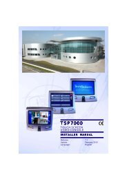
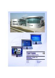
<strong>TSP7000</strong>TOUCH SCREENVIDEO CONSOLEUSER MANUALRelease: 1.1Update: March 2010Language:English
The features of the consol can be subject to change without notice.Unauthorized reproduction or distribution of this manual, or any portion of it, on any deviceand in any form, is prohibited.The contents of this manual may be subject to change without notice.IIUser Manual - <strong>TSP7000</strong>
CONFORMITYHereby, <strong>Tecnoalarm</strong> srl declares that the present equipment is in compliance with the essentialrequirements and other relevant provisions of the LVD 2006/95/EC and EMC 2004/108/ECdirectives.The declaration of conformity is available on the website: www.tecnoalarm.com.<strong>TSP7000</strong> - User ManualIII
PREFACEIMPORTANT NOTESThe use of monitoring devices in some environments can be prohibited by law.The network cameras are devices with high performances ready to function on the web, butthey can also be devices of a flexible surveillance system.The user must ensure that the use of these surveillance devices is permitted and legal beforeproceeding with their installation.WARNINGAll the "WARNING" notes contain important information for the user.To ignore these warnings can be dangerous.IVUser Manual - <strong>TSP7000</strong>
INDEX1. CONSOLE1.1 FRONT VIEW 1-11.2 REVERSE SIDE 1-22. MAIN FEATURES2.1 HARDWARE SPECIFICATIONS 2-12.2 TECHNICAL DATA 2-12.3 MAIN FUNCTIONS 2-23. FUNCTIONS3.1 INITIATION 3-13.2 DIRECT FUNCTIONS 3-23.2.1 Viewing of the single cameras 3-23.2.2 Volume setting 3-33.2.3 Brightness setting 3-33.2.4 Switching the display off/on 3-33.3 FUNCTIONS ACCESSIBLE WITH CODE 3-43.3.1 Access with user code 3-43.3.2 False code 3-53.3.3 Access with biometric sensor 3-53.4 USER MENU 3-63.4.1 Icons 3-63.5 PROGRAMS 3-73.5.1 Arming program 3-83.5.2 Disarming program 3-103.5.3 Total quick arming/disarming of the programs 3-103.6 REMOTE CONTROLS 3-113.6.1 Remote control activation 3-123.6.2 Remote control deactivation 3-133.7 EVENTS 3-143.8 VIEWING OF THE ZONES 3-183.8.1 Voluntary permanent exclusion of a zone 3-193.8.2 Voluntary re-enabling of a zone 3-193.8.3 Viewing of the open zones 3-203.9 CAMERAS 3-213.9.1 Viewing of a camera 3-213.9.2 Viewing of a group of cameras 3-223.10 SETTINGS 3-233.10.1 Volume setting 3-233.10.2 Brightness setting 3-233.10.3 Deletion/extraction of photos from the memory 3-243.10.4 Installation/removal of USB key 3-243.10.5 Enabling of the external monitor output (TV) 3-253.10.6 System information 3-263.11 FINGER PRINTS 3-273.11.1 Finger print reading 3-28<strong>TSP7000</strong> - User Manual 1
3.11.2 Hold-up finger print reading 3-303.12.3 Finger print delation 3-30APPENDIX A - MAINTENANCEA.1 PROTECTION A-3A.2 HOW TO CLEAN THE CASING A-3A.3 HOW TO CLEAN THE TOUCH SCREEN DISPLAY A-32 User Manual - <strong>TSP7000</strong>
1. CONSOLE1.1 FRONT VIEW<strong>TSP7000</strong> - User Manual1-1
1.2 REVERSE SIDE1-2 User Manual - <strong>TSP7000</strong>
2. MAIN FEATURES2.1 HARDWARE SPECIFICATIONS• 10-100 TBase Ethernet input for LAN-WANconnection• RS422 serial bus towards control panel(max. length 1km)• Full speed USB2.0 input to connect a USBkey (flash memory)• 7 inches touch screen display with 65,000colors with resolution 800x480dpi• 3rd generation biometric finger print reader• Temperature probe• PIR of human presence sensor• Internal memory (10,000 photos withstandard memory)• Multifunction RGB LED placed on thebiometric sensor• Standby button• Multicolors cover frame for easy blendingwith home decoration• Power supply: 12V DC or power splitterover Ethernet• Max. consumption 3W2.2 TECHNICAL DATA• Video compression: MPEG-4 SP• Max. resolution: D1 (720x576 dpi)• Network protocols: TCP, FTP, HTTP, RTSP• Video stream: max. 4 streamssimultaneously on the display• Max. 24 cameras controllable by groups of 4• Frame rate:With 4 streams = 8 frames per secondalltogetherWith 1 stream= max. 12 frames persecond• Video mode: D1 (720X576 dpi)VGA (640x480 dpi)QVGA (320x240 dpi)QQVGA (160x120 dpi)3GPP ( 176x144 dpi)• Multilanguage voice synthesis• Loudspeaker volume and display brightnesssettings<strong>TSP7000</strong> - User Manual2-1
2.3 MAIN FUNCTIONS• Viewing of 1 to 4 cameras in standby• Association of the cameras to the zones ofthe control panel• Pop-up on display of the camera inquestion and acoustic signaling in case ofopen zone or zone alarm• Pop-up on display of the photo sequencein case of open zone or zone alarm andacoustic signaling• Pop-up on display of the zone and acousticsignaling in case of open zone or prealarm• Sophisticated console function for controlpanel management (arming/disarming,activations, event viewing etc.)• Energy saving mode after a programmabletimeout• Download of photos onto USB memory stick• Event log with viewing of the events of thecontrol panel + photos• Viewing of photo with event zoom function• PTZ on motorized surveillance cameras(for supported models only)• Recognition of max. 99 finger prints for useridentification• Fake finger detection function(Anti-spoofing)2-2 User Manual - <strong>TSP7000</strong>
3. FUNCTIONS3.1 INITIATIONUpon the first initiation of the console, on thescreen is viewed the beside image.The console is initiated.After initiation (which can require a fewminutes), the stand-by screen is displayed.STAND-BYAccording to the installer programming, thestand-by screen views the following items:• max. 4 video streams• max. 4 customizable function keys• the time of the installation• an icon for loudspeaker volume setting• an icon for display brightness setting• an icon for access with code• the ambient temperatureWARNINGAll of the procedures in the stand-by environment can be executed without anyaccess code.For security reasons, it is recommended to reduce to a minimum the procedureswhich can be executed in this environment in order to avoid that whoever passesby the console has access to private information or can execute confidentialcontrols.<strong>TSP7000</strong> - User Manual3-1
3.2 DIRECT FUNCTIONSWARNINGThe direct functions, i.e. accessible without code, are programmed by the installerduring system configuration.For simplicity reasons, on the following pagesthe most common configuration is analysed.STAND-BY ENVIRONMENTIn stand-by, the console usually shows:• video streams of a variable number ofcameras (1 to 4)• the time (in different formats)• the detected ambient temperature• loudspeaker volume setting icon• display brightness setting iconTime ofthe consoleVolumesettingVolumeoffIdentificationBrightnesssettingTemperature3.2.1 VIEWING OF THE SINGLECAMERASWhen the console is in stand-by, touch one ofthe video streams displayed.3-2 User Manual - <strong>TSP7000</strong>
On the screen is viewed what is being recordedby the selected camera.3.2.2 VOLUME SETTINGTo set the volume of the voice messages of thevideo console, touch the loudspeaker icon thenmove the scroll bar to the value desired.To switch off the volume, touch the crossed-outloudspeaker icon or move the scroll bar to zero.2.2.3 BRIGHTNESS SETTINGTo set the display brightness, touch the bulbicon then move the scroll bar to the desiredvalue.2.2.4 SWITCHING THE DISPLAY OFF/ONPress the button on the lower right hand side ofthe console to switch off the display.The display is switched on again in one of thisfollowing circumstances:• the pressure of the same button• touching the screen with a finger• the passage in front of the infrared humanpresence sensor.<strong>TSP7000</strong> - User Manual3-3
3.3 FUNCTIONS ACCESSIBLE WITH CODEWARNINGThe <strong>TSP7000</strong> video console uses the access codes programmed on the controlpanel to which it is connected.The functions accessible by each user depend on programming of the entered access code.For semplicity reasons, on the following pages a user enabled for all the functions is analysed.Access to the video console functions (user menu) is given by access code or by finger print if learntappropiately).3.3.1 ACCESS WITH USER CODEWhen the console is in stand-by (beside image),touch the key icon.On the screen is viewed the virtual keypad.Enter the user code.CODE NOT RECOGNIZEDIf the composed code is not recognized, theconsole does not execute any operation.CODE RECOGNIZEDIf the composed code is recognized, theconsole gives access to the user menu (besideimage).3-4 User Manual - <strong>TSP7000</strong>
3.3.2 FALSE CODEThe pressure of 32 keys without enter a validecode causes an alarm signaling of false code ofthe <strong>TSP7000</strong> console towards the control panel.When an alarm is detected, on the screen isviewed the beside image, the loudspeaker ofthe console transmits the false code message,the console where the alarme was released isdisabled for 2 minutes and the alarm is recordedin the events memory.WARNINGThe block of the console can be interrupted only by taping a valid user code on another video console or on a keypad connected to the control panel (if present).3.3.3 ACCESS WITH BIOMETRICSENSORIf the finger prints has been already learnt,access in the operative environment of theconsole is possible swiping a finger on thebiometric reader below the display.Learning of the finger prints is done by swipingthe fingertip from the top to the bottom of thereader with a constant speed.It is possible to associate max. 10 finger printsto each user code.LEARNING OKIf the finger print is learnt, the LED of the readeris blinking green and the console gives accessto the user menu.Finger printlearnt(LED green)Finger printnot learnt(LED red)LEARNING FAILEDIf the finger print is not learnt, the LED of thereader is blinking red and and the console doesnot permit any procedure -Access denied.<strong>TSP7000</strong> - User Manual3-5
3.4 USER MENUOn the display are viewed only the functions associated to the entered code or the finger print learnt.The following functions are available:• Programs Arming/disarming and viewing of alarms relating to the programsassociated to the code• Total quick arming Simultaneous total arming of all programs associated to the code• Total quick disarming Simultaneous total disarming of all programs associated to the code• Remote controls Activation/deactivation of the remote controls associated to the code• Events Viewing of the events detected by the control panel and recorded bythe video console (arming/disarming, alarms, photos etc.)• Zones Viewing of the current status, permanent exclusion of the zone,viewing of the events relating to the zone• Cameras Viewing of the images recorded in real-time by the selected camera orby the cameras (group of 4)• Settings Setting of the loudspeaker volume and display brightness, cancellingof the recorded events from the memory, copying of the events ontoUSB memory sticks, activation of the external monitor output (TV)• Finger prints Recording of the finger prints3.4.1 ICONSNAVIGATION ICONSThe following icons are usualy viewed on the right hand side of the display and permit navigation of themenus of the <strong>TSP7000</strong> video console.Quit and returnto the previousenvironmentQuit and returnto stand-byQuickupwardscrollUpwardscrollQuickdownwardscrollDownwardscrollFUNCTION ICONSThe following icons are viewed in different operating environments and are normally viewed on bothsides of the display:Viewingof thecameraLoudspeakervolumesettingDisplaybrightnesssettingTroublesignalEvent withvideo stream+ namecameraProcedurerunningWaitProcedurerunningWait3-6 User Manual - <strong>TSP7000</strong>
3.5 PROGRAMSTouch Programs to enter this environment.On the display are viewed all the programsassociated to the user in question(e.g. program 1 and 2 ).For each program the following information aredisplayed:• Status and name• Program alarm memorySTATUS AND NAMENumber (e.g. 2) and name (e.g. Dualtecno)associated to the program.The program status is viewed by the statusindicators and by the color.Status indicatorsDisarming(grey)Arming(yellow)Alarmrunning(red)Disarmingwith alarmmemoryArming withalarm memoryBy-passBy-pass withalarm memoryColorIf the program icon (e.g. program 1) is viewedwith a dark blue color, the program is armed.If the program icon (e.g. program 1) is viewedwith a clear blue color, the program isdisarmed (stand-by).PROGRAM ALARM MEMORYThe bell is viewed on the right hand side andsignals that a program alarm has been detected.Touch the bell to view the alarms releasedduring the last arming period.Program alarmmemory (yellow)No alarmmemorized(grey)<strong>TSP7000</strong> - User Manual3-7
3.5.1 PROGRAM ARMINGTouch the program to be armed.On the screen is viewed the beside image.Commands available• YES to arm the program• NO to abandon• Voluntary zone exclusionTo select the zone to be excluded3.5.1.1 VOLUNTARY ZONE EXCLUSIONBefore completion of program arming it ispossible to voluntarily exclude zones from thedetection of alarms.Touching voluntary zone exclusion on thescreen is viewed the beside image.Touch the zone to be excluded (e.g. zone 1).The color of the selected zone becames darkblue.Repeat the same procedure for all the zones tobe excluded.Commands available• PROCEED to confirm the voluntary zoneexclusion• EXIT to abandon3-8 User Manual - <strong>TSP7000</strong>
Touching Proceed, on the screen is viewed thebeside image.Commands available• YES to confirm arming of the programwith exclusion of the zones viewed• NO to abandonConfirming program arming, on the screen isviewed the beside image.Once the time displayed has elapsed, theselected program is armed.On the screen is viewed the beside image.The icon corresponding to the program inquestion is blinking and the status indicator (thepadlock symbol) changes between the openand closed condition during the entire exit timeof the control panel (i.e. arming phase).When the program is armed, the padlock isclosed and the color of the zone icon is darkblue.The voice synthesis announces all theprocedure executed.<strong>TSP7000</strong> - User Manual3-9
3.5.2 PROGRAM DISARMINGTouch the program to be disarmed.On the screen is viewed the beside image.Commands available• YES to disarm the program• NO to abandonConfirming the disarming, on the screen isviewed the beside image.The voice synthesis announces all theprocedure executed.3.5.3 TOTAL QUICK ARMING/DISARMINGOF THE PROGRAMSTouch the padlock icon to activate the total quickarming/disarming function.TOTAL QUICK ARMING(Yellow and closed padlock icon)The total quick arming icon permits to arm all theprograms associated to the code entered withan unique procedure.The voice synthesis communicates all theprocedure executed.TOTAL QUICK DISARMING(Grey and open padlock icon)The total quick disarming icon permits to disarmall the programs associated to the code enteredwith an unique procedure.The voice synthesis communicates all theprocedure executed.3-10 User Manual - <strong>TSP7000</strong>
3.6 REMOTE CONTROLSTouch Remote controls to enter thisenvironment.On the screen are viewed all the remotecontrols associated to the user in question.For each remote control is shown:• Status and nameSTATUS AND NAMENumber and name associated to the remotecontrol.The status of the remote control is viewed bythe status indicators and by the color.Remote controlactive (LED red)Remote control instand-by (LED grey)Status indicatorsIf the LED in the switch icon is red, the remotecontrol is active.If the LED in the switch icon is grey, the remotecontrol is in stand-by.ColorIf the remote control icon is viewed with a darkblue color, the remote control is active.If the remote control icon is viewed with a clearblue color, the remote control is not active(in stand-by)<strong>TSP7000</strong> - User Manual3-11
3.6.1 REMOTE CONTROL ACTIVATIONTouch the remote control to activate(e.g. remote control 1).On the screen is viewed the beside image.Commands available• YES to activate the remote control• NO to abandonConfirming the activation of the remote control(e.g. remote control 1) on the screen is viewedthe beside image.The circle icon on the left is viewed while theactivation procedure is running.Wait until the procedure has been completed.Once the procedure has been completed, theremote control in question (e.g. remote control 1)is active.The active remote controls are viewed with adifferent color (i.e. dark blue).3-12 User Manual - <strong>TSP7000</strong>
3.6.2 REMOTE CONTROL DEACTIVATIONTouch the remote control to deactivate(e.g. remote control 1).On the screen is viewed the beside image.Commands available• YES to deactivate the remote control• NO to abandonThe circle icon on the left is viewed while thedeactivation procedure is running.Wait until the procedure has been completed.Once the procedure has been completed, theremote control in question (e.g. remote control 1)is deactivated.<strong>TSP7000</strong> - User Manual3-13
3.7 EVENTSTouch Events to enter this environment.On the screen are viewed all the events registered in the memoryof the console and associated to the code composed or to thedetected finger print.Each icon represents a different type of event:End ofalarm (grey)Beginningof alarm(yellow)Hold-upalarmProgramdisarmingProgramarmingProgramby-passEvent withvideo stream +name cameraActivationof remotecontrol(LED red)Deactivation ofremote control(LED grey)Exclusionof zoneReactivationof excludedzoneInstallereventsThe Installer events icon permits viewing of all the accessoperations with codes/finger print which are normally hidden inthe event environment.3-14 User Manual - <strong>TSP7000</strong>
The date and time of the recorded event and thedescription are always viewed for each event,e.g.:Alarm Zone 1Automatic disarming program 2Event with photos registered by the camera 1Touching an event, it is possible to view theadditional information (if present) or to view thevideo stream to this event.ZONE ALARMFor each zone alarm, date and time of the eventas well as the zone name is shown.AUTOMATIC DISARMING OF PROGRAM 2ARMING BY USER 3<strong>TSP7000</strong> - User Manual3-15
EVENTWITH VIDEO STREAMEventA sequence of 8 photos is associated to each of these events.• The 4th photo of the first line shows the event which has released the alarm.• The first 3 photos show the situation recorded by the camera during the seconds right before theevent.• The 4 photos of the second line show the situation recorded by the camera during the secondsright after the event.Touch one of this photos to view it in the full screen mode.3-16 User Manual - <strong>TSP7000</strong>
Commands availableDigital zoom in of the image (+)Digital zoom out of the image (-)Return to the standard size of the imageNAVIGATION OF THE EVENT LOGThe events are viewed in chronological order starting from the newest event.Navigate the event list using the below up and down arrows or simply scrolling the screen from the topto the bottom or vice et versa with a finger.The events are listed in order of date and time.Touch the screen again in order to stop scrolling.NAVIGATION ICONSQuickupwardscrollUpwardscrollQuickdownwardscrollDownwardscroll<strong>TSP7000</strong> - User Manual3-17
3.8 VIEWING OF THE ZONESTouch Zones to enter this environment.All the zones of the control panel are viewed.Each zone shows the following information:• Status and name• Zone alarm memorySTATUS AND NAMENumber and the name associated to the zone aswell as its status.The zone status is shown by the statusindicators and by the color.Status indicatorsClosed zone(grey)Open zone(red)Excluded zoneExclusion orenablingprocedure runningColor• Open zoneTrouble signaling.The open zone is viewed with a dark bluecolor.• Closed zoneOK.The closed zone is viewed with a clear bluecolor.• Excluded zoneDefines that the zone is voluntarily excludedfrom the alarm detection.ALARM ZONE MEMORYThe bell is viewed on the right hand side andsignals that a zone alarm has been detected.Touch the bell to view the alarms releasedduring the last arming period.Alarm memory.Zone alarmdetected (yellow))No alarmmemorised(grey)3-18 User Manual - <strong>TSP7000</strong>
3.8.1 VOLUNTARY PERMANENTEXCLUSION OF A ZONETouch the zone to be excluded (e.g. zone 1).On the screen is viewed the beside image.Commands available• YES to confirm the permanent exclusionof the zone• NO to abandonConfirming the zone exclusion, on the screen isviewed the beside image.The circle icon on the left is viewed while theexclusion procedure is running.Wait till the procedure has been completed andthe beside image is displayed.The crossed circle icon on the left indicates thatthe zone has been excluded.WARNINGThe zone is excluded (not controlled by the control panel) until it is voluntarilyincluded by the user.The procedure of permanent exclusion of the zones must to be enabled by theinstaller during the system configuration.3.8.2 VOLUNTARY RE-ENABLING OF AZONETouch the zone to enable it again (e.g. zone 1).On the screen is viewed the beside image.Commands available• YES to confirm the permanent inclusionof the zone• NO to abandonConfirming the zone inclusion, on the screen isviewed the beside image.The grey circle icon on the left indicates that thezone is included again (i.e. is actived).<strong>TSP7000</strong> - User Manual3-19
3.8.3 VIEWING OF THE OPEN ZONESTouch the Zone status icon (red circle) on the right hand side to view the open zones only.All the open zones are viewed.This environment permits:• Exclusion of one of the open zonesTouch the zone to be excluded and follow the procedure § 3.8.1• Viewing of the alarm memory of the selected zoneTouch the bell to view the alarms memorised for the selected zone.3-20 User Manual - <strong>TSP7000</strong>
3.9 CAMERASTouch Cameras to enter this environment.On the screen is viewed:All the cameras controlled by the control panelare displayed by groups of 4.NAME OF THE CAMERAThe number and the name associated to thecamera is shown in the corresponding box ofeach camera.The beside icon is shown in the center of eachgroup of 4.3.9.1 VIEWING OF A CAMERATouch the icon corresponding to the camera toview.<strong>TSP7000</strong> - User Manual3-21
On the screen is shown what has beenrecorded by the selected camera.3.9.2 VIEWING OF A GROUP OFCAMERASTouch the camera group icon to be select.On the screen is viewed what has beenrecorded by the selected group of cameras.3-22 User Manual - <strong>TSP7000</strong>
3.10 SETTINGSTouch Settings to enter this environment.WARNINGThe Settings function is displayed only if enabled by the installer upon systemconfiguration.3.10.1 VOLUME SETTINGFollow the procedure of § 3.2.2WARNINGThe installer can enable/disable this function with the icons and always displaythem when the console is in stand-by.3.10.2 BRIGHTNESS SETTINGFollow the procedure of § 3.2.3WARNINGThe installer can enable/disable this function with the icons and always displaythem when the console is in stand-by.<strong>TSP7000</strong> - User Manual3-23
3.10.3 DELETION/EXTRACTION OF PHOTOS FROM THE MEMORYWARNINGThis function can be enabled/disabled by the installer.The photos deleted from the memory cannot be recovered.Always act with prudence before deletion.All the photos recorded after an alarm are stored in the memory of the console.This memory is slowly filled.When the memory is almost full, the installation automatically deletes the oldest photos in order to storethe latest events.See the deletion procedure to voluntarily delete part of the memory.Touch the beside icon to enter the photomemory.On the screen is viewed the beside image.DELETIONTouch the basket icon to delete the photosstored in the memory starting from the oldestone.COPYTouch the USB icon to copy the photos onto theUSB key starting from the oldest one.3.10.4 INSTALLATION / REMOVAL OFUSB KEYWARNINGThe USB key must be installed on the system before use.To avoid data loss, always uninstall the USB key with the correct procedurebefore you remove it. Otherwise all the data will be lost.INSTALLATION OF USB KEYTouch the USB icon.On the screen is viewed the beside image.Insert the USB key into the USB port.Touch Proceed to continue the installationprocedure of the USB key.3-24 User Manual - <strong>TSP7000</strong>
Once the installation has been completed, on thescreen is viewed the beside image.The USB key is ready for use.The remaining storage capacity is viewed.REMOVAL OF USB KEYTouch the USB icon.On the screen is viewed the beside image.Touch Proceed to continue the uninstallprocedure of the USB key.Once the key has been uninstalled, on thescreen is viewed:the USB key can be removed.3.10.5 ENABLING OF THE EXTERNALMONITOR OUTPUT (TV)Touch the TV-OUT icon to enable the externalmonitor output.The status of the external monitor output isviewed by the status indicators.Status indicatorsExternal monitor output enable, i.e. active(Audio + Video)External monitor output disable, i.e. not active<strong>TSP7000</strong> - User Manual3-25
3.10.6 SYSTEM INFORMATIONTouch Info to enter this environment.On the screen is viewed the image here below.On the screen are viewed all the information about the system:Video console• Name of the product <strong>TSP7000</strong>• Name of the producer <strong>Tecnoalarm</strong>• Firmware version 0.3 beta• Date/hour of release 19/06/09 - 13:40Biometric finger print reader• Firmware version• Type reader3-26 User Manual - <strong>TSP7000</strong>
3.11 FINGER PRINTSTouch Finger prints to enter this environment.WARNINGThe Finger prints function is viewed only if previously enabled by the installerduring the system configuration.On the screen is viewed the beside image.In the upper part are displayed all the optionsavailable in this environment.Touch the command bar until the desired one isdisplayed.Options available• Reading of finger prints for the selectedcode• Reading of "hold-up" finger prints for theselected code• Deletion of finger prints for the selectedcodeNAME OF THE CODEThe number (xx) and the name (yyyyyyy)associated to the code are viewed at the end ofthe description.FINGER PRINTS ASSOCIATED TO THE CODEIt is possible to associate max. 10 finger printsto each code (i.e. one finger print for eachfinger).If the finger print is memorised, it is greencolored (e.g. fingers 6 and 7 on the besideimage).If the finger print is not memorised, it is grey.<strong>TSP7000</strong> - User Manual3-27
3.11.1 FINGER PRINT READINGTouch Reading of finger prints code x - y tostart the procedure.On the screen is viewed the beside image.Touch the icon corresponding to the finger printto be acquired (number 1 to 10).On the screen is viewed the beside image.Commands available• YES to start the reading procedure of theselected finger print• NO to abandonConfirming the start of the reading procedure,on the screen is viewed the beside image.Reading of the finger print happens by swipinga finger (e.g. finger 7 in the beside image) fromthe top to the bottom of the reader.3-28 User Manual - <strong>TSP7000</strong>
WARNINGThe system asks to repeat the finger print reading procedure 5 times (another4 times).This procedure permits an exact recognition of the finger print in the most of theoperating conditions.Swip the finger all the times the systemrequires it.Repeat until the 5th correct reading.After 5 correct readings, the systemrecords the finger print corresponding to theselected finger (e.g. finger 7).The recorded finger print is viewed with agreen color as indicated by the besideimage.From this moment onwards, the usercorresponding to the code 3 (e.g. Mario) canuse the finger print of the recorded finger(e.g. finger 7) to access the functionsassociated to its code without compose itsaccess code.<strong>TSP7000</strong> - User Manual3-29
3.11.2 HOLD-UP FINGER PRINTREADINGThe hold-up finger print corresponds to thehold-up code composed on the control panel.This generates a silent alarm signaling (silentalarm) towards the control panel.Touch Reading of "hold-up" finger printscode x - y.On the screen is viewed the beside image.Follow the procedure § 3.12.1Once the acquisition has been completed, theuser 3 (e.g. Mario) can use the selected fingerprint to release an hold-up alarm, if necessary.3.11.3 FINGER PRINT DELATIONThe Finger prints delation function permits todelete the finger print already recorded for theselected finger.Touch Deletion of finger prints code x - y.On the screen is viewed the beside image.Touch the icon corresponding to the finger printto delete (it must be green colored).On the screen is viewed the beside image.Commands available• YES to confirm deletion of the finger printof the selected finger• NO to abandon3-30 User Manual - <strong>TSP7000</strong>
APPENDIX AMAINTENANCE<strong>TSP7000</strong> - User ManualA-1
A-2 User Manual - <strong>TSP7000</strong>
A. MAINTENANCEA.1 PROTECTIONIn order to avoid permanent damages, do not install the <strong>TSP7000</strong> video console in environments inwhich it could be exposed to high temperatures for a long period of time.Prevent the <strong>TSP7000</strong> video console from having contact with water or detergents as humidily couldcompromise the smooth functionning of the device.A.2 HOW TO CLEAN THE CASINGThe <strong>TSP7000</strong> console is built using high quality materials and maintenance of the device requires somesimple cleaning procedures.To clean the casing (touch screen display excluded) use a soft and clean cloth, humidified with anon-aggressive detergent, then dry carefully in order to avoid that humidily enters by the slots of thecasing.Do not use chemical detergents and solvents which can damage the parts in plastic.Do not use specific glasse or mirror cleaners nor any other types of detergent, spray, solvent, alcool,ammonia or abrasive.A.3 HOW TO CLEAN THE TOUCH SCREEN DISPLAYClean the touch screen display with a soft and clean cloth.Use water, isopropanol alcool or, if necessary, a glass and lens cleaner.Apply the liquid on the cloth and delicately clean the touch screen display.WARNINGFor the maintenance of the display, use a non-corrosive and non-abrasiveproduct, specifically designed for LCD displays or a glass cleaner.Prevent the liquid from entering the casing by the slots.<strong>TSP7000</strong> - User ManualA-3
<strong>TSP7000</strong>USER MANUALA-4 User Manual - <strong>TSP7000</strong>