Accessing the Network Camera - Tecnoalarm
Accessing the Network Camera - Tecnoalarm
Accessing the Network Camera - Tecnoalarm

Create successful ePaper yourself
Turn your PDF publications into a flip-book with our unique Google optimized e-Paper software.
VIVOTEKTable of ContentsOverview3Read Before Use3Package Contents3Physical Description4Cabling Assembly5Hardware Installation7<strong>Network</strong> Deployment 11Software Installation13Ready to Use14Adjusting <strong>the</strong> Lens14Completion15<strong>Accessing</strong> <strong>the</strong> <strong>Network</strong> <strong>Camera</strong> 16Using Web Browsers16Using RTSP Players18Using 3GPP-compatible Mobile Devices19Using VIVOTEK Recording Software20Main Page 21Client Settings 24Configuration 26System27Security29HTTPS30SNMP35<strong>Network</strong>36DDNS50Access List52Video55Motion Detection61<strong>Camera</strong> Tampering Detection 63Homepage Layout64Application67Recording80Local Storage83System Log87View Parameters88Maintenance89Appendix 93URL Commands for <strong>the</strong> <strong>Network</strong> <strong>Camera</strong>93Technical Specifications132Technology License Notice133Electromagnetic Compatibility (EMC)1342 - User's Manual
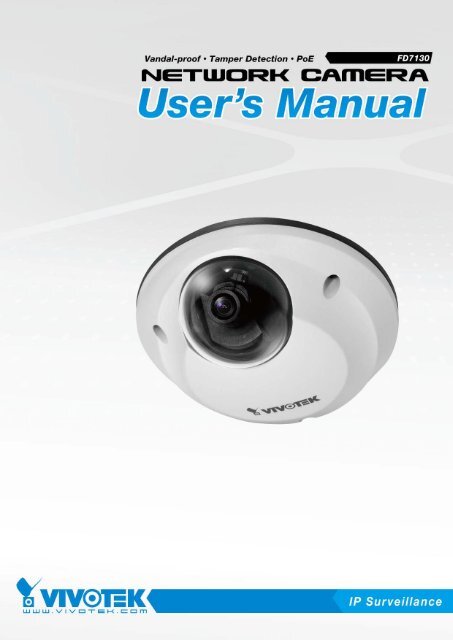
VIVOTEKOverviewThe VIVOTEK FD7130 is a flat compact, dome type network camera, designed for <strong>the</strong> toughenvironmental conditions, especially in such public transportation as buses, trains, etc. Its IP66-rated,vandal-proof metal housing effectively provides robust protection from being damaged by water anddusts as well as vandalism. In compliance with EN50155, a standard for electronic equipment operatingin railway vehicles, FD7130 is an economical mobile surveillance solution packed with high reliability andrugged performance.With <strong>the</strong> support of tamper detection, FD7130 becomes an intelligent camera, keeping security staffnotified at all time once it suffers video loss from being blocked or spray-painted. FD7130 utilizes Powerover E<strong>the</strong>rnet (PoE), allowed to be operated and powered from a single cable, relatively giving greaterease of installation and cost savings. In order to facilitate on-board storage and data portability, FD7130also provides a MircoSD/SDHC card slot for temporary recording.FD7130 also offers a broad spectrum of advanced features including simultaneous dual streams, QoSfor optimized bandwidth efficiency, IPv6 for next generation networks, temperature alarm trigger, HTTPSencrypted data transmission and 802.1X au<strong>the</strong>ntication for network protection.Read Before UseThe use of surveillance devices may be prohibited by law in your country. The <strong>Network</strong> <strong>Camera</strong> is notonly a high-performance web-ready camera but can also be part of a flexible surveillance system. It is<strong>the</strong> user’s responsibility to ensure that <strong>the</strong> operation of such devices is legal and complies with all privacylaws before installing this unit for its intended use.It is important to first verify that all contents received are complete according to <strong>the</strong> Package Contentslisted below. Take note of <strong>the</strong> warnings in <strong>the</strong> Quick Installation Guide before <strong>the</strong> <strong>Network</strong> <strong>Camera</strong> isinstalled; <strong>the</strong>n carefully read and follow <strong>the</strong> instructions in <strong>the</strong> Installation chapter to avoid damage due tofaulty assembly and installation. This also ensures <strong>the</strong> product is used properly as intended.The <strong>Network</strong> <strong>Camera</strong> is a network device and its use should be straightforward for those who have basicnetworking knowledge. It is designed for various applications including video sharing, general security/surveillance, etc. The Configuration chapter suggests ways to best utilize <strong>the</strong> <strong>Network</strong> <strong>Camera</strong> andensure proper operations. For more creative and professional developers, <strong>the</strong> URL Commands of <strong>the</strong><strong>Network</strong> <strong>Camera</strong> section serves as a helpful reference to customizing existing homepages or integratingwith <strong>the</strong> current web server.Package Contents■ FD7130 with an RJ45 or M12 Cable■ Liquid Tight Connectors for RJ45 or M12 Cable■ Software CD■ Alignment Sticker■ Quick Installation Guide / Warranty Card■ Ground Wire / Screws■ Screwdriver■ Silica Gel / Clamp CoreUser's Manual - 3
VIVOTEKWall Mount12BA3Please secure <strong>the</strong> screws tightly toavoid moisture.4Installing <strong>the</strong> Ground WireAs shown in <strong>the</strong> following figure, please secure one side of <strong>the</strong> supplied ground wire to <strong>the</strong>screw hole, <strong>the</strong>n route <strong>the</strong> o<strong>the</strong>r side of <strong>the</strong> ground wire to <strong>the</strong> ground.8 - User's Manual
LINKRECEIVELINKRECEIVEPARTITIONVIVOTEKSet up <strong>the</strong> <strong>Network</strong> <strong>Camera</strong> through Power over E<strong>the</strong>rnet (PoE)When using a PoE-enabled switchThe <strong>Network</strong> <strong>Camera</strong> is PoE-compliant, which allows it to be powered via a single E<strong>the</strong>rnetcable. If your switch/router supports PoE, refer to <strong>the</strong> following illustration to connect <strong>the</strong><strong>Network</strong> <strong>Camera</strong> to a PoE-enabled switch/router.power + data transmissionPOWER COLLISION1 2 3 4 5PARTITIONPoE SwitchWhen using a non-PoE switchIf your switch/router does not support PoE, use a PoE power injector (optional) to connect <strong>the</strong><strong>Network</strong> <strong>Camera</strong> and a non-PoE switch/router.PoE Power Injector(optional)POWER COLLISION1 2 3 4 5Non-PoE Switch10 - User's Manual
POWER CO LISION1 2 3 4 5LINKRECEIVEPARTITIONVIVOTEK<strong>Network</strong> DeploymentSetting up <strong>the</strong> <strong>Network</strong> <strong>Camera</strong> over <strong>the</strong> InternetThere are several ways to set up <strong>the</strong> <strong>Network</strong> <strong>Camera</strong> over <strong>the</strong> Internet. The first way is to setup <strong>the</strong> <strong>Network</strong> <strong>Camera</strong> behind a router. The second way is to utilize a static IP. The third way isto use PPPoE.Internet connection via a routerBefore setting up <strong>the</strong> <strong>Network</strong> <strong>Camera</strong> over <strong>the</strong> Internet, make sure you have a router and follow<strong>the</strong> steps below.1. Connect your <strong>Network</strong> <strong>Camera</strong> behind a router, <strong>the</strong> Internet environment is illustrated below.Regarding how to obtain your IP address, please refer to Software Installation on page 13 fordetails.InternetWAN (Wide Area <strong>Network</strong> )Router IP address : from ISPIP address : 192.168.0.3Subnet mask : 255.255.255.0Default router : 192.168.0.1LAN (Local Area <strong>Network</strong>)Router IP address : 192.168.0.1Cable or DSL ModemIP address : 192.168.0.2Subnet mask : 255.255.255.0Default router : 192.168.0.12. In this case, if <strong>the</strong> Local Area <strong>Network</strong> (LAN) IP address of your <strong>Network</strong> <strong>Camera</strong> is192.168.0.3, please forward <strong>the</strong> following ports for <strong>the</strong> <strong>Network</strong> <strong>Camera</strong> on <strong>the</strong> router.■ HTTP port■ RTSP port■ RTP port for audio■ RTCP port for audio■ RTP port for video■ RTCP port for videoIf you have changed <strong>the</strong> port numbers on <strong>the</strong> <strong>Network</strong> page, please open <strong>the</strong> ports accordinglyon your router. For information on how to forward ports on <strong>the</strong> router, please refer to yourrouter’s user’s manual.3. Find out <strong>the</strong> public IP address of your router provided by your ISP (Internet Service Provider).Use <strong>the</strong> public IP and <strong>the</strong> secondary HTTP port to access <strong>the</strong> <strong>Network</strong> <strong>Camera</strong> from <strong>the</strong>Internet. Please refer to <strong>Network</strong> Type on page 36 for details.User's Manual - 11
VIVOTEKInternet connection with static IPChoose this connection type if you are required to use a static IP for <strong>the</strong> <strong>Network</strong> <strong>Camera</strong>.Please refer to LAN on page 36 for details.Internet connection via PPPoE (Point-to-Point over E<strong>the</strong>rnet)Choose this connection type if you are connected to <strong>the</strong> Internet via a DSL Line. Please refer toPPPoE on page 37 for details.12 - User's Manual
VIVOTEKReady to Use1. Access <strong>the</strong> <strong>Network</strong> <strong>Camera</strong> from <strong>the</strong> LAN.2. Retrieve live video through a web browser or recording software.Adjusting <strong>the</strong> LensTo adjust <strong>the</strong> viewing angleAdjust <strong>the</strong> lens to a desired viewing angle as <strong>the</strong> diagram shown below.10° 10° 90°DO NOT over rotate <strong>the</strong> lens. Doing sowill damage <strong>the</strong> camera lens module.14 - User's Manual
VIVOTEKFine-tune <strong>the</strong> <strong>Camera</strong> FocusThe focus of this network camera is set from 1.0m to infinity by factory default. If you want tofocus on objects closer than 1.0m or <strong>the</strong> lens has lost focus, please fine tune it in <strong>the</strong> followingway.1. Loosen <strong>the</strong> lens lock screw.2. Manually rotate <strong>the</strong> lens to fine-tune <strong>the</strong> focus until <strong>the</strong> live image is clear.3. Tighten <strong>the</strong> lens lock screw.CompletionTighten <strong>the</strong> lens lock screw.Tear down <strong>the</strong> aluminum foil vacuum bag and take out <strong>the</strong> silica gel. Attach <strong>the</strong> supplied silicagel to <strong>the</strong> inner side of <strong>the</strong> <strong>Network</strong> <strong>Camera</strong>. (Please replace <strong>the</strong> silica gel with a new one if youopen <strong>the</strong> back cover after installation.)Buckle <strong>the</strong> supplied clamp core onto <strong>the</strong> RJ45 or M12 cable to against <strong>the</strong> EMI radiation.Attach <strong>the</strong> dome cover to camera. Secure <strong>the</strong> dome screws with <strong>the</strong> supplied screwdriver.Finally, make sure all parts of <strong>the</strong> camera are securely installed.Please secure <strong>the</strong> screws tightly toprevent <strong>the</strong> cabling against moisture.User's Manual - 15
VIVOTEK<strong>Accessing</strong> <strong>the</strong> <strong>Network</strong> <strong>Camera</strong>This chapter explains how to access <strong>the</strong> <strong>Network</strong> <strong>Camera</strong> through web browsers, RTSP players,3GPP-compatible mobile devices, and VIVOTEK recording software.Using Web BrowsersUse Installation Wizard 2 (IW2) to access to <strong>the</strong> <strong>Network</strong> <strong>Camera</strong>s installed on <strong>the</strong> LAN.If your network environment is not a LAN, follow <strong>the</strong>se steps to access <strong>the</strong> <strong>Network</strong> <strong>Camera</strong>:1. Launch your web browser (eg. Microsoft ® Internet Explorer, Mozilla Firefox, or Netscape).2. Enter <strong>the</strong> IP address of <strong>the</strong> <strong>Network</strong> <strong>Camera</strong> in <strong>the</strong> address field. Press Enter.3. The live video will be displayed in your web browser.4. If this is <strong>the</strong> first time installing <strong>the</strong> VIVOTEK network camera, an information bar will pop upas shown below. Follow <strong>the</strong> instructions to install <strong>the</strong> required plug-in on your computer.NOTE► For Mozilla Firefox or Netscape users, your browser will use Quick Time to stream <strong>the</strong> livevideo. If you donn’t have Quick Time on your computer, please install it first, <strong>the</strong>n launch <strong>the</strong>web browser.16 - User's Manual
VIVOTEK► By default, <strong>the</strong> <strong>Network</strong> <strong>Camera</strong> is not password-protected. To prevent unauthorized access,it is highly recommended to set a password for <strong>the</strong> <strong>Network</strong> <strong>Camera</strong>. For more informationabout how to enable password protection, please refer to Security on page 29.► If you see a dialog box indicating that your security settings prohibit running ActiveX ®Controls, please enable <strong>the</strong> ActiveX ® Controls for your browser.1. Choose Tools > Internet Options > Security > Custom Level.2. Look for Download signed ActiveX ® controls; select Enable or Prompt. Click OK.3. Refresh your web browser, <strong>the</strong>n install <strong>the</strong> Active X ® control. Follow <strong>the</strong> instructions tocomplete installation.User's Manual - 17
VIVOTEKUsing RTSP PlayersTo view <strong>the</strong> MPEG-4 streaming media using RTSP players, you can use one of <strong>the</strong> followingapplications that support RTSP streaming.Quick Time PlayerReal PlayerVLC media player1. Launch <strong>the</strong> RTSP player.2. Choose mpegable File > Open Player URL. A URL dialog box will pop up.3. The address format is rtsp://:/As most ISPs and players only allow RTSP streaming through port number 554, please set <strong>the</strong>RTSP port to 554. For more information, please refer to RTSP Streaming on page 48.For example:rtsp://192.168.5.151:554/live.sdp4. The live video will be displayed in your player.For more information on how to configure <strong>the</strong> RTSP access name, please refer to RTSPStreaming on page 48 for more details.Video 16:38:01 2008/01/0318 - User's Manual
VIVOTEKUsing 3GPP-compatible Mobile DevicesTo view <strong>the</strong> streaming media through 3GPP-compatible mobile devices, make sure <strong>the</strong> <strong>Network</strong><strong>Camera</strong> can be accessed over <strong>the</strong> Internet. For more information on how to set up <strong>the</strong> <strong>Network</strong><strong>Camera</strong> over <strong>the</strong> Internet, please refer to Setting up <strong>the</strong> <strong>Network</strong> <strong>Camera</strong> over <strong>the</strong> Internet onpage 11.To utilize this feature, please check <strong>the</strong> following settings on your <strong>Network</strong> <strong>Camera</strong>:1. Because most players on 3GPP mobile phones do not support RTSP au<strong>the</strong>ntication, makesure <strong>the</strong> au<strong>the</strong>ntication mode of RTSP streaming is set to disable.For more information, please refer to RTSP Streaming on page 48.2. As <strong>the</strong> <strong>the</strong> bandwidth on 3G networks is limited, larger video sizes are not available. Pleaseset <strong>the</strong> video and audio streaming parameters as listed below.For more information, please refer to Video on page 55.Video ModeMPEG-4Frame size 176 x 144Maximum frame rate5 fpsIntra frame period1SVideo quality (Constant bit rate) 40kbpsAudio type (GSM-AMR)12.2kbps3. As most ISPs and players only allow RTSP streaming through port number 554, please set<strong>the</strong> RTSP port to 554. For more information, please refer to RTSP Streaming on page 48.4. Launch <strong>the</strong> player on <strong>the</strong> 3GPP-compatible mobile device (ex. Real Player).5. Type <strong>the</strong> following URL command into <strong>the</strong> player:rtsp://:/.For example:rtsp://192.168.5.151:554/live.sdpUser's Manual - 19
VIVOTEKUsing VIVOTEK Recording SoftwareThe product software CD also contains VIVOTEK’s recording software, allowing simultaneousmonitoring and video recording for multiple <strong>Network</strong> <strong>Camera</strong>s. Please install <strong>the</strong> recordingsoftware, <strong>the</strong>n launch <strong>the</strong> program to add <strong>the</strong> <strong>Network</strong> <strong>Camera</strong> to <strong>the</strong> Channel list. For detailedinformation about how to use <strong>the</strong> recording software, please refer to <strong>the</strong> user’s manual of <strong>the</strong>software or download <strong>the</strong> manual from http://www.vivotek.com.20 - User's Manual
VIVOTEKMain PageThis chapter explains <strong>the</strong> layout of <strong>the</strong> main page. It is composed of <strong>the</strong> following sections:VIVOTEK INC. Logo, Host Name, <strong>Camera</strong> Control Area, Configuration Area, Menu, and LiveVideo Window.VIVOTEK INC. Logo<strong>Camera</strong> Control AreaHost NameConfiguration AreaLive View WindowVIVOTEK INC. LogoClick this logo to visit <strong>the</strong> VIVOTEK website.Host NameThe host name can be customized to fit your needs. For more information, please refer to System on page27.<strong>Camera</strong> Control AreaVideo Stream: This <strong>Network</strong> Cmera supports MJPEG or MPEG-4 dual streams simultaneously. You canselect ei<strong>the</strong>r one for live viewing.Configuration AreaClient Settings: Click this button to access <strong>the</strong> client setting page. For more information, please refer toClient Settings on page 24.Configuration: Click this button to access <strong>the</strong> configuration page of <strong>the</strong> <strong>Network</strong> <strong>Camera</strong>. It is suggestedthat a password be applied to <strong>the</strong> <strong>Network</strong> <strong>Camera</strong> so that only <strong>the</strong> administrator can configure <strong>the</strong><strong>Network</strong> <strong>Camera</strong>. For more information, please refer to Configuration on page 26.Language: Click this button to choose a language for <strong>the</strong> user interface. Language options are availablein: English, Deutsch, Español, Français, Italiano, 日 本 語 , Português, 簡 体 中 文 , and 繁 體 中 文 .User's Manual - 21
VIVOTEKLive Video Window■ The following window is displayed when <strong>the</strong> video mode is set to MPEG-4:MPEG-4 Protocol and Media OptionsVideo TitleTitle and Time Video 18:55:53 2009/04/27TimeVideo Control ButtonsVideo Title: The video title can be configured. For more information, please refer to Video Settings onpage 55.MPEG-4 Protocol and Media Options: The transmission protocol and media options for MPEG-4 videostreaming. For fur<strong>the</strong>r configuration, please refer to Client Settings on page 24.Time: Display <strong>the</strong> current time. For fur<strong>the</strong>r configuration, please refer to Video Settings on page 55.Title and Time: The video title and time can be stamped on <strong>the</strong> streaming video. For fur<strong>the</strong>r configuration,please refer to Video Settings on page 55.Video Control Buttons: Depending on <strong>the</strong> <strong>Network</strong> <strong>Camera</strong> model and <strong>Network</strong> <strong>Camera</strong> configuration,some buttons may not be available.Snapshot: Click this button to capture and save still images. The captured images will be displayedin a pop-up window. Right-click <strong>the</strong> image and choose Save Picture As to save it in JPEG (*.jpg) or BMP(*.bmp) format.Digital Zoom: Click and uncheck “Disable digital zoom” to enable <strong>the</strong> zoom operation. The navigationscreen indicates <strong>the</strong> part of <strong>the</strong> image being magnified. To control <strong>the</strong> zoom level, drag <strong>the</strong> slider bar. Tomove to a different area you want to magnify, drag <strong>the</strong> navigation screen image.Pause: Pause <strong>the</strong> transmission of <strong>the</strong> streaming media. The button becomes <strong>the</strong>after clicking <strong>the</strong> Pause button.Resume buttonStop: Stop <strong>the</strong> transmission of <strong>the</strong> streaming media. Click <strong>the</strong>transmission.Resume button to continueStart MP4 Recording: Click this button to record video clips in MP4 file format. Press <strong>the</strong>Stop MP4 Recording button to end recording. When you exit <strong>the</strong> web browser, video recording stopsaccordingly. To specify <strong>the</strong> storage destination and file name, please refer to MP4 Saving Options onpage 25 for details.22 - User's Manual
VIVOTEKFull Screen: Click this button to switch to full screen mode. Press <strong>the</strong> “Esc” key to switch back to normalmode.■ The following window is displayed when <strong>the</strong> video mode is set to MJPEG:Video TitleTitle and TimeVideo 19:00:39 2009/04/27TimeVideo Control ButtonsVideo Title: The video title can be configured. For more information, please refer to Video Settings onpage 55.Time: Display <strong>the</strong> current time. For more information, please refer to Video Settings on page 55.Title and Time: Video title and time can be stamped on <strong>the</strong> streaming video. For more information, pleaserefer to Video Settings on page 55.Video Control Buttons: Depending on <strong>the</strong> <strong>Network</strong> <strong>Camera</strong> model and <strong>Network</strong> <strong>Camera</strong> configuration,some buttons may not be available.Snapshot: Click this button to capture and save still images. The captured images will be displayedin a pop-up window. Right-click <strong>the</strong> image and choose Save Picture As to save it in JPEG (*.jpg) or BMP(*.bmp) format.Digital Zoom: Click and uncheck “Disable digital zoom” to enable <strong>the</strong> zoom operation. The navigationscreen indicates <strong>the</strong> part of <strong>the</strong> image being magnified. To control <strong>the</strong> zoom level, drag <strong>the</strong> slider bar. Tomove to a different area you want to magnify, drag <strong>the</strong> navigation screen.Start MP4 Recording: Click this button to record video clips in MP4 file format to your computer.Press <strong>the</strong> Stop MP4 Recording button to end recording. When you exit <strong>the</strong> web browser, videorecording stops accordingly. To specify <strong>the</strong> storage destination and file name, please refer to MP4 SavingOptions on page 25 for details.Full Screen: Click this button to switch to full screen mode. Press <strong>the</strong> “Esc” key to switch back to normalmode.User's Manual - 23
VIVOTEKClient SettingsThis chapter explains how to select <strong>the</strong> stream transmission mode and saving options on <strong>the</strong>local computer. When finished with <strong>the</strong> settings on this page, click Save on <strong>the</strong> page bottom toenable <strong>the</strong> settings.MPEG-4 Protocol OptionsDepending on your network environment, <strong>the</strong>re are four transmission modes for MPEG-4 streaming:UDP unicast: This protocol allows for better real-time audio and video streams. However, networkpackets may be lost due to network burst traffic and images may be broken. Activate <strong>the</strong> UDP connectionwhen occasions require time-sensitive responses and <strong>the</strong> video quality is less important. Note that eachunicast client connecting to <strong>the</strong> server takes up additional bandwidth and <strong>the</strong> <strong>Network</strong> <strong>Camera</strong> allows upto ten simultaneous accesses.UDP multicast: This protocol allows multicast-enabled routers to forward network packets to all clientsrequesting streaming media. This helps to reduce <strong>the</strong> network transmission load of <strong>the</strong> <strong>Network</strong> <strong>Camera</strong>while serving multiple clients at <strong>the</strong> same time. Note that to utilize this feature, <strong>the</strong> <strong>Network</strong> <strong>Camera</strong>must be configured to enable multicast streaming at <strong>the</strong> same time. For more information, see RTSPStreaming on page 34.TCP: This protocol guarantees <strong>the</strong> complete delivery of streaming data and thus provides better videoquality. The downside of this protocol is that its real-time effect is not as good as that of <strong>the</strong> UDP protocol.HTTP: This protocol allows for <strong>the</strong> same transmission quality as <strong>the</strong> TCP protocol without needing toopen specific ports for streaming under some network environments. Users inside a firewall can utilizethis protocol to allow streaming data through.24 - User's Manual
VIVOTEKMP4 Saving OptionsUsers can record live video as <strong>the</strong>y are watching by clickingHere, you can specify <strong>the</strong> storage destination and file name.Start MP4 Recording on <strong>the</strong> main page.Folder: Specify <strong>the</strong> storage destination for <strong>the</strong> recorded video files.File name prefix: Enter <strong>the</strong> text that will be appended to <strong>the</strong> front of <strong>the</strong> video file name.Add date and time suffix to <strong>the</strong> file name: Select this option to append <strong>the</strong> date and time to <strong>the</strong> end of <strong>the</strong>file name.CLIP_20080108-180853File name prefixDate and time suffixThe format is: YYYYMMDD_HHMMSSUser's Manual - 25
VIVOTEKConfigurationClick Configuration on <strong>the</strong> main page to enter <strong>the</strong> camera setting pages. Note that onlyAdministrators can access <strong>the</strong> configuration page.VIVOTEK offers an easy-to-use user interface that helps you set up your network camera withminimal effort. To simplify <strong>the</strong> setting procedure, two types of user interfaces are available:Advanced Mode for professional users and Basic Mode for entry-level users. Some advancedfunctions (HTTPS/ Access list/ Homepage layout/ Application/ Recording/ System log/ Viewparameters) are not displayed in Basic Mode.If you want to set up advanced functions, please click [Advanced Mode] on <strong>the</strong> bottom of <strong>the</strong>configuration list to quickly switch to Advanced Mode.In order to simplify <strong>the</strong> user interface, <strong>the</strong> detailed information will be hidden unless you click on<strong>the</strong> function item. When you click on <strong>the</strong> first sub-item, <strong>the</strong> detailed information for <strong>the</strong> first subitemwill be displayed; when you click on <strong>the</strong> second sub-item, <strong>the</strong> detailed information for <strong>the</strong>second sub-item will be displayed and that of <strong>the</strong> first sub-item will be hidden.The following is <strong>the</strong> user interface of <strong>the</strong> Basic Mode and <strong>the</strong> Advanced Mode:Basic ModeConfiguration ListClick to switch to Advanced ModeFirmware Version26 - User's Manual
VIVOTEKAdvanced ModeConfiguration ListClick to switch to Basic ModeFirmware VersionEach function on <strong>the</strong> configuration list will be explained in <strong>the</strong> following sections. Those functions that aredisplayed only in Advanced Mode are marked with Advanced Mode . If you want to set up advancedfunctions, please click [Advanced Mode] on <strong>the</strong> bottom of <strong>the</strong> configuration list to quickly switch over.SystemThis section explains how to configure <strong>the</strong> basic settings for <strong>the</strong> <strong>Network</strong> <strong>Camera</strong>, such as <strong>the</strong>host name and system time. It is composed of <strong>the</strong> following columns: System and System Time.When finished with <strong>the</strong> settings on this page, click Save at <strong>the</strong> bottom of <strong>the</strong> page to enable <strong>the</strong>settings.SystemHost name: Enter <strong>the</strong> desired name for <strong>the</strong> <strong>Network</strong> <strong>Camera</strong>. The text will be displayed at <strong>the</strong> top of <strong>the</strong>main page.Turn off <strong>the</strong> LED indicators: If you do not want to let o<strong>the</strong>rs know that <strong>the</strong> network camera is in operation,you can select this option to turn off <strong>the</strong> LED indicators.User's Manual - 27
VIVOTEKSystem TimeKeep current date and time: Select this option to preserve <strong>the</strong> current date and time of <strong>the</strong> <strong>Network</strong><strong>Camera</strong>. The <strong>Network</strong> <strong>Camera</strong>’s internal real-time clock maintains <strong>the</strong> date and time even when <strong>the</strong>system power is turned off.Sync with computer time: Select this option to synchronize <strong>the</strong> date and time of <strong>the</strong> <strong>Network</strong> <strong>Camera</strong> with<strong>the</strong> local computer. The read-only date and time of <strong>the</strong> PC is displayed when updated.Manual: The administrator can enter <strong>the</strong> date and time manually. Note that <strong>the</strong> date and time format are[yyyy/mm/dd] and [hh:mm:ss].Automatic: The <strong>Network</strong> Time Protocol is a protocol which synchronizes computer clocks by periodicallyquerying an NTP Server.NTP server: Assign <strong>the</strong> IP address or domain name of <strong>the</strong> time-server. Leaving <strong>the</strong> text box blankconnects <strong>the</strong> <strong>Network</strong> <strong>Camera</strong> to <strong>the</strong> default time servers.Update interval: Select to update <strong>the</strong> time using <strong>the</strong> NTP server on an hourly, daily, weekly, or monthlybasis.Time zone Advanced Mode : Select <strong>the</strong> appropriate time zone from <strong>the</strong> list. If you want to uploadDaylight Savings Time rules on <strong>the</strong> Maintenance page, please refer to Upload / Export Daylight SavingTime Configuration File on page 90 for details.28 - User's Manual
VIVOTEKSecurityThis section explains how to enable password protection and create multiple accounts.Root PasswordThe administrator account name is “root”, which is permanent and can not be deleted. If you want to addmore accounts in <strong>the</strong> Manage User section, please set <strong>the</strong> password for <strong>the</strong> “root” account first.1. Type <strong>the</strong> password in both text boxes, <strong>the</strong>n click Save to enable password protection.2. A window will be prompted for au<strong>the</strong>ntication; type <strong>the</strong> correct user’s name and password in <strong>the</strong>irrespective fields to access <strong>the</strong> <strong>Network</strong> <strong>Camera</strong>.Manage Privilege Advanced ModeAllow anonymous viewing: If you check this item, any client can access <strong>the</strong> live stream without entering aUser ID and Password.Manage UserAdministrators can add up to 20 user accounts.1. Input <strong>the</strong> new user’s name and password.2. Select <strong>the</strong> privilege level for <strong>the</strong> new user account. Click Add to enable <strong>the</strong> setting.Access rights are sorted by user privilege (Administrator, Operator, and Viewer). Only administrators canaccess <strong>the</strong> Configuration page. Though operators cannot access <strong>the</strong> Configuration page, <strong>the</strong>y can use<strong>the</strong> URL Commands to get and set <strong>the</strong> value of parameters. For more information, please refer to URLCommands of <strong>the</strong> <strong>Network</strong> <strong>Camera</strong> on page 93. Viewers access only <strong>the</strong> main page for live viewing.Here you also can change a user’s access rights or delete user accounts.1. Select an existing account to modify.2. Make necessary changes and click Update or Delete to enable <strong>the</strong> setting.User's Manual - 29
VIVOTEKHTTPS (Hypertext Transfer Protocol over SSL) Advanced ModeThis section explains how to enable au<strong>the</strong>ntication and encrypted communication over SSL(Secure Socket Layer). It helps protect streaming data transmission over <strong>the</strong> Internet on highersecurity level.Enable HTTPSCheck this item to enable HTTPS communication, <strong>the</strong>n select a connection option: "HTTP & HTTPS"or "HTTPS only". Note that you have to create and install a certificate first in <strong>the</strong> second section beforeclicking <strong>the</strong> Save button.Create and Install Certificate MethodBefore using HTTPS for communication with <strong>the</strong> <strong>Network</strong> <strong>Camera</strong>, a Certificate must be created first.There are three ways to create and install a certificate:Create a self-signed certificate automatically1. Select this option.2. In <strong>the</strong> first section, check Enable HTTPS secure connection, <strong>the</strong>n select a connection option: “HTTP& HTTPS” or “HTTPS only”.3. Click Save to generate a certificate.30 - User's Manual
VIVOTEK4. The Certificate Information will automatically de displayed in <strong>the</strong> third section as shown below. You canclick Property to view detailed information about <strong>the</strong> certificate.5. Click Home to return to <strong>the</strong> main page. Change <strong>the</strong> address from “http://” to “https://“ in <strong>the</strong> addressbar and press Enter on your keyboard. A Security Alert dialog box will pop up. Click OK or Yes to enableHTTPS.https://https://192.168.5.151/index.htmlUser's Manual - 31
VIVOTEKCreate a self-signed certificate manually1. Select this option.2. Click Create to open <strong>the</strong> Create Certificate page, <strong>the</strong>n click Save to generate <strong>the</strong> certificate.3. The Certificate Information will automatically be displayed in <strong>the</strong> third column as shown below. Youcan click Property to see detailed information about <strong>the</strong> certificate.Create a certificate and install : Select this option if you want to create a certificate from a certificateauthority.1. Select this option.2. Click Create to open <strong>the</strong> Create Certificate page, <strong>the</strong>n click Save to generate <strong>the</strong> certificate.32 - User's Manual
VIVOTEK3. If you see <strong>the</strong> following Information bar, click OK on click on <strong>the</strong> Information bar at <strong>the</strong> top of <strong>the</strong> pageto allow pop-ups.4. The pop-up window shows an example of a certificate request.User's Manual - 33
VIVOTEK5. Look for a trusted certificate authority that issues digital certificates. Enroll <strong>the</strong> <strong>Network</strong> <strong>Camera</strong>.Wait for <strong>the</strong> certificate authority to issue an SSL certificate; click Browse... to search for <strong>the</strong> issuedcertificate, <strong>the</strong>n click Upload in <strong>the</strong> second section.NOTE► How do I cancel <strong>the</strong> HTTPS settings?1. Uncheck Enable HTTPS secure connection in <strong>the</strong> first column and click Save; a warning dialog boxwill pop up.2. Click OK to disable HTTPS.3. The webpage will redirect to a non-HTTPS page automatically.► If you want to create and install o<strong>the</strong>r certificates, please remove any existing ones. To remove <strong>the</strong>signed certificates, uncheck Enable HTTPS secure connection in <strong>the</strong> first section and click Save.Then click Remove to erase <strong>the</strong> certificate.34 - User's Manual
VIVOTEKSNMP (Simple <strong>Network</strong> Management Protocol) Advanced ModeThis section explains how to use <strong>the</strong> SNMP on <strong>the</strong> network camera. The Simple <strong>Network</strong>Management Protocol is an application layer protocol that facilitates <strong>the</strong> exchange ofmanagement information between network devices. It helps network administrators to remotelymanage network devices and find, solve network problems with ease.■ The SNMP consists of <strong>the</strong> following three key components:1. Manager: <strong>Network</strong>-management station (NMS), a server which executes applications that monitor andcontrol managed devices.2. Agent: A network-management software module on a managed device which transfers <strong>the</strong> status ofmanaged devices to <strong>the</strong> NMS.3. Managed device: A network node on a managed network. For example: routers, switches, bridges,hubs, computer hosts, printers, IP telephones, network cameras, web server, and database.Before configuring SNMP settings on <strong>the</strong> this page, please enable your NMS first.SNMP ConfigurationEnable SNMPv1, SNMPv2cSelect this option and enter <strong>the</strong> names of Read/Write community and Read Only community according toyour NMS settings.Enable SNMPv3This option contains cryptographic security, a higher security level, which allows you to set <strong>the</strong>Au<strong>the</strong>ntication password and <strong>the</strong> Encryption password.■ Security name: According to your NMS settings, choose Read/Write or Read Only and enter <strong>the</strong>community name.■ Au<strong>the</strong>ntication type: Select MD5 or SHA as <strong>the</strong> au<strong>the</strong>ntication method.■ Au<strong>the</strong>ntication password: Enter <strong>the</strong> password for au<strong>the</strong>nrication (at least 8 characters).■ Encryption password: Enter a password for ecryption (at least 8 characters).User's Manual - 35
VIVOTEK<strong>Network</strong>This section explains how to configure a wired network connection for <strong>the</strong> <strong>Network</strong> <strong>Camera</strong>.<strong>Network</strong> TypeLANSelect this option when <strong>the</strong> <strong>Network</strong> <strong>Camera</strong> is deployed on a local area network (LAN) and is intendedto be accessed by local computers. The default setting for <strong>the</strong> <strong>Network</strong> Type is LAN. Rememer to clickSave when you complete <strong>the</strong> <strong>Network</strong> setting.Get IP address automatically: Select this option to obtain an available dynamic IP address assigned by<strong>the</strong> DHCP server each time <strong>the</strong> camera is connected to <strong>the</strong> LAN.Use fixed IP address: Select this option to manually assign a static IP address to <strong>the</strong> <strong>Network</strong> <strong>Camera</strong>.1. You can make use of VIVOTEK Installation Wizard 2 on <strong>the</strong> software CD to easily set up <strong>the</strong> <strong>Network</strong><strong>Camera</strong> on <strong>the</strong> LAN. Please refer to Software Installation on page 13 for details.2. Enter <strong>the</strong> Static IP, Subnet mask, Default router, and Primary DNS provided by your ISP.Enable UPnP presentation: Select this option to enable UPnP TM presentation for your <strong>Network</strong> <strong>Camera</strong>so that whenever a <strong>Network</strong> <strong>Camera</strong> is connected to <strong>the</strong> LAN, shortcuts to those <strong>Network</strong> <strong>Camera</strong>swill be listed in My <strong>Network</strong> Places. You can <strong>the</strong>n click <strong>the</strong> shortcut to go directly to <strong>the</strong> web browser.Currently, UPnP TM is supported by Windows XP and Vista. Note that to utilize this feature, <strong>the</strong> UPnP TMcomponent must be installed on your computer.36 - User's Manual
VIVOTEK<strong>Network</strong> <strong>Camera</strong> (192.168.5.151)Enable UPnP port forwarding: To access <strong>the</strong> <strong>Network</strong> <strong>Camera</strong> from <strong>the</strong> Internet, select this option toallow <strong>the</strong> <strong>Network</strong> <strong>Camera</strong> to open ports on <strong>the</strong> router automatically so that video streams can be sentfrom <strong>the</strong> LAN. To utilize this feature, make sure that your router supports UPnP TM and it is activated.PPPoE (Point-to-point over E<strong>the</strong>rnet)Select this option to configure your <strong>Network</strong> <strong>Camera</strong> to make it accessible from anywhere with anInternet connection. Note that to utilize this feature, it requires an account provided by your ISP.Follow <strong>the</strong> steps below to acquire your <strong>Network</strong> <strong>Camera</strong>’s public IP address.1. Set up <strong>the</strong> <strong>Network</strong> <strong>Camera</strong> on <strong>the</strong> LAN.2. Go to Home > Configuration > Application > Server Settings (please refer to Server Settings on page73) to add a new email or FTP server.3. Go to Configuration > Application > Media Settings (please refer to Media Settings on page 76). SelectSystem log so that you will receive <strong>the</strong> system logs in TXT file format which contains <strong>the</strong> <strong>Network</strong><strong>Camera</strong>’s public IP address on your email or FTP server.4. Go to Configuration > <strong>Network</strong> > <strong>Network</strong> Type. Select PPPoE and enter <strong>the</strong> user name and passwordprovided by your ISP. Click Save to enable <strong>the</strong> setting.5. The <strong>Network</strong> <strong>Camera</strong> will reboot.6. Disconnect <strong>the</strong> power to <strong>the</strong> <strong>Network</strong> <strong>Camera</strong>; move it from <strong>the</strong> LAN environment.NOTE► If <strong>the</strong> default ports are already used by o<strong>the</strong>r devices connected to <strong>the</strong> same router, <strong>the</strong> <strong>Network</strong><strong>Camera</strong> will select o<strong>the</strong>r ports for <strong>the</strong> <strong>Network</strong> <strong>Camera</strong>.► If UPnP TM is not supported by your router, you will see <strong>the</strong> following message:Error: Router does not support UPnP port forwarding.User's Manual - 37
VIVOTEK► Steps to enable <strong>the</strong> UPnP TM user interface on your computer:Note that you must log on to <strong>the</strong> computer as a system administrator to install <strong>the</strong> UPnP TMcomponents.1. Go to Start, click Control Panel, <strong>the</strong>n click Add or Remove Programs.2. In <strong>the</strong> Add or Remove Programs dialog box, click Add/Remove Windows Components.3. In <strong>the</strong> Windows Components Wizard dialog box, select <strong>Network</strong>ing Services and click Details.38 - User's Manual
VIVOTEK4. In <strong>the</strong> <strong>Network</strong>ing Services dialog box, select Universal Plug and Play and click OK.5. Click Next in <strong>the</strong> following window.6. Click Finish. UPnP TM is enabled.► How does UPnP TM work?UPnP TM networking technology provides automatic IP configuration and dynamic discovery of devicesadded to a network. Services and capabilities offered by networked devices, such as printing and filesharing, are available to each o<strong>the</strong>r without <strong>the</strong> need for cumbersome network configuration. In <strong>the</strong>case of <strong>Network</strong> <strong>Camera</strong>s, you will see <strong>Network</strong> <strong>Camera</strong> shortcuts under My <strong>Network</strong> Places.► Enabling UPnP port forwarding allows <strong>the</strong> <strong>Network</strong> <strong>Camera</strong> to open a secondary HTTP port on <strong>the</strong>router-not HTTP port-meaning that you will need to add <strong>the</strong> secondary HTTP port number to <strong>the</strong><strong>Network</strong> <strong>Camera</strong>’s public address in order to access <strong>the</strong> <strong>Network</strong> <strong>Camera</strong> from <strong>the</strong> Internet. Forexample, when <strong>the</strong> HTTP port is set to 80 and <strong>the</strong> secondary HTTP port is set to 8080, refer to <strong>the</strong> listbelow for <strong>the</strong> <strong>Network</strong> <strong>Camera</strong>’s IP address.From <strong>the</strong> InternetLANhttp://203.67.124.123:8080http://192.168.4.160 orhttp://192.168.4.160:8080► If <strong>the</strong> PPPoE settings are incorrectly configured or <strong>the</strong> Internet access is not working, restore <strong>the</strong><strong>Network</strong> <strong>Camera</strong> to factory default; please refer to Restore on page 89 for details. After <strong>the</strong> <strong>Network</strong><strong>Camera</strong> is reset to factory default, it will be accessible on <strong>the</strong> LAN.User's Manual - 39
VIVOTEKEnable IPv6Select this option and click Save to enable IPv6 settings.Please note that this only works if your network environment and hardware equipment support IPv6. Thebrowser should be Microsoft ® Internet Explorer 6.5, Mozilla Firefox 3.0 or above.When IPv6 is enabled, by default, <strong>the</strong> network camera will listen to router advertisements and beassigned with a link-local IPv6 address accordingly.IPv6 Information: Click this button to obtain <strong>the</strong> IPv6 information as shown below.If your IPv6 settings are successful, <strong>the</strong> IPv6 address list will be listed in <strong>the</strong> pop-up window. The IPv6address will be displayed as follows:Refers to E<strong>the</strong>rnetLink-global IPv6 address/network maskLink-local IPv6 address/network mask40 - User's Manual
VIVOTEKPlease follow <strong>the</strong> steps below to link to an IPv6 address:1. Open your web browser.2. Enter <strong>the</strong> link-global or link-local IPv6 address in <strong>the</strong> address bar of your web browser.3. The format should be:http://[2001:0c08:2500:0002:0202:d1ff:fe04:65f4]/IPv6 address4. Press Enter on <strong>the</strong> keyboard or click Refresh button to refresh <strong>the</strong> webpage.For example:NOTE► If you have a Secondary HTTP port (<strong>the</strong> default value is 8080), you can also link to <strong>the</strong> webpage in<strong>the</strong> following address format: (Please refer to HTTP on page 46 for detailed information.)http://[2001:0c08:2500:0002:0202:d1ff:fe04:65f4]/:8080IPv6 addressSecondary HTTP port► If you choose PPPoE as <strong>the</strong> <strong>Network</strong> Type, <strong>the</strong> [PPP0 address] will be displayed in <strong>the</strong> IPv6information column as shown below.Manually setup <strong>the</strong> IP address: Select this option to manually set up IPv6 settings if your networkenvironment does not have DHCPv6 server and router advertisements-enabled routers.If you check this item, <strong>the</strong> following blanks will be displayed for you to enter <strong>the</strong> correspondinginformation:User's Manual - 41
VIVOTEKIEEE 802.1x Advanced ModeEnable this function if your network environment uses IEEE 802.1x, which is a port-based networkaccess control. The network devices, intermediary switch/access point/hub, and RADIUS server mustsupport and enable 802.1x settings.The 802.1x standard is designed to enhance <strong>the</strong> security of local area networks, which providesau<strong>the</strong>ntication to network devices (clients) attached to a network port (wired or wireless). If all certificatesbetween client and server are verified, a point-to-point connection will be enabled; if au<strong>the</strong>ntication fails,access on that port will be prohibited. 802.1x utilizes an existing protocol, <strong>the</strong> Extensible Au<strong>the</strong>nticationProtocol (EAP), to facilitate communication.■ The components of a protected network with 802.1x au<strong>the</strong>ntication:Supplicant(<strong>Network</strong> <strong>Camera</strong>)Au<strong>the</strong>nticator(<strong>Network</strong> Switch)Au<strong>the</strong>ntication Server(RADIUS Server)1. Supplicant: A client end user (camera), which requests au<strong>the</strong>ntication.2. Au<strong>the</strong>nticator (an access point or a switch): A “go between” which restricts unauthorized end usersfrom communicating with <strong>the</strong> au<strong>the</strong>ntication server.3. Au<strong>the</strong>ntication server (usually a RADIUS server): Checks <strong>the</strong> client certificate and decides whe<strong>the</strong>r toaccept <strong>the</strong> end user’s access request.■ VIVOTEK <strong>Network</strong> <strong>Camera</strong>s support two types of EAP methods to perform au<strong>the</strong>ntication: EAP-PEAPand EAP-TLS.Please follow <strong>the</strong> steps below to enable 802.1x settings:1. Before connecting <strong>the</strong> <strong>Network</strong> <strong>Camera</strong> to <strong>the</strong> protected network with 802.1x, please apply a digitalcertificate from a Certificate Authority (ie. MIS of your company) which can be validated by a RADIUSserver.2. Connect <strong>the</strong> <strong>Network</strong> <strong>Camera</strong> to a PC or notebook outside of <strong>the</strong> protected LAN. Open <strong>the</strong>configuration page of <strong>the</strong> <strong>Network</strong> <strong>Camera</strong> as shown below. Select EAP-PEAP or EAP-TLS as <strong>the</strong>EAP method. In <strong>the</strong> following blanks, enter your ID and password issued by <strong>the</strong> CA, <strong>the</strong>n uploadrelated certificate(s).42 - User's Manual
VIVOTEK3. When all settings are complete, move <strong>the</strong> <strong>Network</strong> <strong>Camera</strong> to <strong>the</strong> protected LAN by connecting it to an802.1x enabled switch. The devices will <strong>the</strong>n start <strong>the</strong> au<strong>the</strong>ntication automatically.NOTE► The au<strong>the</strong>ntication process for 802.1x:1. The Certificate Authority (CA) provides <strong>the</strong> required signed certificates to <strong>the</strong> <strong>Network</strong> <strong>Camera</strong> (<strong>the</strong>supplicant) and <strong>the</strong> RADIUS Server (<strong>the</strong> au<strong>the</strong>ntication server).2. A <strong>Network</strong> <strong>Camera</strong> requests access to <strong>the</strong> protected LAN using 802.1X via a switch (<strong>the</strong> au<strong>the</strong>nticator).The client offers its identity and client certificate, which is <strong>the</strong>n forwarded by <strong>the</strong> switch to <strong>the</strong> RADIUSServer, which uses an algorithm to au<strong>the</strong>nticate <strong>the</strong> <strong>Network</strong> <strong>Camera</strong> and returns an acceptance orrejection back to <strong>the</strong> switch.3. The switch also forwards <strong>the</strong> RADIUS Server’s certificate to <strong>the</strong> <strong>Network</strong> <strong>Camera</strong>.4. Assuming all certificates are validated, <strong>the</strong> switch <strong>the</strong>n changes <strong>the</strong> <strong>Network</strong> <strong>Camera</strong>’s state toauthorized and is allowed access to <strong>the</strong> protected network via a pre-configured port.1CertificateCertificate Authority(CA)1Certificate24VIVOTEK<strong>Network</strong> <strong>Camera</strong><strong>Network</strong> Switch3Protected LANRADIUS ServerUser's Manual - 43
VIVOTEKQoS (Quality of Service) Advanced ModeQuality of Service refers to a resource reservation control mechanism, which guarantees a certain qualityto different services on <strong>the</strong> network. Quality of service guarantees are important if <strong>the</strong> network capacityis insufficient, especially for real-time streaming multimedia applications. Quality can be defined as, forinstance, a maintained level of bit rate, low latency, no packet dropping, etc.The following are <strong>the</strong> main benefits of a QoS-aware network:■ The ability to prioritize traffic and guarantee a certain level of performance to <strong>the</strong> data flow.■ The ability to control <strong>the</strong> amount of bandwidth each application may use, and thus provide higherreliability and stability on <strong>the</strong> network.Requirements for QoSTo utilize QoS in a network environment, <strong>the</strong> following requirements must be met:■ All network switches and routers in <strong>the</strong> network must include support for QoS.■ The network video devices used in <strong>the</strong> network must be QoS-enabled.QoS modelsCoS (<strong>the</strong> VLAN 802.1p model)IEEE802.1p defines a QoS model at OSI Layer 2 (Data Link Layer), which is called CoS, Class ofService. It adds a 3-bit value to <strong>the</strong> VLAN MAC header, which indicates prioritization from 0~7 (Eightdifferent classes of service are available). The priority is set up on <strong>the</strong> network switches, which <strong>the</strong>n usedifferent queuing disciplines to forward <strong>the</strong> packets.Below is <strong>the</strong> setting column for CoS. Enter <strong>the</strong> VLAN ID of your switch (0~4095) and choose <strong>the</strong> priorityfor each application (0~7).If you assign Video <strong>the</strong> highest level, <strong>the</strong> switch will handle video packets first.NOTE► The web browsing may fail if <strong>the</strong> CoS setting is incorrect.► Class of Service technologies do not guarantee a level of service in terms of bandwidth and deliverytime; <strong>the</strong>y offer a "best-effort." Users can think of CoS as "coarsely-grained" traffic control and QoS as"finely-grained" traffic control.► Though CoS is simple to manage, it lacks scalability and does not offer end-to-end quarantees since itis based on L2 protocol.44 - User's Manual
VIVOTEKQoS/DSCP (<strong>the</strong> DiffServ model)DSCP-ECN defines QoS at Layer 3 (<strong>Network</strong> Layer). The Differentiated Services (DiffServ) model isbased on packet marking and router queuing disciplines. The marking is done by adding a field to <strong>the</strong>IP header, called <strong>the</strong> DSCP (Differentiated Services Codepoint). This is a 6-bit field that provides 64different class IDs. It gives an indication of how a given packet is to be forwarded, known as <strong>the</strong> Per HopBehavior (PHB). The PHB describes a particular service level in terms of bandwidth, queueing <strong>the</strong>ory,and dropping (discarding <strong>the</strong> packet) decisions. Routers at each network node classify packets accordingto <strong>the</strong>ir DSCP value and give <strong>the</strong>m a particular forwarding treatment; for example, how much bandwidthto reserve for it.Below are <strong>the</strong> setting options of DSCP (DiffServ Codepoint). Specify <strong>the</strong> DSCP value for each application(0~63).User's Manual - 45
VIVOTEKHTTP Advanced ModeTo utilize HTTP au<strong>the</strong>ntication, make sure that your have set a password for <strong>the</strong> <strong>Network</strong> <strong>Camera</strong> first;please refer to Security on page 29 for details.Au<strong>the</strong>ntication: Depending on your network security requirements, <strong>the</strong> <strong>Network</strong> <strong>Camera</strong> provides twotypes of security settings for an HTTP transaction: basic and digest.If basic au<strong>the</strong>ntication is selected, <strong>the</strong> password is sent in plain text format, where <strong>the</strong>re is a potentialrisk of being intercepted. If digest au<strong>the</strong>ntication is selected, user credentials are encrypted using MD5algorithm and thus provide better protection against unauthorized access.HTTP port / Secondary HTTP port: By default, <strong>the</strong> HTTP port is set to 80 and <strong>the</strong> secondary HTTP portis set to 8080. There can be assigned to ano<strong>the</strong>r port number between 1025 and 65535. If <strong>the</strong> ports areincorrectly assigned, <strong>the</strong> following warning messages will be displayed:To access <strong>the</strong> <strong>Network</strong> <strong>Camera</strong> on <strong>the</strong> LAN, both <strong>the</strong> HTTP port and secondary HTTP port can be usedto access <strong>the</strong> <strong>Network</strong> <strong>Camera</strong>. For example, when <strong>the</strong> HTTP port is set to 80 and <strong>the</strong> secondary HTTPport is set to 8080, refer to <strong>the</strong> list below for <strong>the</strong> <strong>Network</strong> <strong>Camera</strong>’s IP address.LANhttp://192.168.4.160 orhttp://192.168.4.160:8080Access name for stream 1 / Access name for stream 2: The access name is used to differentiate <strong>the</strong>streaming source.When using Mozilla Firefox or Netscape to access <strong>the</strong> <strong>Network</strong> <strong>Camera</strong> and <strong>the</strong> video mode is set toJPEG, users will receive video comprised of continuous JPEG images. This technology, known as “serverpush”, allows <strong>the</strong> <strong>Network</strong> <strong>Camera</strong> to feed live pictures to Mozilla Firefox and Netscape.46 - User's Manual
VIVOTEKURL command -- http://:/For example, when <strong>the</strong> Access name for stream 2 is set to video2.mjpg:1. Launch Mozilla Firefox or Netscape.2. Type <strong>the</strong> URL command in <strong>the</strong> address bar. Press Enter.3. The JPEG images will be displayed in your web browser.http://192.168.5.151/video2.mjpgNOTE► Microsoft ® Internet Explorer does not support server push technology; <strong>the</strong>refore, using http://:/ will fail to access <strong>the</strong> <strong>Network</strong> <strong>Camera</strong>.HTTPSBy default, <strong>the</strong> HTTPS port is set to 443. It can also be assigned to ano<strong>the</strong>r port number between 1025and 65535.FTPThe FTP server allows <strong>the</strong> user to save recorded video clips. You can utilize VIVOTEK's InstallationWizard 2 to upgrade <strong>the</strong> firmware via an FTP server. By default, <strong>the</strong> FTP port is set to 21. It also can beassigned to ano<strong>the</strong>r port number between 1025 and 65535.User's Manual - 47
VIVOTEKRTSP StreamingTo utilize RTSP streaming au<strong>the</strong>ntication, make sure that you have set a password for <strong>the</strong> <strong>Network</strong><strong>Camera</strong> first; please refer to Security on page 29 for details.Au<strong>the</strong>ntication: Depending on your network security requirements, <strong>the</strong> <strong>Network</strong> <strong>Camera</strong> provides threetypes of security settings for streaming via RTSP protocol: disable, basic, and digest.If basic au<strong>the</strong>ntication is selected, <strong>the</strong> password is sent in plain text format, but <strong>the</strong>re can be potentialrisks of it being intercepted. If digest au<strong>the</strong>ntication is selected, user credentials are encrypted usingMD5 algorithm, thus providing better protection against unauthorized access.The availability of <strong>the</strong> RTSP streaming for <strong>the</strong> three au<strong>the</strong>ntication modes is listed in <strong>the</strong> following table:Quick Time playerReal PlayerDisable O OBasic O ODigest O XAccess name for stream 1 / Access name for stream 2: This <strong>Network</strong> camera supports dual streamssimultaneously. The access name is used to differentiate <strong>the</strong> streaming source.If you want to use an RTSP player to access <strong>the</strong> <strong>Network</strong> <strong>Camera</strong>, you must set <strong>the</strong> video mode toMPEG-4 and use <strong>the</strong> following RTSP URL command to request transmission of <strong>the</strong> streaming data.rtsp://:/For example, when <strong>the</strong> access name for stream 1 is set to live.sdp:1. Launch an RTSP player.2. Choose File > Open URL. A URL dialog box will pop up.3. Type <strong>the</strong> URL command in <strong>the</strong> text box. For example:4. The live video will be displayed in your player as shownbelow.rtsp://192.168.5.151:554/live.sdpVideo 16:38:01 2008/01/0348 - User's Manual
VIVOTEKRTSP port /RTP port for video/ RTCP port for video■ RTSP (Real-Time Streaming Protocol) controls <strong>the</strong> delivery of streaming media. By default, <strong>the</strong> portnumber is set to 554.■ The RTP (Real-time Transport Protocol) is used to deliver video data to <strong>the</strong> clients. By default, <strong>the</strong> RTPport for video is set to 5556.■ The RTCP (Real-time Transport Control Protocol) allows <strong>the</strong> <strong>Network</strong> <strong>Camera</strong> to transmit data bymonitoring <strong>the</strong> Internet traffic volume. By default, <strong>the</strong> RTCP port for video is set to 5557.The ports can be changed to values between 1025 and 65535. The RTP port must be an even numberand <strong>the</strong> RTCP port is <strong>the</strong> RTP port number plus one, and thus is always an odd number. When <strong>the</strong> RTPport changes, <strong>the</strong> RTCP port will change accordingly.If <strong>the</strong> RTP ports are assigned incorrectly, <strong>the</strong> following warning message will be displayed:Multicast settings for stream 1 / Multicast settings for stream 2: Click <strong>the</strong> items to display <strong>the</strong> detailedconfiguration information. Select <strong>the</strong> Always multicast option to enable multicast for stream 1 or stream 2.Unicast video transmission delivers a stream through point-to-point transmission; multicast, on <strong>the</strong> o<strong>the</strong>rhand, sends a stream to <strong>the</strong> multicast group address and allows multiple clients to acquire <strong>the</strong> stream at<strong>the</strong> same time by requesting a copy from <strong>the</strong> multicast group address. Therefore, enabling multicast caneffectively save Internet bandwith.The ports can be changed to a value between 1025 and 65535. The multicast RTP port must be an evennumber and <strong>the</strong> multicast RTCP port number is <strong>the</strong> multicast RTP port number plus one, and thus isalways odd. When <strong>the</strong> multicast RTP port changes, <strong>the</strong> multicast RTCP port will change accordingly.If <strong>the</strong> multicast RTP video ports are incorrectly assigned, <strong>the</strong> following warning message will bedisplayed:Multicast TTL [1~255]: The multicast TTL (Time To Live) is <strong>the</strong> value that tells <strong>the</strong> router <strong>the</strong> range apacket can be forwarded.User's Manual - 49
VIVOTEKDDNSThis section explains how to configure <strong>the</strong> dynamic domain name service for <strong>the</strong> <strong>Network</strong><strong>Camera</strong>. DDNS is a service that allows your <strong>Network</strong> <strong>Camera</strong>, especially when assigned with adynamic IP address, to have a fixed host and domain name.DDNS: Dynamic Domain Name ServiceEnable DDNS: Select this option to enable <strong>the</strong> DDNS setting.Provider: Select a DDNS provider from <strong>the</strong> provider drop-down list.VIVOTEK offers Safe100.net, a free dynamic domain name service, to VIVOTEK customers. It isrecommended that you register with Safe100.net to access VIVOTEK’s <strong>Network</strong> <strong>Camera</strong>s from <strong>the</strong>Internet. Additionally, we offer o<strong>the</strong>r DDNS providers, such as Dyndns.org (Dynamic), Dyndns.org(Custom), TZO.com, DHS.org, CustomSafe100, dyn-interfree.it.Note that before utilizing this function, please apply for a dynamic domain account first.■ Safe100.net1. In <strong>the</strong> DDNS column, select Safe100.net from <strong>the</strong> drop-down list. Click I accept after reviewing <strong>the</strong>terms of <strong>the</strong> Service Agreement.2. In <strong>the</strong> Register column, fill in <strong>the</strong> Host name (xxxx.safe100.net), Email, Key, and Confirm Key, andclick Register. After a host name has been successfully created, a success message will appear in<strong>the</strong> DDNS Registration Result column.[Register] Successfully Your account information hasbeen mailed to registered e-mail address3. Click Copy and all registered information will automatically be uploaded to <strong>the</strong> corresponding fields in<strong>the</strong> DDNS column at <strong>the</strong> top of <strong>the</strong> page as seen in <strong>the</strong> picture.50 - User's Manual
VIVOTEK[Register] Successfully Your account information hasbeen mailed to registered e-mail address4. Select Enable DDNS and click Save to enable <strong>the</strong> setting.■ CustomSafe100VIVOTEK offers documents to establish a CustomSafe100 DDNS server for distributors and systemintegrators. You can use CustomSafe100 to register a dynamic domain name if your distributor or systemintegrators offer such services.1. In <strong>the</strong> DDNS column, select CustomSafe100 from <strong>the</strong> drop-down list.2. In <strong>the</strong> Register column, fill in <strong>the</strong> Host name, Email, Key, and Confirm Key; <strong>the</strong>n click Register. After ahost name has been successfully created, you will see a success message in <strong>the</strong> DDNS RegistrationResult column.3. Click Copy and all for <strong>the</strong> registered information will be uploaded to <strong>the</strong> corresponding fields in <strong>the</strong>DDNS column.4. Select Enable DDNS and click Save to enable <strong>the</strong> setting.Forget key: Click this button if you have forgotten <strong>the</strong> key for Safe100.net or CustomSafe100. Youraccount information will be sent to your email address.Refer to <strong>the</strong> following links to apply for a dynamic domain account when selecting o<strong>the</strong>r DDNSproviders:■ Dyndns.org(Dynamic) / Dyndns.org(Custom): visit http://www.dyndns.com/■ TZO.com: visit http://www.tzo.com/■ DHS.org: visit http://www.dhs.org/■ dyn-interfree.it: visit http://dyn-interfree.it/User's Manual - 51
VIVOTEKAccess List Advanced ModeThis section explains how to control access permission by verifying <strong>the</strong> client PC’s IP address.General SettingsMaximum number of concurrent streaming connection(s) limited to: Simultaneous live viewing for 1~10clients (including stream 1 and stream 2). The default value is 10. If you modify <strong>the</strong> value and click Save,all current connections will be disconnected and automatically attempt to re-link (IE Explore or QuickTime Player).View Information: Click this button to display <strong>the</strong> connection status window showing a list of <strong>the</strong> currentconnections. For example:Connection statusIP address192.168.1.14761.22.15.3192.168.3.25Elapsed time12:20:3400:10:0945:00:34User IDrootanonymousgregRefreshAdd to Deny ListDisconnect■ IP address: Current connections to <strong>the</strong> <strong>Network</strong> <strong>Camera</strong>.■ Elapsed time: How much time <strong>the</strong> client has been at <strong>the</strong> webpage.■ User ID: If <strong>the</strong> administrator has set a password for <strong>the</strong> webpage, <strong>the</strong> clients have to enter a user nameand password to access <strong>the</strong> live video. The user name will be displayed in <strong>the</strong> User ID column. If <strong>the</strong>administrator allows clients to link to <strong>the</strong> webpage without a user name and password, <strong>the</strong> User IDcolumn will be empty.There are some situations which allow clients access to <strong>the</strong> live video without a user name andpassword:1. The administrator does not set up a root password. For more information about how to set up a rootpassword and manage user accounts, please refer to Security on page 29.2. The administrator has set up a root password, but set RTSP Au<strong>the</strong>ntication to “disable“. For moreinformation about RTSP Au<strong>the</strong>ntication, please refer to RTSP Streaming on page 48.3. The administrator has set up a root password, but allows anonymous viewing. For more informationabout Allow Anonymous Viewing, please refer to Security on page 29.52 - User's Manual
VIVOTEK■ Refresh: Click this button to refresh all current connections.■ Add to deny list: You can select entries from <strong>the</strong> Connection Status list and add <strong>the</strong>m to <strong>the</strong> Deny Listto deny access. Please note that those checked connections will only be disconnected temporarilyand will automatically try to re-link again (IE Explore or Quick Time Player). If you want to enable <strong>the</strong>denied list, please check Enable access list filtering and click Save in <strong>the</strong> first column.■ Disconnect: If you want to break off <strong>the</strong> current connections, please select <strong>the</strong>m and click thisbutton. Please note that those checked connections will only be disconnected temporarily and willautomatically try to re-link again (IE Explore or Quick Time Player).Enable access list filtering: Check this item and click Save if you want to enable <strong>the</strong> access list filteringfunction.FilterThere are two lists for permission control: Allowed list and Denied list. Only those clients whose IPaddresses are on <strong>the</strong> Allowed list and not on <strong>the</strong> Denied list can access <strong>the</strong> <strong>Network</strong> <strong>Camera</strong>. Pleasenote that <strong>the</strong> IPv6 access list column will not be displayed unless you enable IPv6 on <strong>the</strong> <strong>Network</strong> page.For more information about IPv6 Settings, please refer to page 40 for detailed information.■ Add a rule to Allowed/Denied list: Click Add to add a rule to Allowed/Denied list.There are three types of rules:Single: This rule allows <strong>the</strong> user to add an IP address to <strong>the</strong> Allowed/Denied list.For example:User's Manual - 53
VIVOTEK<strong>Network</strong>: This rule allows <strong>the</strong> user to assign a network address and corresponding subnet mask to <strong>the</strong>Allow/Deny List.For example:IP address 192.168.2.x will be blocked.Range: This rule allows <strong>the</strong> user to assign a range of IP addresses to <strong>the</strong> Allow/Deny List. This rule isonly applied to IPv4.For example:■ Delete Allowed/Denied list:In <strong>the</strong> Delete Allowed List or Delete Denied List column, make a selection and click Delete.NOTE► For example, when <strong>the</strong> range of IP addresses on <strong>the</strong> allowed list is set from 1.1.1.0 to192.255.255.255 and <strong>the</strong> range in <strong>the</strong> denied list is set from 1.1.1.0 to 170.255.255.255, only users’IPs between 171.0.0.0 and 192.255.255.255 can access <strong>the</strong> <strong>Network</strong> <strong>Camera</strong>.AllowedListDeniedListAdministrator IP addressAlways allow <strong>the</strong> IP address to access this device: You can check this item and add <strong>the</strong> Administrator’sIP address in this field to make sure <strong>the</strong> Administrator can always connect to <strong>the</strong> device.54 - User's Manual
VIVOTEKVideoThis section explains how to cofigure <strong>the</strong> video settings of <strong>the</strong> <strong>Network</strong> <strong>Camera</strong>.Video SettingsVideo title: Enter a name that will be displayed on <strong>the</strong> title bar of <strong>the</strong> live video.Video TitleTitle and Time Video 18:55:53 2009/04/27Color: Select to display color or black/white video streams.Power line frequency: Set <strong>the</strong> power line frequency consistent with local utility settings to eliminate imageflickering associated with fluorescent lights. Note that after <strong>the</strong> power line frequency is changed, youmust disconnect and reconnect <strong>the</strong> power cord of <strong>the</strong> <strong>Network</strong> <strong>Camera</strong> in order for <strong>the</strong> new setting totake effect.Video orientation: Flip--vertically reflect <strong>the</strong> display of <strong>the</strong> live video; Mirror--horizontally reflect <strong>the</strong> displayof <strong>the</strong> live video. Select both options if <strong>the</strong> <strong>Network</strong> <strong>Camera</strong> is installed upside-down (ex. on <strong>the</strong> ceiling)to correct <strong>the</strong> image orientation.Overlay title and time stamp on video: Select this option to place <strong>the</strong> video title and time on <strong>the</strong> videostreams.User's Manual - 55
VIVOTEKNote that when <strong>the</strong> frame size is set to 176 x 144 as shown in <strong>the</strong> picture below, only <strong>the</strong> time will bestamped on <strong>the</strong> video streams.11:40:01 2009/04/28Enable time shift caching stream Advanced Mode : Check this item to enable <strong>the</strong> time shift cachestream on <strong>the</strong> <strong>Network</strong> <strong>Camera</strong>, which will stores video in <strong>the</strong> camera's embedded memory for a periodof time depending on <strong>the</strong> cache memory of each <strong>Network</strong> <strong>Camera</strong>. This function can work seamlesslywith VIVOTEK's ST7501 recording software. When an event occurs, <strong>the</strong> recording software can requesttime shift cache stream from <strong>the</strong> camera, which allows <strong>the</strong> user to get an earlier video data. Choose astream for <strong>the</strong> time shift cache stream.Image Settings Advanced ModeClick Image settings to open <strong>the</strong> Image Settings page. On this page, you can tune <strong>the</strong> White balance,Brightness, Saturation, Contrast, and Sharpness settings for <strong>the</strong> video.56 - User's Manual
VIVOTEKWhite balance: Adjust <strong>the</strong> value for <strong>the</strong> best color temperature.■ AutoThe <strong>Network</strong> <strong>Camera</strong> automatically adjusts <strong>the</strong> color temperature of <strong>the</strong> light in response to different lightsources. The white balance setting defaults to Auto and works well in most situations.■ Keep current valueFollow <strong>the</strong> steps below to manually set <strong>the</strong> white balance to compensate for <strong>the</strong> ambient lightingconditions.1. Set <strong>the</strong> White balance to Auto and click Save.2. Place a sheet of white paper in front of <strong>the</strong> lens, <strong>the</strong>n allow <strong>the</strong> <strong>Network</strong> <strong>Camera</strong> to adjust <strong>the</strong> colortemperature automatically.3. Select Keep Current Value to confirm <strong>the</strong> setting while <strong>the</strong> white balance is being measured.4. Click Save to enable <strong>the</strong> new setting.Image Adjustment■ Brightness: Adjust <strong>the</strong> image brightness level, which ranges from -5 to +5. The default value is set to 0.■ Saturation: Adjust <strong>the</strong> image saturation level, which ranges from -5 to +1. The default value is set to 0.■ Contrast: Adjust <strong>the</strong> image contrast level, which ranges from -5 to +5. The default value is set to 0.■ Sharpness: Adjust <strong>the</strong> image sharpness level, which ranges from -3 to +3. The default value is set to 0.Enable Edge EnhancementEdge enhancement is an image processing filter that enhances <strong>the</strong> edge contrast of an image or video toimprove its sharpness. Enter a value from 1 to 128 to set <strong>the</strong> degree of enhancement desired.Enable Noise ReductionNoise reduction is <strong>the</strong> process of removing noise from a signal. Select <strong>the</strong> type of noise to remove andenter a value from 1 to 63 to set <strong>the</strong> degree of enhancement required.You can click Preview to fine-tune <strong>the</strong> image, or click Restore to recall <strong>the</strong> original settings withoutincorporating <strong>the</strong> changes. When completed with <strong>the</strong> settings on this page, click Save to enable <strong>the</strong>setting and click Close to exit <strong>the</strong> page.User's Manual - 57
VIVOTEKPrivacy Mask Advanced ModeClick Privacy Mask to open <strong>the</strong> settings page. On this page, you can block out sensitive zones toaddress privacy concerns.■ To set <strong>the</strong> privacy mask windows, follow <strong>the</strong> steps below:1. Click New to add a new window.2. Use <strong>the</strong> mouse to size and drag-drop <strong>the</strong> window, which is recommended to be at least twice <strong>the</strong> sizeof <strong>the</strong> object (height and width) you want to cover.3. Enter a Window Name and click Save to enable <strong>the</strong> setting.4. Select Enable privacy mask to enable this function.NOTE► Up to 5 privacy mask windows can be set up on <strong>the</strong> same screen.► If you want to delete <strong>the</strong> privacy mask window, please click <strong>the</strong> ‘x’ on <strong>the</strong> upper right-hand corner of<strong>the</strong> window.58 - User's Manual
VIVOTEKVideo quality settings for stream 1 / stream 2 Advanced ModeThe <strong>Network</strong> <strong>Camera</strong> offers two choices of video compression standards for real-time viewing: MPEG-4and MJPEG.Click <strong>the</strong> items to display <strong>the</strong> detailed configuration settings. You can set up two seperate streams for <strong>the</strong><strong>Network</strong> <strong>Camera</strong> for different viewing devices. For example, set a smaller frame size and lower bit ratefor remote viewing on mobile phones and a larger video size and a higher bit rate for live viewing on webbrowsers.If MPEG-4 mode is selected, <strong>the</strong> video is streamed via RTSP protocol. There are four parametersprovided in MPEG-4 mode which allow you to adjust <strong>the</strong> video performance:■ Frame sizeSelect <strong>the</strong> video size. Note that a larger frame size takes up more bandwidth. The frame sizes areselectable in <strong>the</strong> following resolutions: 176 x 144, 320 x 240, and 640 x 480.■ Maximum frame rateThis limits <strong>the</strong> maximum refresh frame rate per second. Set a higher frame rate for smoo<strong>the</strong>r videoquality.If <strong>the</strong> power line frequency is set to 50Hz, <strong>the</strong> frame rates are selectable at 1fps, 2fps, 3fps, 5fps,8fps, 10fps, 15fps, 20fps, and 25fps. If <strong>the</strong> power line frequency is set to 60Hz, <strong>the</strong> frame rates areselectable at 1fps, 2fps, 3fps, 5fps, 8fps, 10fps, 15fps, 20fps, 25fps, and 30fps. You can also selectCustomize and manually enter a value.■ Intra frame periodDetermine how often to plant an I frame. The shorter <strong>the</strong> duration, <strong>the</strong> more likely you will get bettervideo quality, but at <strong>the</strong> cost of higher network bandwidth consumption. Select <strong>the</strong> intra frame periodfrom <strong>the</strong> following durations: 1/4 second, 1/2 second, 1 second, 2 seconds, 3 seconds, and 4 seconds.■ Video qualityA complex scene generally produces a larger file size, meaning that higher bandwidth will be neededfor data transmission. Therefore, if Constant bit rate is selected, <strong>the</strong> bandwidth utilization is fixed ata selected level, resulting in mutable video quality performance. The bit rates are selectable at <strong>the</strong>following rates: 20Kbps, 30Kbps, 40Kbps, 50Kbps, 64Kbps, 128Kbps, 256Kbps, 512Kbps, 768Kbps,1Mbps, 2Mbps, 3Mbps, and 4Mbps. You can also select Customize and manually enter a value.On <strong>the</strong> o<strong>the</strong>r hand, if Fixed quality is selected, all frames are transmitted with <strong>the</strong> same quality;bandwidth utilization is <strong>the</strong>refore unpredictable. The video quality can be adjusted to <strong>the</strong> followingsettings: Medium, Standard, Good, Detailed, and Excellent. You can also select Customize andmanually enter a value.User's Manual - 59
VIVOTEKIf JPEG mode is selected, <strong>the</strong> <strong>Network</strong> <strong>Camera</strong> continuously sends JPEG images to <strong>the</strong> client, producinga moving effect similar to a filmstrip. Every single JPEG image transmitted guarantees <strong>the</strong> sameimage quality, which in turn comes at <strong>the</strong> expense of variable bandwidth usage. Because <strong>the</strong> mediacontents are a combination of JPEG images, no audio data is transmitted to <strong>the</strong> client. There are threeparameters provided in MJPEG mode to control <strong>the</strong> video performance:■ Frame sizeSelect <strong>the</strong> video size. Note that a larger frame size takes up more bandwidth. The frame sizes areselectable in <strong>the</strong> following resolutions: 176 x 144, 320 x 240, and 640 x 480.■ Maximum frame rateThis limits <strong>the</strong> maximum refresh frame rate per second. Set <strong>the</strong> frame rate higher for smoo<strong>the</strong>r videoquality.If <strong>the</strong> power line frequency is set to 50Hz, <strong>the</strong> frame rates are selectable at 1fps, 2fps, 3fps, 5fps,8fps, 10fps, 15fps, 20fps, and 25fps. If <strong>the</strong> power line frequency is set to 60Hz, <strong>the</strong> frame rates areselectable at 1fps, 2fps, 3fps, 5fps, 8fps, 10fps, 15fps, 20fps, 25fps, and 30fps. You can also selectCustomize and manually enter a value.■ Video qualityThe video quality can be adjusted to <strong>the</strong> following settings: Medium, Standard, Good, Detailed, andExcellent. You can also select Customize and manually enter a value.NOTE► Video quality and fixed quality refers to <strong>the</strong> compression rate, so a lower value will produce higherquality.60 - User's Manual
VIVOTEKMotion DetectionThis section explains how to configure <strong>the</strong> <strong>Network</strong> <strong>Camera</strong> to enable motion detection. A totalof three motion detection windows can be configured.Follow <strong>the</strong> steps below to enable motion detection:1. Click New to add a new motion detection window.2. In <strong>the</strong> Window Name text box, enter a name for <strong>the</strong> motion detection window.■ To move and resize <strong>the</strong> window, drag and drop your mouse on <strong>the</strong> window.■ To delete window, click X on <strong>the</strong> top right corner of <strong>the</strong> window.3. Define <strong>the</strong> sensitivity to moving objects and <strong>the</strong> space ratio of all alerted pixels by moving <strong>the</strong>Sensitivity and Percentage slider bar.4. Click Save to enable <strong>the</strong> settings.5. Select Enable motion detection to enable this function.For example:Video(TCP-AV)The Percentage Indicator will rise or fall depending on <strong>the</strong> variation between sequential images. Whenmotions are detected by <strong>the</strong> <strong>Network</strong> <strong>Camera</strong> and are judged to exceed <strong>the</strong> defined threshold, <strong>the</strong>red bar rises. Meanwhile, <strong>the</strong> motion detection window will be outlined in red. Photos or videos can becaptured instantly and configured to be sent to a remote server (Email, FTP) by utilizing this feature as atrigger source. For more information on how to set an event, please refer to Application on page 67.User's Manual - 61
VIVOTEKA green bar indicates that even though motions have been detected, <strong>the</strong> event has not been triggeredbecause <strong>the</strong> image variations still fall under <strong>the</strong> defined threshold.Percentage = 30%This motion detection window will also be displayed on <strong>the</strong> Event Settings page. You can go toApplication > Event Settings > Trigger to choose it as a trigger source. Please refer to page 69 fordetailed information.NOTE► How does motion detection work?ACBDThere are two motion detection parameters: Sensitivity and Percentage. In <strong>the</strong> illustration above,frame A and frame B are two sequential images. Pixel differences between <strong>the</strong> two frames aredetected and highlighted in gray (frame C) and will be compared with <strong>the</strong> sensitivity setting. Sensitivityis a value that expresses <strong>the</strong> sensitivity to moving objects. Higher sensitivity settings are expected todetect slight movements while smaller sensitivity settings will neglect <strong>the</strong>m. When <strong>the</strong> sensitivity is setto 70%, <strong>the</strong> <strong>Network</strong> <strong>Camera</strong> defines <strong>the</strong> pixels in <strong>the</strong> purple areas as “alerted pixels” (frame D).Percentage is a value that expresses <strong>the</strong> proportion of “alerted pixels” to all pixels in <strong>the</strong> motiondetection window. In this case, 50% of pixels are identified as “alerted pixels”. When <strong>the</strong> percentage isset to 30%, <strong>the</strong> motions are judged to exceed <strong>the</strong> defined threshold; <strong>the</strong>refore, <strong>the</strong> motion window willbe outlined in red.For applications that require a high level of security management, it is suggested to use highersensitivity settings and smaller percentage values.62 - User's Manual
VIVOTEK<strong>Camera</strong> Tampering DetectionThis section explains how to set up camera temper detection. With tamper detection, <strong>the</strong>camera is capable of detecting incidents such as redirection, blocking or defocusing, or evenspray paint.Please follow <strong>the</strong> steps below to set up <strong>the</strong> camera tamper detection function:1. Check Enable camera tampering detection.2. Enter <strong>the</strong> tamper trigger duration. (10 sec. ~ 10 min.) The tamper alarm will be triggered only when <strong>the</strong>tampering factor (<strong>the</strong> difference between current frame and pre-saved background) exceeds <strong>the</strong> triggerthreshold.3. Set up <strong>the</strong> event source as <strong>Camera</strong> Tampering Detection on Application page > Event Settings /Server Settings (how to send alarm message) / Media Settings (send what type of alarmmessage). Please refer to page 69 for detailed information.User's Manual - 63
VIVOTEKHomepage Layout Advanced ModeThis section explains how to set up your own customized homepage layout.PreviewThis column shows <strong>the</strong> settings of your homepage layout. You can manually select <strong>the</strong> background andfont colors in Theme Options (<strong>the</strong> third column on this page). The settings will be displayed automaticallyin this Preview field. The following shows <strong>the</strong> homepage using <strong>the</strong> default settings:LogoHere you can change <strong>the</strong> logo at <strong>the</strong> top of your homepage.Follow <strong>the</strong> steps below to upload a new logo:1. Click Custom and <strong>the</strong> Browse field will appear.2. Select a logo image file from your local computer.3. Click Upload to replace <strong>the</strong> existing logo with a new one.4. Enter a website link if necessary.5. Click Save to enable <strong>the</strong> settings.64 - User's Manual
VIVOTEKTheme OptionsHere you can change <strong>the</strong> color of your homepage layout. There are three types of preset patterns for youto choose from. The new layout will simultaneously appear in <strong>the</strong> Preview filed. Click Save to enable <strong>the</strong>settings.Preset PatternsFont Color of <strong>the</strong> VideoTitleFont ColorBackground Color of <strong>the</strong>Control AreaFont Color of <strong>the</strong> Configuration AreaBackground Color of <strong>the</strong>Configuration AreaBackground Color of <strong>the</strong>Video AreaFrame ColorUser's Manual - 65
VIVOTEK■ Follow <strong>the</strong> steps below to set up a customized homepage:1. Click Custom on <strong>the</strong> left column.2. Click <strong>the</strong> field where you want to change <strong>the</strong> color on <strong>the</strong> right column.Color SelectorCustomPattern3. The palette window will pop up as shown below.2134. Drag <strong>the</strong> slider bar and click on <strong>the</strong> left square to select a desired color.5. The selected color will be displayed in <strong>the</strong> corresponding fields and in <strong>the</strong> Preview column.6. Click Save to enable <strong>the</strong> settings.466 - User's Manual
VIVOTEKApplication Advanced ModeThis section explains how to configure <strong>the</strong> <strong>Network</strong> <strong>Camera</strong> to responds to particular situations(events). A typical application is when a motion is detected, <strong>the</strong> <strong>Network</strong> <strong>Camera</strong> sends bufferedimages to an FTP server or e-mail address as notifications.In <strong>the</strong> illustration on <strong>the</strong> right, an event can betriggered by many sources, such as motion detection.When an event is triggered, you can specify what typeof action that will be performed. You can configure <strong>the</strong><strong>Network</strong> <strong>Camera</strong> to send snapshots or videos to youremail address or FTP site.Event Triggerex. Motion Detection,Digital Input,System RebootMedia(what to send)Actionex. Snapshot, Video Clips,System Log, Digital OutputServer(where to send)ex. Email, FTP, HTTP Server,<strong>Network</strong> StorageCustomized ScriptThis function allows you to upload a sample script (.xml file) to <strong>the</strong> webpage, which will save your time onconfiguring <strong>the</strong> settings. Please note that <strong>the</strong>re is a limited number of customized scripts you can upload;if <strong>the</strong> current amount of customized scripts has reached <strong>the</strong> limit, an alert message will pop up. If youneed more information, please ask for VIVOTEK technical support.Click to upload a fileClick to modify <strong>the</strong>script onlineUser's Manual - 67
VIVOTEKEvent SettingsIn <strong>the</strong> Event Settings column, click Add to open <strong>the</strong> Event Settings page. On this page, you canarrange three elements -- Trigger, Schedule, and Action to set an event. A total of 3 event settings can beconfigured.Event name: Enter a name for <strong>the</strong> event setting.Enable this event: Select this option to enable <strong>the</strong> event setting.Priority: Select <strong>the</strong> relative importance of this event (High, Normal, or Low). Events with a higher prioritysetting will be executed first.Detect next event aftermotion is detected.seconds: Enter <strong>the</strong> duration in seconds to pause motion detection after a68 - User's Manual
VIVOTEKAn event is an action initiated by a user-defined trigger source; it is <strong>the</strong> causal arrangement of <strong>the</strong>following three elements: Trigger, Event Schedule, and Action.TriggerThis is <strong>the</strong> cause or stimulus which defines when to trigger <strong>the</strong> <strong>Network</strong> <strong>Camera</strong>. The trigger source canbe configured to use <strong>the</strong> <strong>Network</strong> <strong>Camera</strong>’s built-in motion detection mechanism.There are several choices of trigger sources as shown below. Select <strong>the</strong> item to display <strong>the</strong> detailedconfiguration options.■ Video motion detectionThis option makes use of <strong>the</strong> built-in motion detection mechanism as a trigger source. To enable thisfunction, you need to configure a Motion Detection Window first. For more information, please refer toMotion Detection on page 61 for details.■ PeriodicallyThis option allows <strong>the</strong> <strong>Network</strong> <strong>Camera</strong> to trigger periodically for every o<strong>the</strong>r defined minute. Up to 999minutes are allowed.■ System bootThis option triggers <strong>the</strong> <strong>Network</strong> <strong>Camera</strong> when <strong>the</strong> power to <strong>the</strong> <strong>Network</strong> <strong>Camera</strong> is disconnected.■ Recording notifyThis option allows <strong>the</strong> <strong>Network</strong> <strong>Camera</strong> to trigger when <strong>the</strong> recording disk is full or when recordingstarts to rewrite older data. If you want receive Recording notify message, please refer to page 78for detailed information.■ Temperature AlarmThis option allows <strong>the</strong> <strong>Network</strong> <strong>Camera</strong> to trigger once <strong>the</strong> temparature inside <strong>the</strong> <strong>Network</strong> <strong>Camera</strong>reaches 60°C.User's Manual - 69
VIVOTEK■ <strong>Camera</strong> tampering detectionThis option allows <strong>the</strong> <strong>Network</strong> <strong>Camera</strong> to trigger when <strong>the</strong> camera detects that is is being tamperedwith. To enable this function, you need to configure <strong>the</strong> Tampering Detection option first. Please referto page 63 for detailed information.Event ScheduleSpecify <strong>the</strong> period for <strong>the</strong> event.■ Select <strong>the</strong> days of <strong>the</strong> week.■ Select <strong>the</strong> recording schedule in 24-hr time format.ActionDefine <strong>the</strong> actions to be performed by <strong>the</strong> <strong>Network</strong> <strong>Camera</strong> when a trigger is activated.70 - User's Manual
VIVOTEKTo set an event with recorded video or snapshots, it is necessary to configure <strong>the</strong> server andmedia settings so that <strong>the</strong> <strong>Network</strong> <strong>Camera</strong> will know what action to take (such as which serverto send <strong>the</strong> media files to) when a trigger is activated.■ Add Server / Add MediaClick Add Server to configure Server Settings. For more information, please refer to Server Settingson page 73.Click Add Media to configure Media Settings. For more information, please refer to Media Settings onpage 76.Here is an example of <strong>the</strong> Event Settings page:User's Manual - 71
VIVOTEKWhen completed, click Save to enable <strong>the</strong> settings and click Close to exit <strong>the</strong> Event Settings page.The new event settings / server settings / media settings will appear in <strong>the</strong> event drop-down list on <strong>the</strong>Application page.Here is an example of <strong>the</strong> Application page with an event setting:When <strong>the</strong> Event Status is ON, once an event is triggered by motion detection, <strong>the</strong> <strong>Network</strong> <strong>Camera</strong> willautomatically send snapshots via e-mail.If you want to stop <strong>the</strong> event trigger, you can click ON to turn it to OFF status or click Delete to remove<strong>the</strong> event setting.To remove a server setting from <strong>the</strong> list, select a server name from <strong>the</strong> drop-down list and click Delete.Note that only when <strong>the</strong> server setting is not being applied to an event setting can it be deleted.To remove a media setting from <strong>the</strong> list, select a media name from <strong>the</strong> drop-down list and click Delete.Note that only when <strong>the</strong> media setting is not being applied to an event setting can it be deleted.72 - User's Manual
VIVOTEKServer SettingsClick Add Server on Event Settings page to open <strong>the</strong> Server Setting page. On this page, you can specifywhere <strong>the</strong> notification messages are sent when a trigger is activated. A total of 5 server settings can beconfigured.Server name: Enter a name for <strong>the</strong> server setting.Server TypeThere are four choices of server types available: Email, FTP, HTTP, and <strong>Network</strong> storage. Select <strong>the</strong> itemto display <strong>the</strong> detailed configuration options. You can configure ei<strong>the</strong>r one or all of <strong>the</strong>m.Email: Select to send <strong>the</strong> media files via email when a trigger is activated.■ Sender email address: Enter <strong>the</strong> email address of <strong>the</strong> sender.■ Recipient email address: Enter <strong>the</strong> email address of <strong>the</strong> recipient.■ Server address: Enter <strong>the</strong> domain name or IP address of <strong>the</strong> email server.■ User name: Enter <strong>the</strong> user name of <strong>the</strong> email account if necessary.■ Password: Enter <strong>the</strong> password of <strong>the</strong> email account if necessary.■ Server port: The default mail server port is set to 25. You can also manually set ano<strong>the</strong>r port.If your SMTP server requires a secure connection (SSL), check This server requires a secureconnection (SSL).To verify if <strong>the</strong> email settings are correctly configured, click Test. The result will be shown in a pop-upwindow. If successful, you will also receive an email indicating <strong>the</strong> result.Click Save to enable <strong>the</strong> settings, <strong>the</strong>n click Close to exit <strong>the</strong> page.User's Manual - 73
VIVOTEKFTP: Select to send <strong>the</strong> media files to an FTP server when a trigger is activated.■ Server address: Enter <strong>the</strong> domain name or IP address of <strong>the</strong> FTP server.■ Server portBy default, <strong>the</strong> FTP server port is set to 21. It can also be assigned to ano<strong>the</strong>r port number between1025 and 65535.■ User name: Enter <strong>the</strong> login name of <strong>the</strong> FTP account.■ Password: Enter <strong>the</strong> password of <strong>the</strong> FTP account.■ FTP folder nameEnter <strong>the</strong> folder where <strong>the</strong> media file will be placed. If <strong>the</strong> folder name entered does not exist, <strong>the</strong><strong>Network</strong> <strong>Camera</strong> will create it on <strong>the</strong> FTP server.■ Passive modeMost firewalls do not accept new connections initiated from external requests. If <strong>the</strong> FTP serversupports passive mode, select this option to enable passive mode FTP and allow data transmission topass through <strong>the</strong> firewall.To verify if <strong>the</strong> FTP settings are correctly configured, click Test. The result will be shown in a pop-upwindow as shown below. If successful, you will also receive a test.txt file on <strong>the</strong> FTP server.Click Save to enable <strong>the</strong> settings, <strong>the</strong>n click Close to exit <strong>the</strong> page.74 - User's Manual
VIVOTEKHTTP: Select to send <strong>the</strong> media files to an HTTP server when a trigger is activated.■ URL: Enter <strong>the</strong> URL of <strong>the</strong> HTTP server.■ User name: Enter <strong>the</strong> user name if necessary.■ Password: Enter <strong>the</strong> password if necessary.To verify if <strong>the</strong> HTTP settings are correctly configured, click Test. The result will be shown in a pop-upwindow as below. If successful, you will receive a test.txt file on <strong>the</strong> HTTP server.Click Save to enable <strong>the</strong> settings, <strong>the</strong>n click Close to exit <strong>the</strong> page.<strong>Network</strong> storage: Select to send <strong>the</strong> media files to a network storage location when a trigger is activated.Please refer to <strong>Network</strong> Storage Setting on page 80 for details.Click Save to enable <strong>the</strong> settings, <strong>the</strong>n click Close to exit <strong>the</strong> page.When completed, <strong>the</strong> new server settings will automatically be displayed on <strong>the</strong> Event Settings page.For example:User's Manual - 75
VIVOTEKMedia SettingsClick Add Media on <strong>the</strong> Event Settings page to open <strong>the</strong> Media Settings page. On this page, you canspecify <strong>the</strong> type of media that will be sent when a trigger is activated. A total of 5 media settings can beconfigured.Media name: Enter a name for <strong>the</strong> media setting.Media TypeThere are three media types available: Snapshot, Video Clip, and System log. Select <strong>the</strong> item to display<strong>the</strong> detailed configuration options. You can configure ei<strong>the</strong>r or all of <strong>the</strong>m.Snapshot: Select to send snapshots when a trigger is activated.■ Source: Select to take snapshots from stream 1 or stream 2.■ Send pre-event imagesThe <strong>Network</strong> <strong>Camera</strong> has a buffer area; it temporarily holds data up to a certain limit. Enter a numberto decide how many images to capture before a trigger is activated. Up to 7 images can be generated.■ Send post-event imagesEnter a number to decide how many images to capture after a trigger is activated. Up to 7 images canbe generated.For example, if both <strong>the</strong> Send pre-event images and Send post-event images are set to 7, a total of 15images are generated after a trigger is activated.1 pic. 2 pic. 3 pic. 4 pic. 5 pic. 6 pic. 7 pic. 8 pic. 9 pic. 10 pic. 11 pic. 10 pic. 12 pic. 13 pic. 14 pic. 15 pic.■ File name prefixEnter <strong>the</strong> text that will be appended to <strong>the</strong> front of <strong>the</strong> file name.■ Add date and time suffix to <strong>the</strong> file nameSelect this option to append <strong>the</strong> date/time to <strong>the</strong> file name.For example:Snapshot_20080104_100341Trigger ActivationFile name prefixDate and time suffixThe format is: YYYYMMDD_HHMMSSClick Save to enable <strong>the</strong> settings, <strong>the</strong>n click Close to exit <strong>the</strong> page.76 - User's Manual
VIVOTEKVideo clip: Select to send video clips when a trigger is activated.■ Source: Select to record video clips from stream 1 or stream 2.■ Pre-event recordingThe <strong>Network</strong> <strong>Camera</strong> has a buffer area; it temporarily holds data up to a certain limit. Enter a numberto decide <strong>the</strong> duration of recording before a trigger is activated. Up to 9 seconds can be set.■ Maximum durationSpecify <strong>the</strong> maximum recording duration in seconds. Up to 10 seconds can be set.For example, if pre-event recording is set to five seconds and <strong>the</strong> maximum duration is set to tenseconds, <strong>the</strong> <strong>Network</strong> <strong>Camera</strong> continues to record for ano<strong>the</strong>r 4 seconds after a trigger is activated.1 sec. 2 sec. 3 sec. 4 sec. 5 sec. 6 sec. 7 sec. 8 sec. 9 sec. 10 sec.■ Maximum file sizeSpecify <strong>the</strong> maximum file size allowed.■ File name prefixEnter <strong>the</strong> text that will be appended to <strong>the</strong> front of <strong>the</strong> file name.For example:Video_20080104_100341Trigger ActivationFile name prefixDate and time suffixThe format is: YYYYMMDD_HHMMSSClick Save to enable <strong>the</strong> settings, <strong>the</strong>n click Close to exit <strong>the</strong> page.System log: Select to send a system log when a trigger is activated.Click Save to enable <strong>the</strong> settings, <strong>the</strong>n click Close to exit <strong>the</strong> page.User's Manual - 77
VIVOTEKRecording notify message: Select to send a recording notification message when a trigger is activated.The following is an example of a recording notification message (.txt file), which shows a list of deletedpreviously-recorded data due to cycle recording.When completed, click Save to enable <strong>the</strong> settings and click Close to exit this page. The new mediasettings will appear on <strong>the</strong> Event Settings page.You can continue to select a server and media type for <strong>the</strong> event. Please go back to page 66 for detailedinformation.■ SD Test: Click to test your SD card. The system will display a message indicating success or failure. Ifyou want to use your SD card for local storage, please format it before use. Please refer to page 80 fordetailed information.■ Create folders by date, time, and hour automatically: If you check this item, <strong>the</strong> system will generatefolders automatically by date.■ View: Click this button to open a file list window. This function is only for SD card and <strong>Network</strong>Storage.If you click View button of SD card, a Local storage page will pop up for you to manage recorded fileson SD card. For more information about Local storage, please refer to page 83 for illustration.If you click View button of <strong>Network</strong> storage, a file directory window will pop up for you to viewrecorded data on <strong>Network</strong> storage. For detailed illustration, please refer to next page.78 - User's Manual
VIVOTEKThe following is an example of a file destination with video clips:200811202008112120081122The format is: YYYYMMDDClick to open <strong>the</strong> directoryClick to delete selected itemsClick to delete all recorded dataClick 20081120 to open <strong>the</strong> directory:The format is: HH (24r)Click to open <strong>the</strong> file list for that hourClick to deleteselected itemsClick to go back to <strong>the</strong> previouslevel of <strong>the</strong> directoryClick to delete allrecorded dataThe format is: File name prefix + Minute (mm)You can set up <strong>the</strong> file name prefix on Media Settings page.Please refer to page 76 for detailed information.User's Manual - 79
VIVOTEKRecording Advanced ModeThis section explains how to configure <strong>the</strong> recording settings for <strong>the</strong> <strong>Network</strong> <strong>Camera</strong>.Recording SettingsNOTEInsert your SD card and click here to test► Before setting up this page, please set up <strong>the</strong> <strong>Network</strong> Storage on <strong>the</strong> Server Settings page first.► Please remember to format your SD card when using for <strong>the</strong> first time. Please refer to page 83 fordetailed information.<strong>Network</strong> Storage SettingClick Server to open <strong>the</strong> Server Settings page and follow <strong>the</strong> steps below:1. Fill in <strong>the</strong> information for your server.For example:31<strong>Network</strong> storage path(\\server name or IP address\folder name)24User name and password for your server2. Click Test to check <strong>the</strong> setting. The result will be shown in <strong>the</strong> pop-up window.80 - User's Manual
VIVOTEKIf successful, you will receive a test.txt file on <strong>the</strong> network storage server.3. Enter a server name.4. Click Save to enable <strong>the</strong> settings and click Close to exit <strong>the</strong> page.Recording SettingsClick Add to open <strong>the</strong> recording setting page. On this page, you can define <strong>the</strong> recording source,recording schedule and recording capacity. A total of 2 recording settings can be configured.Recording name: Enter a name for <strong>the</strong> recording setting.Enable this recording: Select this option to enable video recording.Priority: Select <strong>the</strong> relative importance of <strong>the</strong> recording setting (High, Normal, and Low).User's Manual - 81
VIVOTEKSource: Select <strong>the</strong> recording source (stream 1 or stream 2).Recording Schedule: Specify <strong>the</strong> recording duration.■ Select <strong>the</strong> days of <strong>the</strong> week.■ Select <strong>the</strong> recording start and end times in 24-hr time format.Destination: You can select <strong>the</strong> SD card or network storage to strore <strong>the</strong> recorded video files.Capacity: You can choose ei<strong>the</strong>r <strong>the</strong> entire free space available or limit <strong>the</strong> recording size. The recordingsize limit must be larger than <strong>the</strong> reserved amount for cyclic recording.File name prefix: Enter <strong>the</strong> text that will be appended to <strong>the</strong> front of <strong>the</strong> file name.Enable cyclic recording: If you check this item, when <strong>the</strong> maximum capacity is reached, <strong>the</strong> oldest filewill be overwritten by <strong>the</strong> latest one. The reserved amount is reserved for cyclic recording to preventmalfunction. This value must be larger than 15 MBytes.If you want to enable recording notification, please click Application to set up. Please refer to Trigger >Recording notify on page 70 for detailed information.When completed, select Enable this recording. Click Save to enable <strong>the</strong> setting and click Close to exitthis page. When <strong>the</strong> system begins recording, it will send <strong>the</strong> recorded files to <strong>the</strong> <strong>Network</strong> Storage.The new recording name will appear in <strong>the</strong> drop-down list on <strong>the</strong> recording page as shown below.To remove a recording setting from <strong>the</strong> list, select a recording name from <strong>the</strong> drop-down list and clickDelete.■ Click Video (Name): Opens <strong>the</strong> Recording Settings page to modify.■ Click ON (Status): The Status will become OFF and stop recording.■ Click NAS (Destination): Opens <strong>the</strong> file list of recordings as shown below. For more information aboutfolder naming rules, please refer to page 79 for details.20081120200811212008112282 - User's Manual
VIVOTEKLocal Storage Advanced ModeThis section explains how to manage <strong>the</strong> local storage on <strong>the</strong> <strong>Network</strong> <strong>Camera</strong>. Here you canview SD card status, search for recorded files to playback, download, etc.no SD cardSD Card ManagementSD card status: This column shows <strong>the</strong> status and reserved space of your SD card. Please remember toformat <strong>the</strong> SD card when using for <strong>the</strong> first time.User's Manual - 83
VIVOTEKSD card control■ Enable cyclic storage: Check this item if you want to enable cyclic recording. When <strong>the</strong> maximumcapacity is reached, <strong>the</strong> oldest file will be overwritten by <strong>the</strong> latest one.■ Enable automatic disk cleanup: Check this item and enter <strong>the</strong> number of days you wish to retain a file.For example, if you enter “7 days”, <strong>the</strong> recorded files will be stored on <strong>the</strong> SD card for 7 days.Click Save to enable your settings.Searching and Viewing <strong>the</strong> RecordsThis column allows <strong>the</strong> user to set up search criteria for recorded data. If you do not select any criteriaand click Search button, all recorded data will be listed in <strong>the</strong> Search Results cloumn.File attributes: Select one or more items as your search criteria.Trigger time: Manually enter <strong>the</strong> time range you want to search.Click Search and <strong>the</strong> recorded data corresponding to <strong>the</strong> search criteria will be listed in Search Resultswindow.84 - User's Manual
VIVOTEKSearch ResultsThe following is an example of search results. There are four columns: Trigger time, Media type, Triggertype, and Locked. Click to sort <strong>the</strong> search results in ei<strong>the</strong>r direction.Enter a key word to filter <strong>the</strong>Numbers of entries displayed on one pagesearch resultsHighlight anitemClick to switchpagesView: Click on a search result which will highlight <strong>the</strong> selected item in purple as shown above. Click <strong>the</strong>View button and a media window will pop up to play back <strong>the</strong> selected file.For example:Click to adjust <strong>the</strong> image sizeUser's Manual - 85
VIVOTEKDownload: Click on a search result to highlight <strong>the</strong> selected item in purple as shown above. Then click<strong>the</strong> Download button and a file download window will pop up for you to save <strong>the</strong> file.JPEGs to AVI: This functions only applies to “JPEG“ format files such as snapshots. You can selectseveral snapshots from <strong>the</strong> list, <strong>the</strong>n click this button. Those snapshots will be converted into an AVI file.Lock/Unlock: Select <strong>the</strong> desired search results, <strong>the</strong>n click this button. The selected items will becomeLocked, which will not be deleted during cyclic recoroding. You can click again to unlock <strong>the</strong> selections.For example:Remove: Select <strong>the</strong> desired search results, <strong>the</strong>n click this button to delete <strong>the</strong> files.86 - User's Manual
VIVOTEKSystem Log Advanced ModeThis section explains how to configure <strong>the</strong> <strong>Network</strong> <strong>Camera</strong> to send <strong>the</strong> system log to <strong>the</strong>remote server as backup.Remote LogYou can configure <strong>the</strong> <strong>Network</strong> <strong>Camera</strong> to send <strong>the</strong> system log file to a remote server as a log backup.Before utilizing this feature, it is suggested that <strong>the</strong> user install a log-recording tool to receive system logmessages from <strong>the</strong> <strong>Network</strong> <strong>Camera</strong>. An example is Kiwi Syslog Daemon. Visit http://www.kiwisyslog.com/kiwi-syslog-daemon-overview/.Follow <strong>the</strong> steps below to set up <strong>the</strong> remote log:1. In <strong>the</strong> IP address text box, enter <strong>the</strong> IP address of <strong>the</strong> remote server.2. In <strong>the</strong> port text box, enter <strong>the</strong> port number of <strong>the</strong> remote server.3. When completed, select Enable remote log and click Save to enable <strong>the</strong> setting.Current LogThis column displays <strong>the</strong> system log in chronological order. The system log is stored in <strong>the</strong> <strong>Network</strong><strong>Camera</strong>’s buffer area and will be overwritten when reaching <strong>the</strong> maximum limit.User's Manual - 87
VIVOTEKView Parameters Advanced ModeThe View Parameters page lists <strong>the</strong> entire system’s parameters in alphabetical order. If youneed technical assistance, please provide <strong>the</strong> information listed on this page.88 - User's Manual
VIVOTEKMaintenanceThis chapter explains how to restore <strong>the</strong> <strong>Network</strong> <strong>Camera</strong> to factory default, upgrade firmwareversion, etc.RebootThis feature allows you to reboot <strong>the</strong> <strong>Network</strong> <strong>Camera</strong>, which takes about one minute to complete. Whencompleted, <strong>the</strong> live video page will be displayed in your browser. The following message will be displayedduring <strong>the</strong> reboot process.If <strong>the</strong> connection fails after rebooting, manually enter <strong>the</strong> IP address of <strong>the</strong> <strong>Network</strong> <strong>Camera</strong> in <strong>the</strong>address field to resume <strong>the</strong> connection.RestoreThis feature allows you to restore <strong>the</strong> <strong>Network</strong> <strong>Camera</strong> to factory default settings.<strong>Network</strong> Type: Select this option to retain <strong>the</strong> <strong>Network</strong> Type settings (please refer to <strong>Network</strong> Type onpage 36).Daylight Saving Time: Select this option to retain <strong>the</strong> Daylight Saving Time settings (please refer toSystem on page 27).Custom Language: Select this option to retain <strong>the</strong> Custom Language settings.If none of <strong>the</strong> options are selected, all settings will be restored to factory default.The following message is displayed during <strong>the</strong> restoring process.User's Manual - 89
VIVOTEKExport / Upload Files Advanced ModeThis feature allows you to Export / Upload daylight saving time rules, custom language files, and settingbackup files.Export daylight saving time configuration file: Click to set <strong>the</strong> start and end time of DST.Follow <strong>the</strong> steps below to export:1. In <strong>the</strong> Export files column, click Export to export <strong>the</strong> daylight saving time configuration file from <strong>the</strong><strong>Network</strong> <strong>Camera</strong>.2. A file download dialog will pop up as shown below. Click Open to review <strong>the</strong> XML file or click Save tostore <strong>the</strong> file for editing.3. Open <strong>the</strong> file with Microsoft ® Notepad and locate your time zone; set <strong>the</strong> start and end time of DST.When completed, save <strong>the</strong> file.In <strong>the</strong> example below, DST begins each year at 2:00 a.m. on <strong>the</strong> second Sunday in March and ends at2:00 a.m. on <strong>the</strong> first Sunday in November.90 - User's Manual
VIVOTEKUpload daylight saving time rule: Click Browse… and specify <strong>the</strong> XML file to upload.If <strong>the</strong> incorrect date and time are assigned, you will see <strong>the</strong> following warning message when uploading<strong>the</strong> file to <strong>the</strong> <strong>Network</strong> <strong>Camera</strong>.The following message is displayed when attempting to upload an incorrect file format.Export language file: Click to export language strings. VIVOTEK provides nine languages: English,Deutsch, Español, Français, Italiano, 日 本 語 , Português, 簡 体 中 文 , and 繁 體 中 文 .Upload custom language file: Click Browse… and specify your own custom language file to upload.Export setting backup file: Click to export all parameters for <strong>the</strong> device and user-defined scripts.Upload setting backup file: Click Browse… to upload a setting backup file. Please note that <strong>the</strong> modeland firmware version of <strong>the</strong> device should be <strong>the</strong> same as <strong>the</strong> setting backup file. If you have set up afixed IP or o<strong>the</strong>r special settings for your device, it is not suggested to upload a settings backup file.Upgrade FirmwareThis feature allows you to upgrade <strong>the</strong> firmware of your <strong>Network</strong> <strong>Camera</strong>. It takes a few minutes tocomplete <strong>the</strong> process.Note: Do not power off <strong>the</strong> <strong>Network</strong> <strong>Camera</strong> during <strong>the</strong> upgrade!Follow <strong>the</strong> steps below to upgrade <strong>the</strong> firmware:1. Download <strong>the</strong> latest firmware file from <strong>the</strong> VIVOTEK website. The file is in .pkg file format.2. Click Browse… and specify <strong>the</strong> firmware file.3. Click Upgrade. The <strong>Network</strong> <strong>Camera</strong> starts to upgrade and will reboot automatically when <strong>the</strong> upgradecompletes.If <strong>the</strong> upgrade is successful, you will see “Reboot system now!! This connection will close”. After that, reaccess<strong>the</strong> <strong>Network</strong> <strong>Camera</strong>.User's Manual - 91
VIVOTEKThe following message is displayed when <strong>the</strong> upgrade has succeeded.Reboot system now!!This connection will close.The following message is displayed when you have selected an incorrect firmware file.Starting firmware upgrade...Do not power down <strong>the</strong> server during <strong>the</strong> upgrade.The server will restart automatically after <strong>the</strong> upgrade iscompleted.This will take about 1 - 5 minutes.Wrong PKG file formatUnpack fail92 - User's Manual
VIVOTEKAppendixURL Commands for <strong>the</strong> <strong>Network</strong> <strong>Camera</strong>OverviewFor some customers who already have <strong>the</strong>ir own web site or web control application, <strong>the</strong> <strong>Network</strong><strong>Camera</strong>/Video Server can be easily integrated through URL syntax. This section specifies <strong>the</strong> externalHTTP-based application programming interface. The HTTP-based camera interface provides <strong>the</strong>functionality to request a single image, control camera functions (PTZ, output relay etc.), and get and setinternal parameter values. The image and CGI-requests are handled by <strong>the</strong> built-in Web server.Style ConventionIn URL syntax and in descriptions of CGI parameters, text within angle brackets denotes content thatis to be replaced with ei<strong>the</strong>r a value or a string. When replacing <strong>the</strong> text string, <strong>the</strong> angle bracketsshould also be replaced. An example of this is <strong>the</strong> description of <strong>the</strong> name for <strong>the</strong> server, denoted with in <strong>the</strong> URL syntax description below, that is replaced with <strong>the</strong> string myserver in <strong>the</strong> URLsyntax example fur<strong>the</strong>r down in <strong>the</strong> page.URL syntax is denoted with <strong>the</strong> word "Syntax:" written in bold face followed by a box with <strong>the</strong> referencedsyntax as shown below. For example, name of <strong>the</strong> server is written as and is intended tobe replaced with <strong>the</strong> name of <strong>the</strong> actual server. This can ei<strong>the</strong>r be a name, e.g., "mywebcam" or "<strong>the</strong>cam.adomain.net" or <strong>the</strong> associated IP number for <strong>the</strong> server, e.g., 192.168.0.220.Syntax:http:///cgi-bin/viewer/video.jpgDescription of returned data is written with "Return:" in bold face followed by <strong>the</strong> returned data in a box. All data isreturned in HTTP format, i.e., each line is separated with a Carriage Return and Line Feed (CRLF) printed as \r\n.Return:HTTP/1.0 \r\nURL syntax examples are written with "Example:" in bold face followed by a short description and a light grey boxwith <strong>the</strong> example.Example: request a single snapshot imagehttp://mywebserver/cgi-bin/viewer/video.jpgUser's Manual - 93
VIVOTEKGeneral CGI URL Syntax and ParametersCGI parameters are written in lower-case and as one word without any underscores or o<strong>the</strong>r separators.When <strong>the</strong> CGI request includes internal camera parameters, <strong>the</strong>se parameters must be written exactly as<strong>the</strong>y are named in <strong>the</strong> camera or video server. The CGIs are organized in functionally-related directoriesunder <strong>the</strong> cgi-bin directory. The file extension .cgi is required.Syntax:http:///cgi-bin/[/...]/.[?=[&=...]]Example: Set digital output #1 to activehttp://mywebserver/cgi-bin/dido/setdo.cgi?do1=1Security LevelSECURITY LEVEL SUB-DIRECTORY DESCRIPTION0 anonymous Unprotected.1 [view] anonymous, viewer,dido, camctrl4 [operator] anonymous, viewer,dido, camctrl, operator6 [admin] anonymous, viewer,dido, camctrl, operator,1. Can view, listen, talk to camera.2. Can control DI/DO, PTZ of <strong>the</strong> camera.Operator access rights can modify most of <strong>the</strong> camera’sparameters except some privileges and network options.Administrator access rights can fully control <strong>the</strong> camera’soperations.admin7 N/A Internal parameters. Unable to be changed by any externalinterfaces.Get Server Parameter ValuesNote: The access right depends on <strong>the</strong> URL directory.Method: GET/POSTSyntax:http:///cgi-bin/anonymous/getparam.cgi?[][&…]94 - User's Manual
VIVOTEKhttp:///cgi-bin/viewer/getparam.cgi?[][&…]http:///cgi-bin/operator/getparam.cgi?[][&…]http:///cgi-bin/admin/getparam.cgi?[][&…]Where <strong>the</strong> should be [_] or [.]. If you do not specify anyparameters, all <strong>the</strong> parameters on <strong>the</strong> server will be returned. If you specify only , <strong>the</strong> parametersof <strong>the</strong> related group will be returned.When querying parameter values, <strong>the</strong> current parameter values are returned.A successful control request returns parameter pairs as follows:Return:HTTP/1.0 200 OK\r\nContent-Type: text/html\r\nContext-Length: \r\n\r\nwhere is=\r\n[] is <strong>the</strong> actual length of content.Example: Request IP address and its responseRequest:http://192.168.0.123/cgi-bin/admin/getparam.cgi?network_ipaddressResponse:HTTP/1.0 200 OK\r\nContent-Type: text/html\r\nContext-Length: 33\r\n\r\nnetwork.ipaddress=192.168.0.123\r\nUser's Manual - 95
VIVOTEKSet Server Parameter ValuesNote: The access right depends on <strong>the</strong> URL directory.Method: GET/POSTSyntax:http:///cgi-bin/anonymous/setparam.cgi? =[&=…][&update=][&return=]http:///cgi-bin/viewer/setparam.cgi? =[&=…][&update=] [&return=]http:///cgi-bin/operator/setparam.cgi? =[&=…][&update=] [&return=]http:///cgi-bin/admin/setparam.cgi? =[&=…][&update=] [&return=]PARAMETER VALUE DESCRIPTION_ value to assigned Assign to <strong>the</strong> parameter _.update Set to 1 to update all fields (no need to update parameter ineach group).return Redirect to <strong>the</strong> page after <strong>the</strong> parameter isassigned. The can be a full URL path or relativepath according to <strong>the</strong> current path. If you omit this parameter, itwill redirect to an empty page.(Note: The return page can be a general HTML file (.htm, .html)or a VIVOTEK server script executable (.vspx) file. It cannot bea CGI command or have any extra parameters. This parametermust be placed at <strong>the</strong> end of <strong>the</strong> parameter listReturn:HTTP/1.0 200 OK\r\nContent-Type: text/html\r\nContext-Length: \r\n\r\nwhere is96 - User's Manual
VIVOTEK=\r\n[]Only <strong>the</strong> parameters that you set and are readable will be returned.Example: Set <strong>the</strong> IP address of server to 192.168.0.123:Request:http://myserver/cgi-bin/admin/setparam.cgi?network_ipaddress=192.168.0.123Response:HTTP/1.0 200 OK\r\nContent-Type: text/html\r\nContext-Length: 33\r\n\r\nnetwork.ipaddress=192.168.0.123\r\nAvailable parameters on <strong>the</strong> serverValid values:VALID VALUESstring[]password[]DESCRIPTIONText strings shorter than ‘n’ characters. The characters “,’, ,& are invalid.The same as string but displays ‘*’ instead.integer Any number between (-2 31 – 1) and (2 31 – 1).positive integer Any number between 0 and (2 32 – 1). ~ domain name[]Any number between ‘m’ and ‘n’.A string limited to a domain name shorter than ‘n’ characters (eg.www.ibm.com).email address []A string limited to an email address shorter than ‘n’ characters (eg.joe@www.ibm.com).ip address A string limited to an IP address (eg. 192.168.1.1).mac addressbooleanA string limited to contain a MAC address without hyphens or colons.A boolean value of 1 or 0 represents [Yes or No], [True or False], [Enable orDisable].,Enumeration. Only given values are valid.,,…blankeverything inside A blank string.A descriptionUser's Manual - 97
VIVOTEKpositive Integer Any number between 0 and (2 32 – 1)integer primary keySQLite data type. A 32-bit signed integer. The value is assigned a uniqueinteger by <strong>the</strong> server.textSQLite data type. The value is a text string, stored using <strong>the</strong> databaseencoding (UTF-8, UTF-16BE or UTF-16-LE).NOTE: The camera should not be restarted when parameters are changed.Group: systemNAME VALUE SECURITYDESCRIPTION(get/set)hostname string[40] 1/6 Host name of server(<strong>Network</strong> <strong>Camera</strong>,Wireless <strong>Network</strong> <strong>Camera</strong>,Video Server,Wireless Video Server).ledoff 6/6 Turn on (0) or turn off (1) all ledindicators.datetime,keep,auto,keep,auto6/6 Current date of system. Set to ‘keep’to keep date unchanged. Set to ‘auto’to use NTP to synchronize date.6/6 Current time of <strong>the</strong> system. Set to‘keep’ to keep time unchanged. Set to‘auto’ to use NTP to synchronize time.datetime 6/6 Ano<strong>the</strong>r current time format of <strong>the</strong>system.ntp,,6/6 NTP server.*Do not use “skip to invoke defaultserver” for default value.timezoneindex -489 ~ 529 6/6 Indicate timezone and area.-480: GMT-12:00 Eniwetok,Kwajalein-440: GMT-11:00 Midway Island,Samoa-400: GMT-10:00 Hawaii-360: GMT-09:00 Alaska-320: GMT-08:00 Las Vegas,San_Francisco, Vancouver-280: GMT-07:00 Mountain Time,98 - User's Manual
VIVOTEKDenver-281: GMT-07:00 Arizona-240: GMT-06:00 Central America,Central Time, Mexico City,Saskatchewan-200: GMT-05:00 Eastern Time, NewYork, Toronto-201: GMT-05:00 Bogota, Lima,Quito, Indiana-180: GMT-04:30 Caracas-160: GMT-04:00 Atlantic Time,Canada, La Paz, Santiago-140: GMT-03:30 Newfoundland-120: GMT-03:00 Brasilia, BuenosAires, Georgetown, Greenland-80: GMT-02:00 Mid-Atlantic-40: GMT-01:00 Azores,Cape_Verde_IS.0: GMT Casablanca, Greenwich MeanTime: Dublin, Edinburgh, Lisbon,London40: GMT 01:00 Amsterdam, Berlin,Rome, Stockholm, Vienna, Madrid,Paris41: GMT 01:00 Warsaw, Budapest,Bern80: GMT 02:00 A<strong>the</strong>ns, Helsinki,Istanbul, Riga81: GMT 02:00 Cairo82: GMT 02:00 Lebanon, Minsk83: GMT 02:00 Israel120: GMT 03:00 Baghdad, Kuwait,Riyadh, Moscow, St. Petersburg,Nairobi121: GMT 03:00 Iraq140: GMT 03:30 Tehran160: GMT 04:00 Abu Dhabi, Muscat,Baku, Tbilisi, Yerevan180: GMT 04:30 Kabul200: GMT 05:00 Ekaterinburg,User's Manual - 99
VIVOTEKIslamabad, Karachi, Tashkent220: GMT 05:30 Calcutta, Chennai,Mumbai, New Delhi230: GMT 05:45 Kathmandu240: GMT 06:00 Almaty, Novosibirsk,Astana, Dhaka, Sri Jayawardenepura260: GMT 06:30 Rangoon280: GMT 07:00 Bangkok, Hanoi,Jakarta, Krasnoyarsk320: GMT 08:00 Beijing, Chongging,Hong Kong, Kuala Lumpur, Singapore,Taipei360: GMT 09:00 Osaka, Sapporo,Tokyo, Seoul, Yakutsk380: GMT 09:30 Adelaide, Darwin400: GMT 10:00 Brisbane, Canberra,Melbourne, Sydney, Guam,Vladivostok440: GMT 11:00 Magadan, SolomonIs., New Caledonia480: GMT 12:00 Aucklan, Wellington,Fiji, Kamchatka, Marshall Is.520: GMT 13:00 Nuku'Alofadaylight_enable 6/6 Enable automatic daylight savingtime in time zone.daylight_dstactualmode 6/7 Check if current time is under daylightsaving time.daylight_auto_begintime string[19] 6/7 Display <strong>the</strong> current daylight savingstart time.(product dependent)daylight_auto_endtime string[19] 6/7 Display <strong>the</strong> current daylight savingend time.(product dependent)updateinterval 0,3600,86400,604800,6/6 0 to Disable automatic timeadjustment, o<strong>the</strong>rwise, it indicates<strong>the</strong> seconds between NTP automaticupdate intervals.2592000restore 0,7/6 Restore <strong>the</strong> system parameters todefault values after seconds.100 - User's Manual
VIVOTEKreset 0,7/6 Restart <strong>the</strong> server after seconds if is non-negative.restoreexceptnet 7/6 Restore <strong>the</strong> system parameters todefault values except (ipaddress,subnet, router, dns1, dns2, pppoe).This command can cooperate witho<strong>the</strong>r “restoreexceptXYZ” commands.When cooperating with o<strong>the</strong>rs, <strong>the</strong>system parameters will be restored to<strong>the</strong> default value except for a union of<strong>the</strong> combined results.restoreexceptdst 7/6 Restore <strong>the</strong> system parameters todefault values except all daylightsaving time settings.This command can cooperate witho<strong>the</strong>r “restoreexceptXYZ” commands.When cooperating with o<strong>the</strong>rs, <strong>the</strong>system parameters will be restored todefault values except for a union ofcombined results.restoreexceptlang 7/6 Restore <strong>the</strong> system parameters todefault values except <strong>the</strong> customlanguage file <strong>the</strong> user has uploaded.This command can cooperate witho<strong>the</strong>r “restoreexceptXYZ” commands.When cooperating with o<strong>the</strong>rs, <strong>the</strong>system parameters will be restored to<strong>the</strong> default value except for a union of<strong>the</strong> combined results.Subgroup of system: info (The fields in this group are unchangeable.)NAME VALUE SECURITYDESCRIPTION(get/set)modelname string[40] 0/7 Internal model name of <strong>the</strong> server (eg. IP7139)extendedmodelname string[40] 0/7 ODM specific model name of server (eg.DCS-5610). If it is not an ODM model, this fieldwill be equal to “modelname”serialnumber0/7 12 characters MAC address (without hyphens).User's Manual - 101
VIVOTEKfirmwareversion string[40] 0/7 Firmware version, including model, company,and version number in <strong>the</strong> format:language_count 0/7 Number of webpage languages available on <strong>the</strong>server.language_i string[16] 0/7 Available language lists.customlanguage_maxcount 0/7 Maximum number of custom languagessupported on <strong>the</strong> server.customlanguage_count 0/7 Number of custom languages which have beenuploaded to <strong>the</strong> server.customlanguage_iGroup: statusNAME VALUE SECURITYDESCRIPTION(get/set)onlinenum_rtsp integer 6/7 Current number of RTSP connections.onlinenum_httppush integer 6/7 Current number of HTTP push server connections.eth_i0 1/99 Get network information from mii-tool.Group: securityNAME VALUE SECURITYDESCRIPTION(get/set)user_i0_name string[64] 6/7 User name of rootuser_i_name string[64] 6/7 User nameuser_i0_pass password[64] 6/6 Root passworduser_i_pass password[64] 7/6 User passworduser_i0_privilegeuser_i_privilegeviewer,operator,adminviewer,operator,admin6/7 Root privilege6/6 User privilegeGroup: networkNAME VALUE SECURITYDESCRIPTIONtypelan,pppoe(get/set)6/6 <strong>Network</strong> connection type.102 - User's Manual
VIVOTEKpreprocess 0~15 6/6 Stop related process before setting port value.resetip 6/6 1 => Get ipaddress, subnet, router, dns1, dns2 fromDHCP server at next reboot.0 => Use preset ipaddress, subnet, rounter, dns1, anddns2.ipaddress 6/6 IP address of server.subnet 6/6 Subnet mask.router 6/6 Default gateway.dns1 6/6 Primary DNS server.dns2 6/6 Secondary DNS server.wins1 6/6 Primary WINS server.wins2 6/6 Secondary WINS server.Subgroup of network: ieee8021xNAME VALUE SECURITYDESCRIPTION(get/set)enable 6/6 Enable/disable IEEE 802.1xeapmethodeap-peap,eap-tls6/6 Selected EAP methodidentity_peap String[64] 6/6 PEAP identityidentity_tls String[64] 6/6 TLS identitypassword String[254] 6/6 Password for TLSprivatekeypassword String[254] 6/6 Password for PEAPca_exist 6/6 CA installed flagca_time 6/7 CA installed time. Represented in EPOCHca_size 6/7 CA file size (in bytes)certificate_exist 6/6 Certificate installed flag (for TLS)certificate_time 6/7 Certificate installed time. Represented in EPOCHcertificate_size 6/7 Certificate file size (in bytes)privatekey_exist 6/6 Private key installed flag (for TLS)privatekey_time 6/7 Private key installed time. Represented in EPOCHprivatekey_size 6/7 Private key file size (in bytes)Subgroup of network: qosNAME VALUE SECURITYDESCRIPTION(get/set)cos_enable 6/6 Enable/disable CoS (IEEE 802.1p)cos_vlanid 1~4095 6/6 VLAN IDcos_video 0~7 6/6 Video channel for CoSUser's Manual - 103
VIVOTEKcos_eventalarm 0~7 6/6 Event/alarm channel for CoScos_management 0~7 6/6 Management channel for CoScos_eventtunnel 0~7 6/6 Event tunnel for CoSdscp_enable 6/6 Enable/disable DSCPdscp_video 0~7 6/6 Video channel for DSCPdscp_eventalarm 0~7 6/6 Event/alarm channel for DSCPdscp_management 0~7 6/6 Management channel for DSCPdscp_eventtunnel 0~7 6/6 Event tunnel for DSCPSubgroup of network: ipv6NAME VALUE SECURITYDESCRIPTION(get/set)enable 6/6 Enable IPv6.addonipaddress 6/6 IPv6 IP address.addonprefixlen 0~128 6/6 IPv6 prefix length.addonrouter 6/6 IPv6 router address.addondns 6/6 IPv6 DNS address.allowoptional 6/6 Allow manually setup of IP address setting.Subgroup of network: ftpNAME VALUE SECURITYDESCRIPTION(get/set)port 21, 1025~65535 6/6 Local ftp server port.Subgroup of network: httpNAME VALUE SECURITYDESCRIPTION(get/set)port 80, 1025 ~ 65535 6/6 HTTP port.alternateport 1025~65535 6/6 Alternate HTTP port.authmodebasic,digest1/6 HTTP au<strong>the</strong>ntication mode.s0_accessname string[32] 1/6 HTTP server push access name for stream 1.(capability.protocol.spush_mjpeg =1 andvideo.stream.count>0)s1_accessname string[32] 1/6 HTTP server push access name for stream 2.(capability.protocol.spush_mjpeg =1 andvideo.stream.count>1)anonymousviewing 1/6 Enable anoymous streaming viewing.104 - User's Manual
VIVOTEKSubgroup of network: httpsNAME VALUE SECURITYDESCRIPTION(get/set)port 443, 1025 ~ 65535 6/6 HTTPS port.Subgroup of network: rtspNAME VALUE SECURITYDESCRIPTION(get/set)port 554, 1025 ~655351/6 RTSP port.(capability.protocol.rtsp=1)anonymousviewing 1/6 Enable anoymous streaming viewing.authmodedisable,basic,digest1/6 RTSP au<strong>the</strong>ntication mode.(capability.protocol.rtsp=1)s0_accessname string[3b;42] 1/6 RTSP access name for stream1.(capability.protocol.rtsp=1 andvideo.stream.count>0)s1_accessname string[32] 1/6 RTSP access name for stream2.(capability.protocol.rtsp=1 andvideo.stream.count>1)s0_audiotrack -1 6/6 The current audio track for stream1.-1 => audio mutes1_audiotrack -1 6/6 The current audio track for stream2.-1 => audio muteSubgroup of network_rtsp_s: multicast, n is stream count(capability.protocol.rtp.multicast=1)NAME VALUE SECURITYDESCRIPTION(get/set)alwaysmulticast 4/4 Enable always multicast.ipaddress 4/4 Multicast IP address.videoport 1025 ~ 65535 4/4 Multicast video port.ttl 1 ~ 255 4/4 Mutlicast time to live value.Subgroup of network: rtpNAME VALUE SECURITYDESCRIPTION(get/set)videoport 1025 ~ 65535 6/6 Video channel port for RTP.User's Manual - 105
VIVOTEK(capability.protocol.rtp_unicast=1)Subgroup of network: pppoeNAME VALUE SECURITYDESCRIPTION(get/set)user string[128] 6/6 PPPoE account user name.pass password[64] 6/6 PPPoE account password.Group: ipfilterNAME VALUE SECURITYDESCRIPTION(get/set)enable 6/6 Enable access list filtering.admin_enable 6/6 Enable administrator IP address.admin_ip String[44] 6/6 Administrator IP address.maxconnection 1~10 6/6 Maximum number of concurrent streamingconnection(s).allow_i_start 1.0.0.0 ~6/6 Allowed starting IPv4 address for connection.255.255.255.255allow_i_end 1.0.0.0 ~6/6 Allowed ending IPv4 address for connection.255.255.255.255deny_i_start 1.0.0.0 ~6/6 Denied starting IPv4 address for connection.255.255.255.255deny_i_end 1.0.0.0 ~6/6 Denied ending IPv4 address for connection.255.255.255.255ipv6_allow_i String[44] 6/6 Allowed IPv6 address for connection.ipv6_deny_i String[44] 6/6 Denied IPv6 address for connection.Group: videoinNAME VALUE SECURITYDESCRIPTION(get/set)cmosfreq 50, 60 4/4 CMOS frequency(videoin.type=2)(product dependent)whitebalance4/4 auto, auto white balancemanualindoor, 3200Kfluorescent, 5500Koutdoor, > 5500Katwbvalue1 0 ~ 9999999999 4/4 The auto white balance value.106 - User's Manual
VIVOTEKatwbvalue2 0 ~ 9999999999 4/4 The auto white balance value.exposurelevel 1 ~ 8 4/4 The target brightness adjust by exposureoptions1: darkest8: brightnessautoiris 4/4 Enable auto Iris(product dependent)Group: videoin_c for n channel products, m is stream numberNAME VALUE SECURITYDESCRIPTION(get/set)color 0, 1 4/4 0 =>monochrome1 => colorflip 4/4 flip <strong>the</strong> imagemirror 4/4 mirror <strong>the</strong> imageptzstatus 1/7 An 32-bits integer, each bit can be setseparately as follows:Bit 0 => Support camera control function0(not support), 1(support)Bit 1 => Build-in or external camera.0(external), 1(build-in)Bit 2 => Support pan operation. 0(notsupport), 1(support)Bit 3 => Support tilt operation. 0(notsupport), 1(support)Bit 4 => Support zoom operation. 0(notsupport), 1(support)Bit 5 => Support focus operation. 0(notsupport), 1(support)text string[16] 1/4 enclosed captionimprinttimestamp 4/4 Overlay time stamp on videomaxexposure 1~120 4/4 Maximum exposure timeoptionsquality,framerate4/4 To customize video quality first or videoframe rate first.(product dependent)enablepreview 1/4 0: normal mode1: preview mode(capability_nvideoinprofile > 0)s_codectype mpeg4, mjpeg 4/4 video codec typeUser's Manual - 107
VIVOTEKs_resolution 176x144,4/4 Video resolution in pixels_mpeg4_intraperiod320x240,640x480,250, 500,1000, 2000,3000, 40004/4 The period of intra frame in millisecondss_mpeg4_ratecontrolmodecbr, vbr 4/4 cbr, constant bitratevbr, fix qualitys_mpeg4_quant 1~5, 99 4/4 quality of video when choosing vbr in“ratecontrolmode”.99 is customized manual input setting.1 is worst quality and 5 is <strong>the</strong> best quality.s_mpeg4_qvalue1~31 7/4 The specific quality parameter of mpeg4encoder.s_mpeg4_bitrates_mpeg4_maxframe1000~40000001~25,26~30 (onlyfor NTSC or60Hz CMOS)1 is best quality and 31 is <strong>the</strong> worst quality.4/4 Set bit rate in bps when choose cbr in“ratecontrolmode”4/4 set maximum frame rate in fps (forMPEG-4)s_mjpeg_quant 1 ~ 5, 999 4/4 quality of jpeg video.999 is customized manual input setting.1 is worst quality and 5 is <strong>the</strong> best quality.s_mjpeg_qvalue 10~200 7/4 The specific quality parameter of jpegencoder.10 is best quality and 200 is <strong>the</strong> worstquality.s_mjpeg_maxframe1~25,26~30 (onlyfor NTSC or60Hz CMOS)4/4 set maximum frame rate in fps (for JPEG)s_forcei 1 7/6 Force I frameGroup: videoinpreviewNAME VALUE SECURITYDESCRIPTION(get/set)maxexposure 1~120 4/4 Maximum exposure timeexposurelevel 1 ~ 8 4/4 The target brightness adjust by exposure options108 - User's Manual
VIVOTEK1: darkest8: brightnessautoiris 4/4 Enable auto Iris(product dependent)Group: image_c for n channel productsNAME VALUE SECURITYDESCRIPTION(get/set)brightness 4/4 Adjust brightness of image according to modesettings.saturation -5 ~ 5 4/4 Adjust saturation of image according to modesettings.contrast -5 ~ 5 4/4 Adjust contrast of image according to modesettings.sharpness 4/4 Adjust sharpness of image according to modesettings.IBPE_edgeenable 4/4 Enable edge enhancement.IBPE_edgestrength 1 ~ 128 4/4 Adjust edge enhancement strength. 1 isminimum and 128 is maximum.IBPE_nrenable 4/4 Enable noise reduction.IBPE_nrmode 1 ~ 3 4/4 Adjust noise reduction mode.1 => DeGaussian2 => DeImpulse3 => DeGaussian + DeImpulseIBPE_nrstrength 1 ~ 63 4/4 Adjust noise reduction strength. 1 is minimumand 63 is maximum.Group: imagepreview_c for n channel productsNAME VALUE SECURITYDESCRIPTIONbrightness(get/set)4/4 Preview of brightness adjustment of imageaccording to mode settings.saturation -5 ~ 5 4/4 Preview of saturation adjustment of imageaccording to mode settings.contrast -5 ~ 5 4/4 Preview of contrast adjustment of image accordingto mode settings.sharpness4/4 Preview of sharpness adjustment of imageaccording to mode settings.IBPE_edgeenable 4/4 Preview of adjusting enabling edge enhancement.User's Manual - 109
VIVOTEKIBPE_edgestrength 1 ~ 128 4/4 Preview of adjusting edge enhancement strength. 1is minimum and 128 is maximum.IBPE_nrenable 4/4 Preview of adjusting enabling noise reduction.IBPE_nrmode 1 ~ 3 4/4 Preview of adjusting noise reduction mode.1 => DeGaussian2 => DeImpulse3 => DeGaussian + DeImpulseIBPE_nrstrength 1 ~ 63 4/4 Preview of adjusting noise reduction strength. 1 isminimum and 63 is maximum.videoin_whitebalanceauto,manual4/4 Preview of white balance adjustment of imageaccording to mode settings.videoin_restoreatwb 0, 1~ 4/4 Restore white balance adjustment of imageaccording to mode settings.Group: timeshift, c for n channel products, m is stream numberNAME VALUE SECURITYDESCRIPTION(get/set)enable 4/4 Enable time shift streaming.c_s_allow 4/4 Enable time shift streaming for specific stream.(product dependent)Group: motion_c for m profile and n channel productNAME VALUE SECURITYDESCRIPTION(get/set)enable 4/4 Enable motion detection.win_i_enable 4/4 Enable motion window 1~3.win_i_name string[14] 4/4 Name of motion window 1~3.win_i_left 0 ~ 320 4/4 Left coordinate of window position.win_i_top 0 ~ 240 4/4 Top coordinate of window position.win_i_width 0 ~ 320 4/4 Width of motion detection window.win_i_height 0 ~ 240 4/4 Height of motion detection window.win_i_objsize 0 ~ 100 4/4 Percent of motion detection window.win_i_sensitivity 0 ~ 100 4/4 Sensitivity of motion detection window.Group: tampering_c for n channel productNAME VALUE SECURITYDESCRIPTION(get/set)enable 4/4 Enable or disable tamper detection.threshold 0 ~ 255 4/4 Threshold of tamper detection.110 - User's Manual
VIVOTEKduration 10 ~ 600 4/4 If tampering value exceeds <strong>the</strong> ‘threshold’ for morethan ‘duration’, <strong>the</strong>n tamper detection is triggered.Group: ddnsNAME VALUE SECURITYDESCRIPTION(get/set)enable 6/6 Enable or disable <strong>the</strong> dynamic DNS.providerSafe100,DyndnsDynamic,DyndnsCustom,TZO,DHS,DynInterfree,CustomSafe1006/6 Safe100 => safe100.netDyndnsDynamic => dyndns.org (dynamic)DyndnsCustom => dyndns.org (custom)TZO => tzo.comDHS => dhs.orgDynInterfree =>dyn-interfree.itCustomSafe100 =>Custom server using safe100 method_hostnastring[128] 6/6 Your dynamic hostname.me_usernameemail_passwordkey_servernamestring[64] 6/6 Your user or email to login to <strong>the</strong> DDNS serviceproviderstring[64] 6/6 Your password or key to login to <strong>the</strong> DDNSservice provider.string[128] 6/6 The server name for safe100.(This field only exists if <strong>the</strong> provider iscustomsafe100)Group: upnppresentationNAME VALUE SECURITYDESCRIPTION(get/set)enable 6/6 Enable or disable <strong>the</strong> UPNP presentation service.Group: upnpportforwardingNAME VALUE DEFAULT SECURITYDESCRIPTION(get/set)enable 0 6/6 Enable or disable <strong>the</strong> UPNP portforwarding service.upnpnatstatus 0~3 0 6/7 The status of UpnP port forwarding,used internally.0 = OK, 1 = FAIL, 2 = no IGD router,3 = no need for port forwardingUser's Manual - 111
VIVOTEKGroup: syslogNAME VALUE SECURITYDESCRIPTION(get/set)enableremotelog 6/6 Enable remote log.serverip 6/6 Log server IP address.serverport 514,6/6 Server port used for log.1025~65535level 0~7 6/6 Levels used to distinguish <strong>the</strong> importance of <strong>the</strong>information:0: LOG_EMERG1: LOG_ALERT2: LOG_CRIT3: LOG_ERR4: LOG_WARNING5: LOG_NOTICE6: LOG_INFO7: LOG_DEBUGGroup: snmp (capability.snmp) (product dependent)NAME VALUE SECURITYDESCRIPTION(get/set)V2 6/6 Enable SNMPv1, SNMPv2crwcommunity string[31] 6/6 Read/Write communityrocommunity string[31] 6/6 Read only communityV3 6/6 Enable SNMPv3secnamerw string[31] 6/6 Read/Write Security nameauthtyperw MD5,SHA 6/6 Au<strong>the</strong>ntication Type for Read/Write Securityauthpwrw string[8~128] 6/6 Au<strong>the</strong>ntication Password for Read/Write Securityencryptpwrw string[8~128] 6/6 Encryption Password for Read/Write Securitysecnamero string[31] 6/6 Read only Security nameauthtypero MD5,SHA 6/6 Au<strong>the</strong>ntication Type for Read only Securityauthpwro string[8~128] 6/6 Au<strong>the</strong>ntication Password for Read only Securityencryptpwro string[8~128] 6/6 Encryption Password for Read only Security112 - User's Manual
VIVOTEKGroup: layout (product dependent) (FD7132, FD7151)NAME VALUE SECURITYDESCRIPTION(get/set)logo_default 1/6 0 => Custom logo1 => Default logologo_link string[40] 1/6 Hyperlink of <strong>the</strong> logologo_powerbyvvtk_hidden 1/6 1 => Hide logo: “Powered by vivotek”<strong>the</strong>me_option 1~4 1/6 1~3: One of <strong>the</strong> default <strong>the</strong>mes.4: Custom definition.<strong>the</strong>me_color_font string[7] 1/6 Font color<strong>the</strong>me_color_configfont string[7] 1/6 Font color of configuration area.<strong>the</strong>me_color_titlefont string[7] 1/6 Font color of video title.<strong>the</strong>me_color_controlbackground string[7] 1/6 Background color of control area.<strong>the</strong>me_color_configbackground string[7] 1/6 Background color of configuration area.<strong>the</strong>me_color_videobackground string[7] 1/6 Background color of video area.<strong>the</strong>me_color_case string[7] 1/6 Frame colorGroup: privacymask_c for n channel productNAME VALUE SECURITYDESCRIPTION(get/set)enable 4/4 Enable privacy mask.win_i_enable 4/4 Enable privacy mask window.win_i_name string[14] 4/4 Name of <strong>the</strong> privacy mask window.win_i_left 0 ~ 320/352 4/4 Left coordinate of window position.win_i_top 0 ~ 240/288 4/4 Top coordinate of window position.win_i_width 0 ~ 320/352 4/4 Width of privacy mask window.win_i_height 0 ~ 240/288 4/4 Height of privacy mask window.Group: capabilityNAME VALUE SECURITYDESCRIPTION(get/set)api_httpversion 0100a 0/7 The HTTP API version.bootuptime 60 0/7 Server bootup time.User's Manual - 113
VIVOTEKnir 0,0/7 Number of IR interfaces.npir 0,0/7 Number of PIRs.ndi 0,0/7 Number of digital inputs.ndo 0,0/7 Number of digital outputs.naudioin 0,0/7 Number of audio inputs.naudioout 0,0/7 Number of audio outputs.nvideoin 0/7 Number of video inputs.nmediastream 0/7 Number of media stream per channels.nvideosetting 0/7 Number of video settings per channel.naudiosetting 0/7 Number of audio settings per channel.nuart 0,0/7 Number of UART interfaces.nvideoinprofile 0,0/7 number of sensor profilesnmotionprofile 0/7 Number of motion profiles.ptzenabled 0 0/7 An 32-bit integer, each bit can be setseparately as follows:Bit 0 => Support camera control function;0(not support), 1(support)Bit 1 => Built-in or external camera;0(external), 1(built-in)Bit 2 => Support pan operation, 0(notsupport), 1(support)Bit 3 => Support tilt operation; 0(notsupport), 1(support)Bit 4 => Support zoom operation;0(not support), 1(support)Bit 5 => Support focus operation;0(not support), 1(support)Bit 6 => Support iris operation;0(not support), 1(support)Bit 7 => External or built-in PT; 0(built-in),114 - User's Manual
VIVOTEK1(external)Bit 8 => Invalidate bit 1 ~ 7;0(bit 1 ~ 7 are valid),1(bit 1 ~ 7 are invalid)Bit 9 => Reserved bit; Invalidate lens_pan,Lens_tilt, lens_zoon, lens_focus, len_iris.0(fields are valid),1(fields are invalid)protocol_https < boolean > 0/7 Indicate whe<strong>the</strong>r to support HTTP over SSL.protocol_rtsp < boolean > 0/7 Indicate whe<strong>the</strong>r to support RTSP.protocol_sip 0 0/7 Indicate whe<strong>the</strong>r to support SIP.protocol_maxconnection 0/7 The maximum allowed simultaneousconnections.protocol_rtp_multicast_scalableprotocol_rtp_multicast_backchannel 0/7 Indicate whe<strong>the</strong>r to support scalablemulticast. 0/7 Indicate whe<strong>the</strong>r to support backchannelmulticast.protocol_rtp_tcp 0/7 Indicate whe<strong>the</strong>r to support RTP over TCP.protocol_rtp_http 0/7 Indicate whe<strong>the</strong>r to support RTP over HTTP.protocol_spush_mjpeg 0/7 Indicate whe<strong>the</strong>r to support server pushMJPEG.protocol_snmp 0/7 Indicate whe<strong>the</strong>r to support SNMP.protocol_ipv6 0/7 Indicate whe<strong>the</strong>r to support IPv6.videoin_type 0, 1, 2 0/7 0 => Interlaced CCD1 => Progressive CCD2 => CMOSvideoin_resolutionvideoin_maxframeratevideoin_codec
VIVOTEKvideoout_codeccommas>
VIVOTEKGroup: event_customtaskfile_iPARAMETER VALUE SECURITYDESCRIPTION(get/set)name string[40] 6/6 Custom script identification of this entry.date string[17] 6/6 Date of custom script.time string[17] 6/6 Time of custom script.Group: event_iPARAMETER VALUE SECURITYDESCRIPTION(get/set)name string[40] 6/6 Identification of this entry.enable 0, 1 6/6 Enable or disable this event.priority 0, 1, 2 6/6 Indicate <strong>the</strong> priority of this event:“0” = low priority“1” = normal priority“2” = high prioritydelay 1~999 6/6 Delay in seconds before detecting <strong>the</strong> next event.triggerboot,di,motion,seq,visignal,pir,recnotify,audioswitch,tampering6/6 Indicate <strong>the</strong> trigger condition:“boot” = System boot“di”= Digital input“motion” = Video motion detection“seq” = Periodic condition“visignal” = Video input signal loss.“pir” = PIR detection.“recnotify” = Recording notification.“audioswitch” = Audio switch.“tampering” = Tamper detection.mdwin 6/6 Indicate which motion detection windows detect.This field is required when trigger condition is “md”.One bit represents one window.The LSB indicates <strong>the</strong> 1 st window.For example, to detect <strong>the</strong> 1 st and 3 rd windows, setmdwin as 5.inter 1~999 6/6 Interval of snapshots in minutes.This field is used when trigger condition is “seq”.User's Manual - 117
VIVOTEKweekday 6/6 Indicate which weekday is scheduled.One bit represents one weekday.bit0 (LSB) = Saturdaybit1 = Fridaybit2 = Thursdaybit3 = Wednesdaybit4 = Tuesdaybit5 = Mondaybit6 = SundayFor example, to detect events on Friday andSunday, set weekday as 66.begintime hh:mm 6/6 Begin time of <strong>the</strong> weekly schedule.endtime hh:mm 6/6 End time of <strong>the</strong> weekly schedule.(00:00 ~ 24:00 sets schedule as always on)action_cf_enable 0. 1 6/6 Enable media write on CF.action_cf_folder string[128] 6/6 Path to store media.action_cf_media NULL, 0~4 6/6 Index of <strong>the</strong> attached media.action_cf_datefolder 6/6 Enable this to create folders by date, time, and hourautomatically.action_server_i_e 0, 1 6/6 Enable or disable this server action.nableaction_server_i_The default value is 0.NULL, 0~4 6/6 Index of <strong>the</strong> attached media.mediaaction_server_i_datefolder 6/6 Enable this to create folders by date, time, and hourautomatically.Group: server_iPARAMETER VALUE SECURITYDESCRIPTION(get/set)name string[40] 6/6 Identification of this entrytypeemail,ftp,http,ns6/6 Indicate <strong>the</strong> server type:“email” = email server“ftp” = FTP server“http” = HTTP server“ns” = network storagehttp_url string[128] 6/6 URL of <strong>the</strong> HTTP server to upload.http_username string[64] 6/6 Username to log in to <strong>the</strong> server.http_passwd string[64] 6/6 Password of <strong>the</strong> user.118 - User's Manual
VIVOTEKftp_address string[128] 6/6 FTP server address.ftp_username string[64] 6/6 Username to log in to <strong>the</strong> server.ftp_passwd string[64] 6/6 Password of <strong>the</strong> user.ftp_port 0~65535 6/6 Port to connect to <strong>the</strong> server.ftp_location string[128] 6/6 Location to upload or store <strong>the</strong> media.ftp_passive 0, 1 6/6 Enable or disable passive mode.0 = disable passive mode1 = enable passive modeemail_address string[128] 6/6 Email server address.email_sslmode 0, 1 6/6 Enable support SSL.email_port 0~65535 6/6 Port to connect to <strong>the</strong> server.email_username string[64] 6/6 Username to log in to <strong>the</strong> server.email_passwd string[64] 6/6 Password of <strong>the</strong> user.email_senderemail string[128] 6/6 Email address of <strong>the</strong> sender.email_recipientemail string[128] 6/6 Email address of <strong>the</strong> recipient.ns_location string[128] 6/6 Location to upload or store <strong>the</strong> media.ns_username string[64] 6/6 Username to log in to <strong>the</strong> server.ns_passwd string[64] 6/6 Password of <strong>the</strong> user.ns_workgroup string[64] 6/6 Workgroup for network storage.Group: media_i (media_freespace is used internally.)PARAMETER VALUE SECURITYDESCRIPTION(get/set)name string[40] 6/6 Identification of this entrytypesnapshot,systemlog,videoclip,recordmsg6/6 Media type to send to <strong>the</strong> server or store on <strong>the</strong>server.snapshot_source 6/6 Indicates <strong>the</strong> source of <strong>the</strong> media stream:0 = first stream1 = second streamEtc.snapshot_prefix string[16] 6/6 Indicate <strong>the</strong> prefix of <strong>the</strong> filename.User's Manual - 119
VIVOTEKsnapshot_datesuffix 0, 1 6/6 Add date and time suffix to filename:1 = Add date and time suffix.0 = Do not add.snapshot_preevent 0 ~ 7 6/6 Indicates <strong>the</strong> number of pre-event images.snapshot_postevent 0 ~ 7 6/6 The number of post-event images.videoclip_source 6/6 Indicate <strong>the</strong> source of <strong>the</strong> media stream:0 = First stream.1 = Second stream, etc.videoclip_prefix string[16] 6/6 Indicate <strong>the</strong> prefix of <strong>the</strong> filename.videoclip_preevent 0 ~ 9 6/6 Indicates <strong>the</strong> time for pre-event recording inseconds.videoclip_maxduration 1 ~ 10 6/6 Maximum duration of one video clip in seconds.videoclip_maxsize 50 ~ 1500 6/6 Maximum size of one video clip file in Kbytes.Group: recording_iPARAMETER VALUE SECURITYDESCRIPTION(get/set)name string[40] 6/6 Identification of this entry.enable 0, 1 6/6 Enable or disable this recording.priority 0, 1, 2 6/6 Indicate <strong>the</strong> priority of this recording:“0” indicates low priority.“1” indicates normal priority.“2” indicates high priority.source 6/6 Indicate <strong>the</strong> source of <strong>the</strong> media stream.0 = First stream.1 = Second stream, etc.limitsize 0,1 6/6 0: Entire free space mechanism1: Limit recording size mechanismcyclic 0,1 6/6 0: Disable cyclic recording1: Enable cyclic recordingnotify 0,1 6/6 0: Disable recording notification1: Enable recording notification120 - User's Manual
VIVOTEKnotifyserver 0~31 6/6 Indicate which notification server is scheduled.One bit represents one application server(server_i0~i4).bit0 (LSB) = server_i0.bit1 = server_i1.bit2 = server_i2.bit3 = server_i3.bit4 = server_i4.For example, enable server_i0, server_i2, andserver_i4 as notification servers; <strong>the</strong> notifyservervalue is 21.weekday 6/6 Indicate which weekday is scheduled.One bit represents one weekday.bit0 (LSB) = Saturdaybit1 = Fridaybit2 = Thursdaybit3 = Wednesdaybit4 = Tuesdaybit5 = Mondaybit6 = SundayFor example, to detect events on Friday andSunday, set weekday as 66.begintime hh:mm 6/6 Start time of <strong>the</strong> weekly schedule.endtime hh:mm 6/6 End time of <strong>the</strong> weekly schedule.(00:00~24:00 indicates schedule always on)prefix string[16] 6/6 Indicate <strong>the</strong> prefix of <strong>the</strong> filename.cyclesize 20~ 6/6 The maximum size for cycle recording in Kbyteswhen choosing to limit recording size.reserveamount 15~ 6/6 The reserved amount in Mbytes when choosingcyclic recording mechanism.destcf,0~46/6 The destination to store <strong>the</strong> recorded data.“cf” means CF card.“0~4” means <strong>the</strong> index of <strong>the</strong> network storage.cffolder string[128] 6/6 Folder name.User's Manual - 121
VIVOTEKGroup: pathNAME VALUE SECURITYDESCRIPTION(get/set)encoder1_start 7/7 Specify <strong>the</strong> HTTP push server is active for stream 1encoder2_start 7/7 Specify <strong>the</strong> HTTP push server is active for stream 2Group: https (product dependent)NAME VALUE SECURITYDESCRIPTION(get/set)connect 1025 ~ 65535 7/7 Specify <strong>the</strong> stunnel connect port.enable 6/6 To enable or disable secure HTTP.policy 6/6 If <strong>the</strong> value is 1, it will force HTTP connectionredirect to HTTPS connectionmethodauto,manual,install6/6 auto => Create self-signed certificateautomatically.manual => Create self-signed certificatemanually.install => Create certificate request and install.status -2 ~ 1 6/6 Specify <strong>the</strong> https status.-2= Invalid public key-1 = Waiting for certificate0 = Not installed1= Activecountryname string[2] 6/6 Country name in <strong>the</strong> certificate information.stateorprovincename string[128] 6/6 State or province name in <strong>the</strong> certificateinformation.localityname string[128] 6/6 The locality name in <strong>the</strong> certificate information.organizationname string[64] 6/6 Organization name in <strong>the</strong> certificateinformation.unit string[32] 6/6 Organizational unit name in <strong>the</strong> certificateinformation.commonname string[64] 6/6 Common name in <strong>the</strong> certificate information.validdays 0 ~ 9999 6/6 Valid period for <strong>the</strong> certification.122 - User's Manual
VIVOTEKGroup: disk_i n is <strong>the</strong> total number of storage devices.PARAMETER VALUE SECURITYDESCRIPTION(get/set)name string[16] 6/6 Disk name.cyclic_enabled 6/6 Enable cyclic storage method.autocleanup_enabled 6/6 Enable automatic clean up method.Expired and not locked media files will be deleted.autocleanup_maxage6/6 To specify <strong>the</strong> expired days for automatic clean up.Capture Single SnapshotNote: This request requires Normal User privileges.Method: GET/POSTSyntax:http:///cgi-bin/viewer/video.jpg?[channel=][&resolution=][&quality=]If <strong>the</strong> user requests a size larger than all stream settings on <strong>the</strong> server, this request will fail.PARAMETER VALUE DEFAULT DESCRIPTIONchannel 0~(n-1) 0 The channel number of <strong>the</strong> video source.resolution0 The resolution of <strong>the</strong> image.quality 1~5 3 The quality of <strong>the</strong> image.The server will return <strong>the</strong> most up-to-date snapshot of <strong>the</strong> selected channel and stream in JPEG format. Thesize and quality of <strong>the</strong> image will be set according to <strong>the</strong> video settings on <strong>the</strong> server.Return:HTTP/1.0 200 OK\r\nContent-Type: image/jpeg\r\n[Content-Length: \r\n]User's Manual - 123
VIVOTEKAccount ManagementNote: This request requires Administrator privileges.Method: GET/POSTSyntax:http:///cgi-bin/admin/editaccount.cgi?method=&username=[&userpass=][&privilege=][&privilege=][…][&return=]PARAMETER VALUE DESCRIPTIONmethodAddDeleteeditAdd an account to <strong>the</strong> server. When using this method, <strong>the</strong>“username” field is necessary. It will use <strong>the</strong> default value ofo<strong>the</strong>r fields if not specified.Remove an account from <strong>the</strong> server. When using this method,<strong>the</strong> “username” field is necessary, and o<strong>the</strong>rs are ignored.Modify <strong>the</strong> account password and privilege. When using thismethod, <strong>the</strong> “username” field is necessary, and o<strong>the</strong>r fields areoptional. If not specified, it will keep <strong>the</strong> original settings.username The name of <strong>the</strong> user to add, delete, or edit.userpass The password of <strong>the</strong> new user to add or that of <strong>the</strong> old user tomodify. The default value is an empty string.privilegevieweroperatoradminThe privilege of <strong>the</strong> user to add or to modify.Viewer privilege.Operator privilege.Administrator privilege.return Redirect to <strong>the</strong> page after <strong>the</strong> parameter isassigned. The can be a full URL path or relativepath according to <strong>the</strong> current path. If you omit this parameter, itwill redirect to an empty page.124 - User's Manual
VIVOTEKSystem LogsNote: This request require Administrator privileges.Method: GET/POSTSyntax:http:///cgi-bin/admin/syslog.cgiServer will return <strong>the</strong> most up-to-date system log.Return:HTTP/1.0 200 OK\r\nContent-Type: text/plain\r\nContent-Length: \r\n\r\n\r\nUpgrade FirmwareNote: This request requires Administrator privileges.Method: POSTSyntax:http:///cgi-bin/admin/upgrade.cgiPost data:fimage=[&return=]\r\n\r\nServer will accept <strong>the</strong> file named to upgrade <strong>the</strong> firmware and return with ifindicated.System InformationNote: This request requires Normal User privileges. (obsolete)Method: GET/POSTUser's Manual - 125
VIVOTEKSyntax:http:///cgi-bin/sysinfo.cgiServer will return <strong>the</strong> system information. In HTTP API version 2, <strong>the</strong> CapVersion will be 0200. All fields in <strong>the</strong>previous version (0100) are obsolete. Please use “getparam.cgi?capability” instead.Return:HTTP/1.0 200 OK\r\nContent-Type: text/plain\r\nContent-Length: \r\n\r\nModel=\r\nCapVersion=0200\r\nPARAMETER(supportedcapability version)VALUEDESCRIPTIONModel system.firmwareversion Model name of <strong>the</strong> server.Ex:IP3133-VVTK-0100aCapVersion MMmm, MM is major version from 00 ~ 99Capability field version.mm is minor version from 00 ~ 99ex: 0100IP FilteringNote: This request requires Administrator access privileges.Method: GET/POSTSyntax:http:///cgi-bin/admin/ipfilter.cgi?method=&[start=&end=][&index=][&return=]126 - User's Manual
VIVOTEKPARAMETER VALUE DESCRIPTIONMethodaddallowadddenydeleteallowdeletedenyAdd allowed IP address range to <strong>the</strong> server. Start and endparameters must be specified. If <strong>the</strong> index parameter isspecified, it will try to add starting from <strong>the</strong> index position.Add denied IP address range to <strong>the</strong> server. Start and endparameters must be specified. If <strong>the</strong> index parameter isspecified, it will try to add starting from <strong>the</strong> index position.Remove allowed IP address range from server. If start and endparameters are specified, it will try to remove <strong>the</strong> matched IPaddress. If index is specified, it will try to remove <strong>the</strong> addressfrom given index position. [start, end] parameters have higherpriority <strong>the</strong>n <strong>the</strong> [index] parameter.Remove denied IP address range from server. If start and endparameters are specified, it will try to remove <strong>the</strong> matched IPaddress. If index is specified, it will try to remove <strong>the</strong> addressfrom given index position. [start, end] parameters have higherpriority <strong>the</strong>n <strong>the</strong> [index] parameter.start The starting IP address to add or to delete.end The ending IP address to add or to delete.index The start position to add or to delete.return Redirect to <strong>the</strong> page after <strong>the</strong> parameter isassigned. The can be a full URL path or relativepath according to <strong>the</strong> current path. If you omit this parameter, itwill redirect to an empty page.Event/Control HTTP Tunnel ChannelNote: This request requires Administrator privileges.Method: GET and POSTSyntax:http:///cgi-bin/admin/ctrlevent.cgi-------------------------------------------------------------------------GET /cgi-bin/admin/ctrlevent.cgix-sessioncookie: string[22]accept: application/x-vvtk-tunnelledpragma: no-cachecache-control: no-cacheUser's Manual - 127
VIVOTEK-------------------------------------------------------------------------POST /cgi-bin/admin/ ctrlevent.cgix-sessioncookie: string[22]content-type: application/x-vvtk-tunnelledpragma : no-cachecache-control : no-cachecontent-length: 32767expires: Sun, 9 Jam 1972 00:00:00 GMTUser must use GET and POST to establish two channels for downstream and upstream. The x-sessioncookiein GET and POST should be <strong>the</strong> same to be recognized as a pair for one session. The contents of upstreamshould be base64 encoded to be able to pass through <strong>the</strong> proxy server.This channel will help perform real-time event notification and control. The event and control formats aredescribed in ano<strong>the</strong>r document.Get SDP of StreamsNote: This request requires Viewer access privileges.Method: GET/POSTSyntax:http:///“m” is <strong>the</strong> stream number.“network_accessname_” is <strong>the</strong> accessname for stream “1” to stream “m”. Please refer to <strong>the</strong>“subgroup of network: rtsp” for setting <strong>the</strong> accessname of SDP.You can get <strong>the</strong> SDP by HTTP GET.Open <strong>the</strong> <strong>Network</strong> StreamNote: This request requires Viewer access privileges.Syntax:For HTTP push server (MJPEG):http:///128 - User's Manual
VIVOTEKFor RTSP (MP4), <strong>the</strong> user needs to input <strong>the</strong> URL below into an RTSP compatible player.rtsp:///“m” is <strong>the</strong> stream number.For details on streaming protocol, please refer to <strong>the</strong> “control signaling” and “data format” documents.Storage managements (capability.storage.dbenabled=1)Note: This request requires administrator privileges.Method: GET and POSTSyntax:http:///cgi-bin/admin/lsctrl.cgi?cmd=[&=…]The commands usage and <strong>the</strong>ir input arguments are as follows.PARAMETER VALUE DESCRIPTIONcmd_type Required.Command to be executed, including search, insert, delete,update, and queryStatus.Command: searchPARAMETER VALUE DESCRIPTIONlabel Optional.The integer primary key column will automatically beassigned a unique integer.triggerType Optional.Indicate <strong>the</strong> event trigger type.Please embrace your input value with single quotes.Ex. mediaType=’motion’Support trigger types are product dependent.mediaType Optional.Indicate <strong>the</strong> file media type.Please embrace your input value with single quotesEx. mediaType=’videoclip’Support trigger types are product dependent.destPath Optional.Indicate <strong>the</strong> file location in camera.Please embrace your input value with single quotes.User's Manual - 129
VIVOTEKEx. destPath =’/mnt/auto/CF/NCMF/abc.mp4’resolution Optional.Indicate <strong>the</strong> media file resolution.Please embrace your input value with single quotes.Ex. resolution=’800x600’isLocked Optional.Indicate if <strong>the</strong> file is locked or not.0: file is not locked.1: file is locked.A locked file would not be removed from UI or cyclic storage.triggerTime Optional.Indicate <strong>the</strong> event trigger time. (not <strong>the</strong> file created time)Format is “YYYY-MM-DD HH:MM:SS”Please embrace your input value with single quotes.Ex. triggerTime=’2008-01-01 00:00:00’If you want to search for a time period, please apply “TO”operation.Ex. triggerTime=’2008-01-01 00:00:00’+TO+’2008-01-0123:59:59’ is to search for records from <strong>the</strong> start of Jan 1 st2008 to <strong>the</strong> end of Jan 1 st 2008.limit Optional.Limit <strong>the</strong> maximum number of returned search records.offset Optional.Specifies how many rows to skip at <strong>the</strong> beginning of <strong>the</strong>matched records.Note that <strong>the</strong> offset keyword is used after limit keyword.To increase <strong>the</strong> flexibility of search command, you may use “OR” connectors for logical “OR” searchoperations. Moreover, to search for a specific time period, you can use “TO” connector.Ex. To search records triggered by motion or di or sequential and also triggered between 2008-01-0100:00:00 and 2008-01-01 23:59:59.http:///cgi-bin/admin/lsctrl.cgi?cmd=search&triggerType=’motion’+OR+’di’+OR+’seq’&triggerTime=’2008-01-01 00:00:00’+TO+’2008-01-01 23:59:59’Command: deletePARAMETER VALUE DESCRIPTIONlabel Required.Identify <strong>the</strong> designated record.Ex. label=1130 - User's Manual
VIVOTEKEx. Delete records whose key numbers are 1, 4, and 8.http:///cgi-bin/admin/lsctrl.cgi?cmd=delete&label=1&label=4&label=8Command: updatePARAMETER VALUE DESCRIPTIONlabel Required.Identify <strong>the</strong> designated record.Ex. label=1isLocked Required.Indicate if <strong>the</strong> file is locked or not.Ex. Update records whose key numbers are 1 and 5 to be locked status.http:///cgi-bin/admin/lsctrl.cgi?cmd=update&isLocked=1&label=1&label=5Ex. Update records whose key numbers are 2 and 3 to be unlocked status.http:///cgi-bin/admin/lsctrl.cgi?cmd=update&isLocked=0&label=2&label=3Command: queryStatusPARAMETER VALUE DESCRIPTIONretType xml or javascript Optional.Ex. retype=javascriptThe default return message is in XML format.Ex. Query local storage status and call for javascript format return message.http:///cgi-bin/admin/lsctrl.cgi?cmd=queryStatus&retType=javascriptUser's Manual - 131
VIVOTEKTechnical SpecificationsSpecificationsVer 10SystemLensShutter Time.CPU: Mozart 120 SoC.Flash: 16MB.RAM: 128MB + 128MB.Embedded OS: Linux 2.6.Wide angle board lens.1/5 sec. to 1/15,000 sec.OperatingEnvironmentsViewing SystemRequirements.Temperature: -20 ~50 °C.Humidity: 90% RH.OS: Microsoft Windows 2000/XP/Vista.Browser: Internet Explorer 6.x or above.Real Player 10.5 or above.Quick Time 6.5 or aboveImage SensorMinimumIlluminationVideo.1/4” CMOS sensor in VGA resolution.0.6 Lux.Compression: MJPEG & MPEG-4.Streaming:Simultaneous dual-streamingMPEG-4 streaming over UDP, TCP, HTTP or HTTPSMPEG-4 multicast streamingMJPEG streaming over HTTP or HTTPS.Supports 3GPP mobile surveillance.Frame rates:MPEG-4: Up to 30/25 fps at 640x480MJPEG: Up to 30/25 fps at 640x480Installation,Management,and MaintenanceApplications.<strong>Camera</strong> angle adjustment: pan ±10°and tilt 90°(0°~ 90°).Rugged M12 or RJ45 connector.Installation Wizard 2.ST7501 central management software.Supports firmware upgrade.SDK available for application developmentand system integrationSystem OverviewImage Settings.Adjustable image size, quality, and bit rate.Time stamp and text caption overlay.Flip & mirror.Configurable brightness, saturation, contrast,sharpness, and white balance.AGC, AES.BLC (Backlight Compensation).Supports privacy masksFD71303G Cell Phone<strong>Network</strong>ing.10/100 Mbps E<strong>the</strong>rnet, RJ-45.Protocols: IPv4, IPv6, CP/IP, HTTP, HTTPS, UPnP,RTSP/RTP/RTCP, IGMP, SMTP, FTP, DHCP, NTP,DNS, DDNS, PPPoE, QoS, CoS, SNMP, and 802.1XPoE SwitchNotebook withWeb BrowserAlarm and .Triple-window video for motion detectionEvent Management .Tamper detection.Temperature alarm trigger.Event notification using HTTP, SMTP, or FTP.Local recording of MP4 filePC withRecording SoftwareOn-Board Storage.MicroSD/SDHC Card Slot.Stores snapshots and video clipsSecurityUsers.Multi-level user access with password protection.IP address filtering.HTTPS encrypted data transmission.802.1X port-based au<strong>the</strong>ntication.Live viewing for up to 10 clientsLED Indicator.System restore status indicatorPower.802.3af compliant Power-over-E<strong>the</strong>rnetApprovals.CE, FCC, VCCI, C-Tick, LVD.EN50155All specifications are subject to change without notice. Copyrightc2009 VIVOTEK INC. All rights reserved.Distributed by:132 - User's Manual6F, No.192, Lien-Cheng Rd., Chung-Ho, Taipei County, TaiwanTel: +886 2 8245 5282| Fax: +886 2 8245 5532| E-mail: sales@vivotek.comVIVOTEK USA, INC.470 Lakeside Drive Suite C, Sunnyvale, CA 94085 USATel: 408-773-8686 | Fax: 408-773-8298 | E-mail: salesusa@vivotek.com
VIVOTEKTechnology License NoticeMPEG-4 AAC TechnologyTHIS PRODUCT IS LICENSED UNDER THE MPEG-4 AAC AUDIO PATENT LICENSE. THIS PRODUCT MAYNOT BE DECOMPILED, REVERSE-ENGINEERED OR COPIED, EXCEPT WITH REGARD TO PC SOFTWARE,OF WHICH YOU MAY MAKE SINGLE COPIES FOR ARCHIVAL PURPOSES. FOR MORE INFORMATION,PLEASE REFER TO HTTP://WWW.VIALICENSING.COM.MPEG-4 Visual TechnologyTHIS PRODUCT IS LICENSED UNDER THE MPEG-4 VISUAL PATENT PORTFOLIO LICENSE FOR THEPERSONAL AND NON-COMMERCIAL USE OF A CONSUMER FOR (i) ENCODING VIDEO IN COMPLIANCEWITH THE MPEG-4 VISUAL STANDARD ("MPEG-4 VIDEO") AND/OR (ii) DECODING MPEG-4 VIDEO THATWAS ENCODED BY A CONSUMER ENGAGED IN A PERSONAL AND NON-COMMERCIAL ACTIVITY AND/OR WAS OBTAINED FROM A VIDEO PROVIDER LICENSED BY MPEG LA TO PROVIDE MPEG-4 VIDEO.NO LICENSE IS GRANTED OR SHALL BE IMPLIED FOR ANY OTHER USE. ADDITIONAL INFORMATIONINCLUDING THAT RELATING TO PROMOTIONAL, INTERNAL AND COMMERCIAL USES AND LICENSING MAYBE OBTAINED FROM MPEG LA, LLC. PLEASE REFER TO HTTP://WWW.MPEGLA.COM.AMR-NB StandardTHIS PRODUCT IS LICENSED UNDER THE AMR-NB STANDARD PATENT LICENSE AGREEMENT. WITHRESPECT TO THE USE OF THIS PRODUCT, THE FOLLOWING LICENSORS’ PATENTS MAY APPLY:TELEFONAKIEBOLAGET ERICSSON AB: US PAT. 6192335; 6275798; 6029125; 6424938; 6058359. NOKIACORPORATION: US PAT. 5946651; 6199035. VOICEAGE CORPORATION: AT PAT. 0516621; BE PAT. 0516621;CA PAT. 2010830; CH PAT. 0516621; DE PAT. 0516621; DK PAT. 0516621; ES PAT. 0516621; FR PAT. 0516621;GB PAT. 0516621; GR PAT. 0516621; IT PAT. 0516621; LI PAT. 0516621; LU PAT. 0516621; NL PAT. 0516621;SE PAT 0516621; US PAT 5444816; AT PAT. 819303/AT E 198805T1; AU PAT. 697256; BE PAT. 819303; BR PAT.9604838-7; CA PAT. 2216315; CH PAT. 819303; CN PAT. ZL96193827.7; DE PAT. 819303/DE69611607T2; DKPAT. 819303; ES PAT. 819303; EP PAT. 819303; FR PAT. 819303; GB PAT. 819303; IT PAT. 819303; JP PAT. APP.8-529817; NL PAT. 819303; SE PAT. 819303; US PAT. 5664053. THE LIST MAY BE UPDATED FROM TIME TOTIME BY LICENSORS AND A CURRENT VERSION OF WHICH IS AVAILABLE ON LICENSOR’S WEBSITE ATHTTP://WWW.VOICEAGE.COM.User's Manual - 133
VIVOTEKElectromagnetic Compatibility (EMC)FCC StatementThis device compiles with FCC Rules Part 15. Operation is subject to <strong>the</strong> following two conditions.■ This device may not cause harmful interference, and■ This device must accept any interference received, including interference that may cause undesiredoperation.This equipment has been tested and found to comply with <strong>the</strong> limits for a Class A digital device, pursuantto Part 15 of <strong>the</strong> FCC Rules. These limits are designed to provide reasonable protection againstharmful interference when <strong>the</strong> equipment is operated in a commercial environment. This equipmentgenerates, uses, and can radiate radio frequency energy and, if not installed and used in accordancewith <strong>the</strong> installation manual, may cause harmful interference to radio communications. Operation of thisequipment in a residential area is likely to cause harmful interference, in which case <strong>the</strong> user will berequired to correct <strong>the</strong> interference at his own expense.CE Mark WarningThis is a Class A product. In a domestic environment, this product may cause radio interference, in whichcase <strong>the</strong> user may be required to take adequate measures.LiabilityVIVOTEK Inc. cannot be held responsible for any technical or typographical errors and reserves <strong>the</strong> rightto make changes to <strong>the</strong> product and manuals without prior notice. VIVOTEK Inc. makes no warrantyof any kind with regard to <strong>the</strong> material contained within this document, including, but not limited to, <strong>the</strong>implied warranties of merchantability and fitness for any particular purpose.134 - User's Manual