English Metric EE (1.47MB) - Vargus.dk
English Metric EE (1.47MB) - Vargus.dk
English Metric EE (1.47MB) - Vargus.dk

You also want an ePaper? Increase the reach of your titles
YUMPU automatically turns print PDFs into web optimized ePapers that Google loves.
DIN 472 Retaining Ring Grooves for BoresInternaltWtt1Wd1I CI C45°tIC 5.0mWStandard(Partial Profile)Standard(Full Profile)Mini-L(Partial Profile)Standard (Partial Profile)Insert Size Ordering Code Groove Std. Dimensions mm Anvil HolderIC m (H13) W t3/8”3IR1.10-D472-1.30... 1.10 1.19 1.303IR1.30-D472-1.50... 1.30 1.39 1.503IR1.60-D472-1.80... 1.60 1.69 1.803IR1.85-D472-2.00... 1.85 1.94 2.00Range of profiles also available on IC 1/4”, 1/2” and 5/8”, inserts on request.For minimum bore diameters, refer to page 9.YI3M-1.5NAVR..-3Standard (Full Profile)Insert Size Ordering Code Groove Std. Dimensions mm Anvil HolderIC m (H13) d1 W t1 t3IR1.10C-D472-0.50... 1.10 18-22 1.19 0.36 0.503IR1.30C-D472-0.60... 1.30 24-26 1.39 0.44 0.603IR1.30C-D472-0.70... 1.30 28-30 1.39 0.60 0.703/8”3IR1.30C-D472-0.85... 1.30 31-34 1.39 0.75 0.853IR1.60C-D472-0.85... 1.60 34 1.69 0.75 0.85YI3M-1.5N AVR..-33IR1.60C-D472-1.00... 1.60 35-38 1.69 0.85 1.003IR1.85C-D472-1.25... 1.85 40-48 1.94 1.10 1.253IR2.15C-D472-1.50... 2.15 50-63 2.24 1.35 1.50Range of profiles also available on IC 1/4”, 1/2” and 5/8”, inserts on request.For minimum bore diameters, refer to page 9.Mini-L (Partial Profile)Insert Size Ordering Code Groove Std. Dimensions mm Min. Bore dia (mm) HolderIC m (H13) W t5LIR0.9-D472-0.7... 0.9 0.99 0.75.0L 5LIR1.1-D472-1.0... 1.1 1.19 1.08.0 .NVR10..-5L5LIR1.3-D472-1.5... 1.3 1.39 1.54
DIN 7993 Snap Ring GroovesExternalRWtICRStandard(Partial Profile)Standard (Partial Profile for Shafts)Insert Size Ordering Code Dimensions mm Anvil HolderIC RH R W t3ER0.40-D7993-0.60... 0.40 0.80 0.603/8”3ER0.60-D7993-0.80... 0.60 1.20 0.803ER0.90-D7993-1.10... 0.90 1.80 1.10YE3M-1.5N AL..-33ER1.00-D7993-1.20... 1.00 2.00 1.20Range of profiles also available on IC 1/4”, 1/2” and 5/8”, inserts on request.InternaltWRRICtIC 5.0 LRStandard(Partial Profile)WMini-L(Partial Profile)Standard (Partial Profile for Bores)Insert Size Ordering Code Dimensions mm Anvil Holder3/8”IC RH R W t3IR0.60-D7993-0.80... 0.60 1.20 0.803IR0.90-D7993-1.10... 0.90 1.80 1.103IR1.00-D7993-1.20... 1.00 2.00 1.20Range of profiles also available on IC 1/4”, 1/2” and 5/8” inserts on request.For minimum bore diameters, refer to page 9.YI3M-1.5NAVR..-3Mini-L (Partial Profile for Bores)Insert Size Ordering Code Dimensions mm Min Bore dia. HolderIC RH R W t mm5LIR0.4-D7993-0.8... 0.4 0.8 0.85.0L8.0 .NVR10.-5L5LIR0.6-D7993-1.0... 0.6 1.2 1.05
DIN 76 Thread Undercuts (For ISO <strong>Metric</strong> Threads in Accordance with DIN 13)InternaltRt1R Rg1t1Rg1RR30° min45°45°ICg1g2Normal - Type CShort - Type DICStandard (Normal - Type C)Insert Size Ordering Code Pitch Dimensions mm Anvil HolderIC RH mm R g1 g2 t t13/8”3IR0.50-D76ST-0.40... 0.50 0.2 1.10 1.50 0.40 2.503IR0.60-D76ST-0.50... 0.60 0.4 1.30 1.80 0.50 2.403IR0.70-D76ST-0.55... 0.70 0.4 1.55 2.10 0.55 2.203IR0.80-D76ST-0.65... 0.80 0.4 1.75 2.40 0.65 2.103IR1.00-D76ST-0.80... 1.00 0.6 2.20 3.00 0.80 1.90Range of profiles also available on IC 1/4”, 1/2” and 5/8” inserts on request.For minimum bore diameters, refer to page 9.Y13M-1.5NAVR...-3Standard (Short - Type D)Insert Size Ordering Code Pitch Dimensions mm Anvil HolderIC RH mm R g1 g2 t t13IR1.00-D76SH-0.80... 1.00 0.6 1.20 2.00 0.80 2.503/8”3IR1.25-D76SH-1.00... 1.25 0.6 1.50 2.50 1.00 2.303IR1.50-D76SH-1.15... 1.50 0.8 1.85 3.00 1.15 2.10Y13M-1.5N AVR...-33IR1.75-D76SH-1.30... 1.75 1.0 2.20 3.50 1.30 1.90Range of profiles also available on IC 1/4”, 1/2” and 5/8” inserts on request.For minimum bore diameters, refer to page 9.7
External ToolholdersH1H1HHFFBBL2L2L1L1Standard with Clamp(Dual System, Screw or Clamp)Spare PartsInsert Size Ordering Code Dimensions mmIC RH/LH H=H1=B F L1 L2 Insert Screw Anvil Screw Clamp Torx Key Anvil LH3/8”1/2”5/8”AL16-3C 16 16 100.0 20.5AL20-3C 20 20 128.6 30AL25-3C 25 25 153.6 30AL32-3C 32 32 173.6 30AL25-4C 25 25 155.7 36AL32-4C 32 32 175.7 36AL40-4C 40 40 205.7 36AL25-5C 25 32 151.6 35AL32-5C 32 32 176.6 40AL40-5C 40 40 206.6 40AL50-5C 50 50 256.6 40* The toolholders are supplied with standard anvils. For Grooving, please use the anvils indicated in the table above.For ordering code see page 2.SA3T SY3T C3 K3CT YE3M-1.5NSA4T SY4T C4 K4T YE4M-1.5NSA5T SY5T C5 K5T YE5M-1.5N9
Internal ToolholdersFL1D1LDAStandardInsert Size Ordering Code Dimensions mmMinBore Dia.Spare PartsIC RH A L L1 D D1 F mm Insert Screw Anvil Screw Torx Key Anvil RH1/4”3/8”1/2”5/8”NVR10D-2 100 10 10.0 7.3 13NVR10-2 18.0 180 25 20 10.0 7.3 13NVR13-2 18.0 180 32 20 13.0 8.9 16NVR13-3 18.0 180 32 20 12.7 10.3 17NVR16-3 18.0 180 40 20 16.0 11.5 20NVR16D-3 15.2 150 32 16 16.0 11.3 20AVR20-3 18.0 180 40 20 20.0 13.4 24AVR25-3 29.0 250 60 32 25.0 16.3 29AVR25D-3 22.6 200 45 25 24.6 16.1 29AVR32-3 29.0 250 60 32 32.0 19.6 36AVR40-3 36.0 300 60 40 40.0 23.8 44SN2T - K2T -SN3T - K3T -SA3T SY3T K3T YI3M-1.5NNVR20-4 18.0 180 50 20 20.0 15.6 27 SN4T - K4T -AVR25-4 29.0 250 60 32 25.0 17.4 32AVR25D-4 22.6 200 45 25 24.6 17.2 32AVR32-4 29.0 250 60 32 32.0 21.5 39AVR40-4 36.0 300 60 40 40.0 25.8 47SA4T SY4T K4T YI4M-1.5NAVR32-5 29.0 250 60 32 32.0 22.4 40 SN5T SY5T K5T YI5M-1.5NAVR40-5 36.0 300 60 40 40.0 26.4 48AVR50-5 45.0 350 75 50 50.0 31.4 58AVR60-5 54.0 400 75 60 60.0 36.4 69* The toolholders are supplied with standard anvils. For Grooving, please use the anvils indicated in the table above.Holders with coolant channel available as standard. For ordering code see page 2.SA5T SY5T K5T YI5M-1.5N*10
Internal ToolholdersFL1FD1L1D1LLDDAAStandard with Clamp(Dual System, Screw or Clamp)InsertSizeOrdering CodeDimensions mmMinBore Dia.Spare PartsIC RH/LH A L L1 D D1 F mm Insert Screw Anvil Screw Clamp Torx Key Anvil RH3/8”1/2”5/8”AVR20-3C 18.0 180 50 20 20.0 13.4 24AVR25-3C 28.0 250 60 32 25.0 16.3 29AVR25D-3C 22.6 200 45 25 24.6 16.1 29AVR32-3C 29.0 250 60 32 32.0 19.6 36AVR40-3C 36.0 300 60 40 40.0 23.8 44AVR25-4C 29.0 250 60 32 25.0 17.4 32AVR25D-4C 22.6 200 45 25 24.6 17.2 32AVR32-4C 29.0 250 60 32 32.0 21.5 39AVR40-4C 36.0 300 60 40 40.0 25.8 47SA3T SY3T C3 K3CT YI3M-1.5NSA4T SY4T C4 K4T YI4M-1.5NAVR32-5C 29.0 250 60 32 32.0 22.4 40 SN5T SY5T C5 K5T YI5M-1.5NAVR40-5C 36.0 300 60 40 40.0 26.4 48AVR50-5C 45.0 350 75 50 50.0 31.4 58AVR60-5C 54.0 400 75 60 60.0 36.4 69* The toolholders are supplied with standard anvils. For Grooving, please use the anvils indicated in the table above.Holders with coolant channel available as standard. For ordering code see page 2.SA5T SY5T C5 K5T YI5M-1.5N11
Internal ToolholdersFFL1D1LLDDAAStandard with Carbide ShankInsert SizeOrdering CodeMinBore Dia.Spare PartsIC RH/LH D A F L mm Insert Screw Anvil Screw Torx Key Anvil RHCNVRC10-2 10 9.5 7.3 150 131/4”SN2T - K2T -CNVRC12-2 12 11.7 8.3 180 15CNVRC16-3 16 15.6 11.5 200 20 SN3T - K3T -3/8”CAVRC20-3 20 19.5 13.4 250 24 SA3T SY3T K3T YI3M-1.5N1/2” CNVRC20-4 20 19.5 13.8 250 25 SN4T - K4T -* The toolholders are supplied with standard anvils. For Grooving, please use the anvils indicated in the table above.The above Toolholders have coolant channel as standard.Carbide Shank toolholders should be usedwhen extra accuracy is required or when thebar length to bar diameter ratio exceeds 3:1.Holding deviceDL3 x DMinimum lengthThe overhang to bar diameter ratio should be as smallas possible to eliminate the chance of chatter (vibration).The minimum length inside a holding deviceshould be 3 times the diameter of the bar shank.12
Internal ToolholdersDD1AL1LMini-LInsert Size Ordering Code Dimensions mmAnti-VibrationSystemSpare PartsIC RH A L L1 D D1 Insert Screw Torx Key5.0LSNVR 10U-5L 9.4 81 16 10 6.2 NoBNVR 10S-5L 9.4 87 22 10 6.2 Carbide ImplantedBNVR 10M-5L 9.4 97 31 10 6.2 Carbide ImplantedBNVR 10L-5L 9.4 109 43 10 6.2 Carbide ImplantedSN5LTK5LTADD1L1LMini-L - AdjustableSpare PartsInsert Size Ordering Code Dimensions mmIC Sleeve Holder RH A L L1 D D1 Insert Screw Torx Key for Insert Screw Holder Screw x 3 Key for Holder Screw5.0L SV16-6.2 BNVR6.2T-5L 15.6 100 8-44 16 6.2 SN5LT K5LT S4.0 K2.013
GROOVING Technical DataRecommended Grades, Cutting Speeds Vc [m/min] and Feed f [mm/rev]MaterialGroupPSteelMStainlessSteelKCast IronN (K)Non-FerrousMetalsS (M)HeatResistantMaterial<strong>Vargus</strong> No.1MaterialHardnessBrinell HBVc [m/min]CoatedVTX VKP/VKX VHXFeed[mm/rev]Low carbon (C=0.1-0.25%) 125 140-200 140-200 20-50 0.32 Unalloyed steel Medium carbon (C=0.25-0.55%) 150 120-180 120-180 15-40 0.153 High Carbon (C=0.55-0.85%) 170 110-180 110-180 15-30 0.054Non hardened 180 100-155 100-155 20-45 0.255Low alloy steel(alloying elements ≤ 5%)Hardened 275 90-145 90-145 10-25 0.16 Hardened 350 80-135 80-135 10-25 0.057 High alloy steel Annealed 200 70-115 65-115 0.28 (alloying elements >5%) Hardened 325 50-100 50-100 0.059 Cast steelLow alloy (alloying elements 5%) 225 20-40 25-40 20-40 0.0511 Stainless steel Non hardened 200 70-120 80-120 0.212 FeriticHardened 330 60-95 55-95 0.0513 Stainless steel Austenitic 180 70-100 60-100 0.214 AusteniticSuper Austenitic 200 40-90 50-90 0.0515 Stainless steel Non hardened 200 80-110 60-80 0.216 Cast feriticHardened 330 65-110 45-65 0.0517 Cast austenitic Austenitic 200 85-100 50-70 0.218 Hardened 330 60-100 40-60 0.0528Malleable Cast ironFerritic (short chips) 130 70-120 60-80 0.229 Pearlitic (long chips) 230 70-120 60-80 0.1530Grey cast ironLow tensile strength 180 70-120 60-80 0.231 High tensile strength 260 60-100 40-70 0.132Nodular SG ironFeritic 160 50-80 60-80 0.233 Pearlitic 260 60-90 70-90 0.134 Aluminium alloys Non aging 60 100-240 80-240 30-60 0.435 WroughtAged 100 80-170 100-170 25-50 0.136Aluminium alloysCast 75 100-150 100-150 25-50 0.2537 Cast & aged 90 80-120 60-100 20-40 0.1538 Aluminium alloys Cast Si 13-22% 130 100-150 100-150 15-30 0.1539 Copper andBrass 90 80-200 80-200 15-35 0.240 copper alloys Bronze and non leaded copper 100 80-200 80-200 15-35 0.1519Annealed (Iron based) 200 45-60 25-45 0.220 High temperature Aged (Iron based) 280 35-50 20-30 0.0521 alloysAnnealed (Nickel or Cobalt based) 250 20-30 15-20 0.0522 Aged (Nickel or Cobalt based) 350 15-25 10-15 0.0523Titanium alloysPure 99.5 Ti 400Rm 140-170 60-100 0.124 α+β alloys 1050Rm 50-70 40-50 0.05H (K)HardnedMaterial2545-50HRc 45-60 20-40 0.02Extra hard steel Hardened & tempered26 51-55HRc 40-50 20-35 0.02Grades and Their ApplicationGrade Application Type SampleVTXGeneral use carbide grade. A tough sub-micronsubstrate with TiAlN coating. Provides good fracturetoughness and excellent wear resistance.VKXSuperior general purpose grade, excellent in steels andstainless steels, recommended for rigid cutting conditionsTiN coated.Grade Application Type SampleVKPVHXGeneral use carbide grade.TiN coatedGeneral use HSS gradeFor machining at low cutting speed.TiN coated14
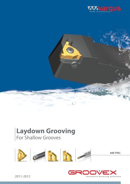
Laydown GroovingFor Shallow GroovesVARGUS Ltd. mrktg@vargus.com www.vargus.com221-01169METRIC <strong>EE</strong>0 8 / 2 0 1 1EDITION 01