

GROUND FAULT MONITOR RCMA476 - Bender
GROUND FAULT MONITOR RCMA476 - Bender
GROUND FAULT MONITOR RCMA476 - Bender

You also want an ePaper? Increase the reach of your titles
YUMPU automatically turns print PDFs into web optimized ePapers that Google loves.
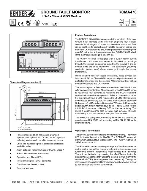
Quality SystemCertifiedISO 9001<strong>GROUND</strong> <strong>FAULT</strong> <strong>MONITOR</strong>UL943 - Class A GFCI ModuleVDE IEC<strong>RCMA476</strong>I∆n<strong>MONITOR</strong>Product DescriptionA1 A2 T/R 11 12 14<strong>RCMA476</strong>TESTRESETONS+ S-ALARMT/R21 22 24I∆n6 mAThe BENDER <strong>RCMA476</strong> series extends the capability of standardGround Fault Monitors to the detection of ground fault leakagecurrents in all stages of power conversation equipment fromsimple rectifiers to sophisticated variable frequency drives andbrushless DC motor controllers, with signal content extending frompure DC to the low kHz range (except the RCMA473-33A whichlimits the frequency range to 50...60Hz).The <strong>RCMA476</strong> series is designed with a built-in 18mm currenttransformer. All power conductors to be monitored must gothrough the current transformer including the neutral if line-toneutralloads are to be monitored. The equipment groundingconductor (ground wire) should never go through the currenttransformer.Dimension Diagram (mm/inch)45 (1.77")70 (2.76")44 (1.73")31 (1.22")5 (0.2")99 (3.9")91 (3.58")53 (2.09")65 (2.56")73 (2.87")When installed with our special contactors, these devices arelisted per UL943 as Class A GFCI for personnel protection and canprotect single-phase and three-phase AC systems, with or withoutneutral conductors and DC systems.The alarm setpoint is fixed at 6mA as required per UL943, ClassA for personnel protection. The response of the <strong>RCMA476</strong> seriesto hazardous fault currents, is related to the UL943 standard,which requires an alarm response to follow an inverse time curve.For example, at 6mA, UL943 requires the GFCI to interrupt within5594msec (5.6 seconds), at10mA it must interrupt within 2694msec(2.4 seconds), at 25mA it must interrupt at 726msec (0.73 seconds)and at 250mA it must interrupt at 25msec. The <strong>RCMA476</strong> followsthis UL943 time curve, unlike any GFCI on the market today. Thisallows a longer response time for lower fault currents, while stillmaintaining a fast reponse time at higher fault currents.The monitor is designed for mounting in control and distributionpanels using DIN 35/15 rail according to DIN EN 50 022 or forscrew mounting.■■■■■■■■ø 4,3 (0.17") forscrew mountingFor grounded and high-resistance grounded1-phase and 3-phase AC, DC and AC/DC systemsincluding systems with variable frequency drivesOffers the highest degree of personnel protectionavailable todayAlarm set-point value 6mA as per UL943, Class ABuilt-in 18mm current transformerOperation and Alarm LEDsTwo alarm outputs (SPDT contacts)Combined test / reset buttonTwo-year warrantyOperational InformationThe green LED indicates that the monitor is operating. The yellowLED indicates the unit is in ALARM. The <strong>RCMA476</strong> series willalarm when a ground fault exceeds 6mA. The <strong>RCMA476</strong> offers (2)SPDT alarm contacts.The <strong>RCMA476</strong> can be reset by pushing the buttonon the front of the unit for 1 second or by using the external resetfunction via the two T/R terminals (close for less than 1 second).The unit can be tested by pressing the button forgreater than 2 seconds or by using the external test function via thetwo terminals T/R (close for greater than 2 seconds). Testing canalso be done via an external test resistor which allows a test currentto flow through the current transformer.<strong>Bender</strong> Inc. - 700 Fox Chase, Coatesville, PA 19320 - Toll-free: (800) 356-4266 - Fax: (610) 383-7100
Technical Data <strong>RCMA476</strong> SERIESInsulationRated insulation voltageAC 250 VRated impulse withstand voltage/contamination grade4 kV/3Hi-pot test3 kVOperation classcontinuous operationSupply VoltageSupply voltage U SAC/DC 77...286VMax. power consumption4 VAAlarm Response ValueAlarm set-point value I ∆n1(<strong>RCMA476</strong> person. protec.) 6 mA- Frequency range (<strong>RCMA476</strong>-33) 0...700Hz- Frequency range (<strong>RCMA476</strong>-33A) 50...60HzResponse timeInverse Time CurveHysteresis25% of the response valueMeasuring CircuitCurrent transformer,- internal (18mm) <strong>RCMA476</strong>- external see RCMA473Alarm RelayType2 voltage-free SPDT contactsRated contact voltageAC 250 V/DC 300 VRated currentUC 5 ABreaking capacity:- AC 230 V and p.f. = 0.4 AC 2 A- DC 220 V and L/R = 0.04 s DC 0.2 AOperating modeN.D. modeAdjustment by factoryN.D. modeTesting StandardsEMI test:- Electrical disturbance test EN 50082-2- ESD IEC 801-2/EN 60801-2- EM field IEC 801-3- Burst IEC 801-4- Surge IEC 801-5Dielectric test:- Test voltage 2kV- Impulse voltage test IEC 255, Class III- Electrical disturbance test IEC 255Disturbance transmission EN 50081-1EmissionEN 55011 / CISPRIIShock resistanceIEC 41B(CO)38 class IBumping IEC 68-2-29Vibration amplitudeIEC TC41B class IEnvironmental ConditionsAmbient temperature, during operation -10°C ... +55°CStorage temperature range-40°C ... +70°CClimate class according to IEC 721 3K5, without condensationGeneral DataInternal CT opening (<strong>RCMA476</strong>)18 mmType of connectionscrew terminalsWire sizesolid14 AWGstranded16 AWGRapid mountingDIN #3 rail EN50022Screw mounting90.7 x 64.8 mm centeredProtection class acc. to DIN 40050- Internal components IP30- Terminals IP20Type of housingX470Weight approx.1 lbPLEASE NOTE: Check the label for correct supply voltage before applyingpower to the unit. The ground conductor must not be passed through thecurrent transformer unless the ground conductor is to be monitored by itself.Before starting the operation, it is recommended to carry out a functional testby applying a ground fault via a suitable resistance. Electrical equipmentshould only be installed by qualified personnel and in compliance withcurrent safety regulations.Ordering GuideModel Supply Setpoint FrequencyVoltage U SRange<strong>RCMA476</strong>-33 AC/DC 77-264V 6mA 0...700Hz<strong>RCMA476</strong>-33A AC/DC 77-264V 6mA 50...60Hz<strong>Bender</strong> Industrial Products - 700 Fox Chase, Coatesville, PA 19320 - Toll-free: 800-356-4266 - Fax: 610-383-7100
<strong>RCMA476</strong>Wiring DiagramDCL+L-L1L2L3NGND(A1 and A2 terminals)Supply Voltage AC/DC 77...264VAC(T/R terminals)external test and reset button (samefunction as built-in test/reset button)Fuse 6 AA1A2Power On LED(green)A1RCMA 476A2T/R11 12 146 mATESTRESETONALARMS+ S-T/R21 22 24alarm LED turns ON whenthe response value isreached (yellow)combined test and reset buttonshort-time pressing (2s) = Test1121(S+ and S- terminals) onlyused with BENDERINS465/466 Series.14 1224 22Alarm relay switches when theresponse value is reachedGround12/2005


