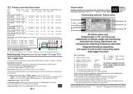
LiPoCard up to V6 - Schulze Elektronik GmbH
LiPoCard up to V6 - Schulze Elektronik GmbH
LiPoCard up to V6 - Schulze Elektronik GmbH

You also want an ePaper? Increase the reach of your titles
YUMPU automatically turns print PDFs into web optimized ePapers that Google loves.
1e<br />
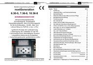
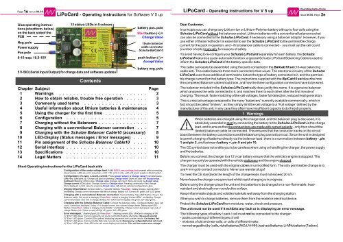
Page Issue 09.05 <strong>LiPoCard</strong> - Operating instructions for V 5 <strong>up</strong><br />
Glue operating instructions<br />
(shortform, below)<br />
on the back sideof the<br />
PCB<br />
Neg. pole<br />
Power s<strong>up</strong>ply<br />
Pos pole<br />
9-15 resp. 10,5-15V<br />
<strong>LiPoCard</strong> - Operating instructions for Software V 5 <strong>up</strong><br />
13 status-LEDs in 5 colours<br />
5 V-SIO (Serial Input/Output) for charge data and software <strong>up</strong>dates<br />
Contents<br />
battery pos. pole<br />
Start but<strong>to</strong>n (+) =<br />
Change Value<br />
10-pin balancer<br />
cable connec<strong>to</strong>r<br />
<strong>Schulze</strong> BalCab10<br />
push but<strong>to</strong>n (-) =<br />
Accept Value<br />
battery neg. pole<br />
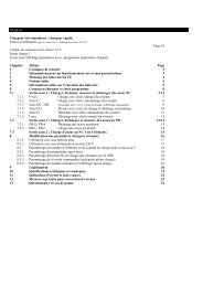
Chapter Subject Page<br />
1 Warnings . . . . . . . . . . . . . . . . . . . . . . . . . 2<br />
2 How <strong>to</strong> obtain reliable, trouble free operation . . . . . . 3<br />
3 Commonly used terms . . . . . . . . . . . . . . . . . . 3<br />
4 Useful information about lithium batteries & maintenance 4<br />
5 Using the charger for the first time . . . . . . . . . . . . 5<br />
6 Configuration . . . . . . . . . . . . . . . . . . . . . . . 5<br />
7 Charging without the Balancers . . . . . . . . . . . . . . 7<br />
8 Charging with a conventional Balancer connection . . . 7<br />
9 Charging with the <strong>Schulze</strong> Balancer Cable10 (accessory) 8<br />
10 LED-Display (Status messages / Error messages) . . . . 9<br />
11 Pin assignment of the <strong>Schulze</strong> Balancer Cable10 . . . . 10<br />
12 Serial interface . . . . . . . . . . . . . . . . . . . . . . . 10<br />
13 Specifications . . . . . . . . . . . . . . . . . . . . . . . 10<br />
14 Legal Matters . . . . . . . . . . . . . . . . . . . . . . . 11<br />
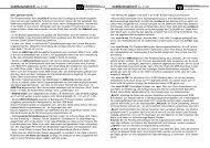
Short-Operating instructions for the <strong>LiPoCard</strong> back side<br />
Configuration of the under voltage level: Hold POR: Lower voltage limit pressed while connecting<br />
power source. LEDs go out in sequence. v-limit = 9V. Limit is only valid until power s<strong>up</strong>ply is disconnected.<br />
Configuration of c.type, c.count, current: Press Accept value(-) & Change value(+) simultaneously.<br />
LiPo resp. LiIo lights <strong>up</strong>. Change cell type by pressing Change value. S<strong>to</strong>re cell type with Accept value.<br />
CellCount=Balancer LED(s) glow. Change value changes cell count. S<strong>to</strong>re cell count by Accept value.<br />
Charge current LED(s) glow. Change current by Change value. Pressing continously = fast change.<br />
S<strong>to</strong>re displayed current value by pressing Accept value. All aboved selected configurations glow.<br />
Charging without Balancer: Connect battery - Type-LED* flashes. Press Start - battery charges, Current-LEDs**<br />
are flashing. Charge current decreases near end of charge. Battery full: Current off, green „full“-LED glows.<br />
Charging with a conventional Balancer connection: Connect battery, Type-LED* flashes. Plug in the<br />
Balancer cable, Cell count is displayed. Press Start - battery is charging, Current-LEDs** are flashing. Charge<br />
current decreases near end of charge. Battery full: Yellow current-LED(s) off, green „full“-LED glows.<br />
Charging with the <strong>Schulze</strong> Balancer Cable: Connect the balancer cable - Configured battery type, cell<br />
count, current are displayed. Using >1 A charge current: also connect charge leads. Battery type-LED*<br />
flashes. Press Start - battery is charging, Current-LEDs** are flashing. Charge current decreases near end of<br />
charge. Battery full: Yellow current-LED(s) off, green „full“-LED glows.<br />
Error messages: *) flashing type-LED: Press Start. **) flashing current-LEDs: <strong>LiPoCard</strong> is charging, all OK.<br />
1) "Error"-LED glows. Current (yellow) & cell count (red)-LEDs flashing alternately: Reversed polarity!<br />
2) "Error"-LED glows. Current-LEDs (yellow) displaying sequential from outside->inside: Car battery flat!<br />
3) "Error"-LED glows. Cell-count-LEDs flash betw. two cell counts: Discrepancy configurated/actual cell count.<br />
4) "Error"-LED glows. One LED in the cell count display (red) flashes: This cell has under-/over-voltage!<br />
Operating Instructions<br />
Issue 09.05, Page 2e<br />
Dear Cus<strong>to</strong>mer,<br />
In principle you can charge any Lithium-Ion or Lithium-Polymer battery with <strong>up</strong> <strong>to</strong> four cells using the<br />
<strong>Schulze</strong> <strong>LiPoCard</strong> without the balancer socket. Lithium batteries with a conventional balancer socket<br />
can also be connected <strong>to</strong> the <strong>Schulze</strong> <strong>LiPoCard</strong>, if necessary using a balancer adap<strong>to</strong>r. However, if you<br />
use either of these methods it is essential <strong>to</strong> set the <strong>Schulze</strong> <strong>LiPoCard</strong> <strong>to</strong> the permissible charge<br />
current for the pack in question, and - if no balancer cable is connected - you must set the cell count<br />
(number of cells) manually for reasons of safety.<br />
To avoid having <strong>to</strong> re-configure your <strong>Schulze</strong> <strong>LiPoCard</strong> separately for each battery, the <strong>Schulze</strong><br />
<strong>LiPoCard</strong> features a quasi-au<strong>to</strong>matic function: a special <strong>Schulze</strong> <strong>LiPoCard</strong> Balancing Cable is used <strong>to</strong><br />
inform the <strong>Schulze</strong> <strong>LiPoCard</strong> of the battery-specific data.<br />
The cable can easily be assembled using the parts contained in the BalCab10 set (10-way balancing<br />
cable set). This cable features three more connec<strong>to</strong>rs than usual. The electronic circuitry of the <strong>Schulze</strong><br />
<strong>LiPoCard</strong> uses these additional terminals <strong>to</strong> detect the type of battery connected <strong>to</strong> it, and the permissible<br />
charge current for that battery type. The instructions s<strong>up</strong>plied with the BalCab10 set describe how<br />
the completed Balancer cable should look, and how the three configuration connec<strong>to</strong>rs have <strong>to</strong> be wired.<br />
The balancer included in the <strong>Schulze</strong> <strong>LiPoCard</strong> really does justify this name. It is a genuine balancer<br />
which analyses the cells connected <strong>to</strong> it, and matches them <strong>to</strong> each other after the first minute of<br />
charging. The result: faster matching of the cell voltages, faster full detection, reduced heat generation.<br />
This is a real advantage compared <strong>to</strong> the many “balancers” currently available commercially, which in<br />
fact should be called “limiters”, as they simply limit the cell voltage <strong>to</strong> a “Full voltage” defined by the<br />
manufacturer of the unit; in any case they often have insufficient capacity <strong>to</strong> do the job properly.<br />
1 Warnings<br />
When batteries are charged using the charge lead, and the balancer plug is also used, it is<br />
absolutely essential <strong>to</strong> start by connecting the battery <strong>to</strong> the <strong>Schulze</strong> <strong>LiPoCard</strong> via the charge<br />
lead, and <strong>to</strong> ensure that the connections are made with correct polarity - only then should the<br />
(tested) balancer cable be connected. This ensures that the conduc<strong>to</strong>r tracks on the circuit<br />
board between the battery connections and the balancer plug cannot burn out. Since the unit is designed<br />
<strong>to</strong> permit charging of batteries directly via the balancer lead, there is a connection between battery -, pin<br />
1 and pin 2, and between battery +, pin 9 and pin 10.<br />
The CE symbol does not entitle you <strong>to</strong> be careless when using or handling the charger, the power s<strong>up</strong>ply<br />
and the batteries.<br />
Before you connect the charger <strong>to</strong> a 12 V car battery ensure that the vehicle's engine is s<strong>to</strong>pped. The<br />
charger may only be operated with the vehicle stationary and the engine s<strong>to</strong>pped.<br />
The charger must be used with the original cables in unmodified form. The only permissible change is <strong>to</strong><br />
use 4 mm gold-contact connec<strong>to</strong>rs. Never use wander plugs!<br />
To meet the CE standards the length of the charge leads must not exceed 20 cm.<br />
Never leave the charger uns<strong>up</strong>ervised whilst rapid-charging is in progress.<br />
Before using the charger place the unit and the batteries <strong>to</strong> be charged on a non-flammable, heatresistant<br />
and electrically non-conductive surface.<br />
Keep inflammable objects and volatile materials well away from the charging station.<br />
When you wish <strong>to</strong> charge batteries, remove them from the model or electrical device.<br />
Protect the <strong>Schulze</strong> <strong>LiPoCard</strong> from moisture, water, shock and pressure.<br />
The unit must not be used if it exhibits any fault or is displaying an error message.<br />
The following types of battery / pack / cell must not be connected <strong>to</strong> the charger:<br />
- packs consisting of different types of cell<br />
- mixtures of old and new cells, or cells of different make<br />
- non rechargeable (dry-)cells, nickel batteries (NiCd, Ni-MH), lead-acid batteries, Li-MNo batteries (Tadiran).
3e<br />
Page Issue 09.05 <strong>LiPoCard</strong> - Operating instructions for V 5 <strong>up</strong><br />
<strong>LiPoCard</strong> - Operating instructions for V 5 <strong>up</strong><br />
2 How <strong>to</strong> obtain reliable, trouble free operation<br />
It is essential <strong>to</strong> protect the charger from direct sunshine, dust, damp and rain. If the unit gets wet, dry it<br />
out thoroughly and have it checked and cleaned before re-use.<br />
The unit produces considerable heat in use. Allow excess heat <strong>to</strong> dissipate.<br />
Check the unit regularly for damage and/or poor contact between cab-les and connec<strong>to</strong>rs.<br />
Keep the charge cables as short as possible. Cables longer than 20 cm cannot be used if you wish <strong>to</strong><br />
conform <strong>to</strong> CE regulations. The internal battery wiring must also be as short as possible - especially <strong>to</strong><br />
protect the connected speed controllers against damage in use. Cable cross-section should be 2.5mm2 when you charge with more than 2 amps charge current.<br />
The charge cable should be fitted with high-quality gold-contact connec<strong>to</strong>rs at both ends.<br />
Twist charge leads <strong>to</strong>gether <strong>to</strong> minimise interference radiation.<br />
It is not permissible <strong>to</strong> operate the <strong>Schulze</strong> <strong>LiPoCard</strong> while the power source (car battery) is being<br />
charged by a conventional battery charger. It is generally possible <strong>to</strong> operate the unit from a stabilised<br />
mains PSU (11 - 13.8 V), provided that it has a current capacity of at least 7 A, but it is still essential that<br />
you check the compatibility of the system.<br />
Where individual cells are <strong>to</strong> be charged simultaneously, they must be soldered <strong>to</strong>gether <strong>to</strong> ensure that<br />
the <strong>Schulze</strong> <strong>LiPoCard</strong> operates correctly.<br />
The <strong>Schulze</strong> <strong>LiPoCard</strong> only sets the charge current calculated for a particular pack if that current does<br />
not cause any of the charger's parameters <strong>to</strong> be exceeded.<br />
The information and charging currents stated by the battery manufacturer must be observed at all times.<br />
3 Commonly used terms<br />
Final charge voltage: the voltage at which the battery’s charge limit (or capacity limit) is reached. When<br />
the <strong>Schulze</strong> <strong>LiPoCard</strong> is in use, the current is reduced <strong>to</strong> less than 8% of the configured value at this<br />
point. The charger then switches off, and displays the “battery full” indica<strong>to</strong>r.<br />
Final discharge voltage: the voltage at which the battery's discharge limit is reached. The chemical<br />
composition of the batteries determines the level of this voltage. Below this voltage the battery enters the<br />
deep discharge zone. Deep discharged cells can cause permanent damage<br />
Power-On (- reset): the status of the <strong>Schulze</strong> <strong>LiPoCard</strong> after it has been connected <strong>to</strong> the car<br />
battery.<br />
Ready display: the charger is ready (batteries disconnected) <strong>to</strong> operate at the currently selected<br />
configuration. When in this state the unit displays the set configuration by means of continuously glowing<br />
LEDs.<br />
Lademenge, Kapazität: siehe C und Ah bzw. mAh.<br />
C: Coulomb or capacity: Unit of measurement relating <strong>to</strong> the quantity of charged energy. In conjunction<br />
with charge current data this unit is used <strong>to</strong> determine the recommended / prescribed charge current<br />
of a battery of a given capacity. Example: if the charge current of a 1100 mAh battery is 2,2 A, we refer <strong>to</strong><br />
this as a charge of 2 C.<br />
A, mA: unit of measurement relating <strong>to</strong> charge or dis-charge current. 1000 mA = 1 A (A=Ampere,<br />
mA=Milliampere). Do not mix <strong>up</strong> with:<br />
Ah, mAh: unit of measurement for the capacity of a battery (Amperes x time unit; h = hour). If a pack is<br />
charged for one hour at a current of 2 A, it has been fed 2 Ah of energy. It receives the same quantity of<br />
charge (2 Ah) if it is charged for 4 hours at 0.5 A, or 15 minutes (=1/4 h) at 8 A.<br />
Operating Instructions<br />
Issue 09.05, Page 4e<br />
4 Useful information about Lithium batteries (Li-Io & Li-Po) and their maintenance<br />
Li-Io (Lithium-Ion) cells are housed in a strong metal can, usually of cylindrical shape. Their designation is derived<br />
from the <strong>to</strong>xic ion-conducting fluid electrolyte. The rigid metal container is required <strong>to</strong> ensure that the electrodes<br />
are pressed firmly enough against the separa<strong>to</strong>r. Li-Io cells of cylindrical and prismatic format have been in<br />
existence for many years; they were originally stated <strong>to</strong> have a nominal voltage of 3.6 V, with a maximum charge<br />
voltage of 4.1 V.<br />
Some distribution companies now state a maximum charge voltage of 4.2 V for the Li-Io cells which have been<br />
developed more recently. In our opinion we should always rely <strong>up</strong>on the voltages stated by the cell manufacturer,<br />
i.e. the company which designed the cell.<br />
As a basic rule the Li-Io cells stated <strong>to</strong> be safe at 4.2 V can also be charged <strong>to</strong> 4.1 V. If you do this, you can<br />
usually - depending on the cell design - expect a slight extension of useful battery life, combined with a reduction<br />
in usable capacity.<br />
Li-Po (Lithium-Polymer) cells derive their designation from the polymer foil which was originally used as the<br />
electrolyte. This “solid” electrolyte was only capable of s<strong>up</strong>plying current at temperatures of around 60ºC or<br />
higher; later the electrolyte was enriched with various s<strong>up</strong>plementary materials <strong>to</strong> provide improved conductivity.<br />
The characteristics of these new cells made it possible <strong>to</strong> house them in a lightweight foil pack (“flat-pack”); these<br />
cells now provide a very high performance even at room temperature, although they still have slightly more <strong>to</strong> offer<br />
at 60ºC.<br />
The uniform nominal voltage of these cells is stated as 3.7 V, the maximum charge voltage as 4.2 V.<br />
As the differences between the types is generally not made clear in the modelling world, we provide the following<br />
definitions:<br />
Nominal voltage LiIo: 3.6 V / cell (SAFT)<br />
Nominal voltage LiIo/LiPo: 3.7 V / cell (SANYO, KOKAM)<br />
Max. charge voltage LiIo: 4.1 V +-40mV / cell (SAFT)<br />
LiPo: 4.2 V +-50mV / cell (MoliCel)<br />
absolute limit 4.3 V / cell<br />
Min. discharge voltage LiIo: 2.5 V / cell (MoliCel), 2.7V/Z.(SANYO)<br />
LiPo: 3.0 V / cell (KOKAM)<br />
absolute limitt 2.3 V / cell<br />
Number of cells <strong>to</strong> be selected on the <strong>Schulze</strong> <strong>LiPoCard</strong>:<br />
Nominal voltage of LiPo-pack div.by nominal cell-voltage = cell count.<br />
--> 11,1 V LiPo-pack divided by 3.7 V => select 3 cells!<br />
If you would select more, the pack would explode during charging - if the cell count moni<strong>to</strong>ring circuit of<br />
the <strong>Schulze</strong> <strong>LiPoCard</strong> would fail.<br />
Example: The ThunderPower TP8200 3s4p pack consists of 12 cells.<br />
4 of 2050mAh are connected parallel (4p) -> 4 * 2,05 Ah = 8200mAh.<br />
3 of the paralleled cells are connected in series (3s)-> 3*3,7V= 11,1 V.<br />
Selecting the fitting cell type:<br />
Select that battery type (Li-Ion bzw. Li-Poly), which characteristics match best with the data sheet of<br />
the battery manufacturer.<br />
Selecting the fast charge current - if the manufacturer does not specify other values:<br />
Charge current = 1 C (SANYO / KOKAM) or less (0,7 C PANASONIC) (C = nominal battery capacity).<br />
Maximum continous discharge current when used as a drive battery:<br />
Depending on the cell type: 1 ... 20 C continous current..<br />
Long time s<strong>to</strong>rage:<br />
Empty, i.e. discharged <strong>to</strong> the discharge voltage cut off level (see maintenance), at low temperature (-<br />
20°C bis +10°C).<br />
Maintenance: Discharge <strong>up</strong> <strong>to</strong> 1 C down <strong>to</strong> the above listed discharge voltages. Always s<strong>to</strong>re these<br />
cells in the discharged state. If s<strong>to</strong>red fully charged over a longer period, the result can be a permanent<br />
reduction in capacity.<br />
When s<strong>to</strong>red at +40°C or more charge them additionally a little bit every two months.
5e<br />
Page Issue 09.05 <strong>LiPoCard</strong> - Operating instructions for V 5 <strong>up</strong><br />
<strong>LiPoCard</strong> - Operating instructions for V 5 <strong>up</strong><br />
5 Using the charger for the first time<br />
5.1 5.2<br />
5.3<br />
Take the <strong>Schulze</strong> <strong>LiPoCard</strong> out of the packaging and solder your choice of connec<strong>to</strong>rs <strong>to</strong> the 2.5 mm²<br />
charger cables: -5.1- crocodile clips or -5.2- 3.5 mm / 4 mm / MPX high current gold-contact plugs.<br />
-5.2- Never use segmented or metal sheet connec<strong>to</strong>rs, as they represent a high risk of intermittent contact.<br />
Ensure that the power s<strong>up</strong>ply you intend <strong>to</strong> use (e.g. 13.8 V mains PSU) delivers stable power and has no<br />
reciprocal side-effects. A 12 V car battery is a suitable alternative. Flight / drive batteries of 1.5 Ah capacity or<br />
larger can also be used (3-cell Lithium batteries (3s…), 10-11 cell nickel (Ni-Cd, NiMH) battery).<br />
First switch on the mains PSU. Connect the <strong>Schulze</strong> <strong>LiPoCard</strong> quickly and confidently <strong>to</strong> the power s<strong>up</strong>ply. If<br />
you are using a flight / drive battery as power source, you must remember <strong>to</strong> reduce the low voltage limit.<br />
-5.4- Mains PSU / car battery,<br />
11-15 V: after the LED test (1<br />
sec.), the unit displays the<br />
configuration which is s<strong>to</strong>red in<br />
the <strong>Schulze</strong> <strong>LiPoCard</strong> (-5.6-).<br />
5.4 5.51 5.52 5.53<br />
5.6<br />
-5.5- Other battery, 9-15V: hold the POR: Lower voltage limit but<strong>to</strong>n (-)<br />
pressed in while you connect the power source, and hold it pressed in until the<br />
end of the LED test. The LED test ends when the LEDs go out in sequence<br />
from red <strong>to</strong> yellow. The unit then displays the configuration which is s<strong>to</strong>red in<br />
the <strong>Schulze</strong> <strong>LiPoCard</strong> (-5.6-). Limit is valid until power s<strong>up</strong>ply disconnected.<br />
6 Configuration (setting the operating parameters)<br />
If you connect a battery using a <strong>Schulze</strong> BalancerCable (special balancer lead for the <strong>Schulze</strong><br />
<strong>LiPoCard</strong>), you could skip this section (Chapter 6). The <strong>Schulze</strong> BalancerCable passes on the<br />
essential configuration information <strong>to</strong> the <strong>Schulze</strong> <strong>LiPoCard</strong>, so that the charger does not need <strong>to</strong> be reconfigured<br />
in order <strong>to</strong> charge this particular battery. However, we still recommend that you s<strong>to</strong>re a<br />
configuration for those battery packs which are not fitted permanently with a <strong>Schulze</strong> BalancerCable.<br />
These are generally the smallest and lightest packs used for indoor flying, where every gramme of saved<br />
weight counts.<br />
It is only possible <strong>to</strong> enter the configuration mode when the flight battery is disconnected. The configuration<br />
process starts when you press Accept value (-) and Change value (+) simultaneously. The “Config.”<br />
LED (green, “Full”) lights <strong>up</strong> at the same time as one of the two battery type LEDs.<br />
Selecting the battery type is the first of three steps which must be carried out in the correct sequence.<br />
If you arrive at the configuration menu by mistake, you can close it without changing the configuration by<br />
pressing the Accept value but<strong>to</strong>n repeatedly (at least three times).<br />
6.1<br />
-6.1- Enter the configuration mode<br />
of the <strong>Schulze</strong> <strong>LiPoCard</strong>: press<br />
Accept value (-) and Change<br />
value (+) simultaneously. The<br />
card is now ready for entering the<br />
battery type.<br />
-6.4- One <strong>to</strong> four LEDs now glow.<br />
Every time you press Change value<br />
the cell count increments by<br />
one from 1 <strong>to</strong> 4, in bar graph form,<br />
i.e. the more LEDs that light <strong>up</strong>, the<br />
higher the cell count.<br />
-6.7- If the LEDs display 100 + 250 + 500<br />
= 850 mA, pressing Change value once<br />
increases the charge current <strong>to</strong> 1000 mA<br />
(only one (yellow) LED glows). Pressing<br />
the pushbut<strong>to</strong>n (+) continously leads <strong>to</strong> a<br />
fast change.<br />
6.21<br />
6.22<br />
-6.2- Li-Poly (blue) or Li-Ion (orange)<br />
glows. Every time you press<br />
Change value the cell type changes,<br />
i.e. the blue and orange LEDs light <strong>up</strong><br />
alternately.<br />
-6.5- Press Accept value <strong>to</strong> s<strong>to</strong>re<br />
the indicated cell count from 6.4<br />
in the charger’s memory. The<br />
<strong>Schulze</strong> <strong>LiPoCard</strong> now waits<br />
for you <strong>to</strong> enter the maximum<br />
charge current (one or more yellow<br />
LEDs light <strong>up</strong>).<br />
Operating Instructions<br />
Issue 09.05, Page 6e<br />
6.41 6.42 6.43<br />
6.5 6.6<br />
6.71 6.72<br />
6.8<br />
6.3<br />
-6.3- Press Accept value <strong>to</strong> s<strong>to</strong>re<br />
the indicated cell type from 6.2 in<br />
the charger’s memory. The<br />
<strong>Schulze</strong> <strong>LiPoCard</strong> now waits for<br />
you <strong>to</strong> enter the cell count (one or<br />
more red LEDs light <strong>up</strong>).<br />
-6.6- The charge current is displayed<br />
in digital form: each LED<br />
indicates a particular current value.<br />
The <strong>to</strong>tal charge current is found<br />
by adding <strong>to</strong>gether all the indicated<br />
current values. Example: 1000<br />
+ 100 = 1100; 500 + 250 = 750.<br />
-6.8- Pressing Accept value s<strong>to</strong>res the indicated charge<br />
current (from 6.7) in the charger’s memory. This completes the<br />
configuration process for the <strong>Schulze</strong> <strong>LiPoCard</strong>, and the unit<br />
displays the overall configuration. The charger is now ready <strong>to</strong><br />
use, and waits for you <strong>to</strong> connect the battery you wish <strong>to</strong> charge,<br />
or the <strong>Schulze</strong> BalancerCable.
7e<br />
Page Issue 09.05 <strong>LiPoCard</strong> - Operating instructions for V 5 <strong>up</strong><br />
<strong>LiPoCard</strong> - Operating instructions for V 5 <strong>up</strong><br />
7 Charging without the Balancers<br />
7.11 7.12 7.2 7.31 7.32<br />
-7.1- Connect the battery <strong>to</strong> the 4 mm<br />
sockets, taking care <strong>to</strong> maintain<br />
correct polarity. Check the cell count<br />
and battery type. If polarity is correct<br />
and the charger does not detect an<br />
incorrect cell count, the battery type<br />
LED flashes (= “Ready”).<br />
-7.2- Press the Start (+)<br />
but<strong>to</strong>n <strong>to</strong> initiate the charge<br />
process. The battery type LED<br />
now lights <strong>up</strong> continuously,<br />
and the yellow current LED(s)<br />
are flashing (= “Charging”).<br />
8 Charging with a conventional Balancer connection<br />
-7.3- The current fed <strong>to</strong> the<br />
battery declines <strong>to</strong>wards the end<br />
of the charge process. When the<br />
battery is full, the charge current<br />
is switched off (LEDs out) and<br />
the “Full” LED (green) now<br />
glows constantly.<br />
8.11 8.12 8.21<br />
8.22<br />
-8.1- Connect the battery via the charging cable <strong>to</strong><br />
the two outside 4 mm banana sockets, taking care <strong>to</strong><br />
maintain correct polarity.<br />
If everything is in order, the battery type LED flashes<br />
“Ready” for the charge process (even if the cell<br />
terminals are not connected). If the pack is<br />
connected with reversed polarity, the Error LED<br />
glows; it also lights <strong>up</strong> if the cell count is incorrect<br />
(see Chapter 10: Display: Error messages).<br />
If a reverse-polarity connection is present, this<br />
MUST be corrected before you connect the cell<br />
count detect socket. Neglecting <strong>to</strong> do this could<br />
result in damage <strong>to</strong> the <strong>Schulze</strong> <strong>LiPoCard</strong>, with the<br />
result that the Balancer plug can no longer be used.<br />
In contrast, if the cell count is false, the error is<br />
corrected immediately when the Balancer plug is<br />
connected.<br />
-8.2- Plug in the Balancer cable.<br />
The pack’s cell count now would displayed<br />
correctly if it had been configurated unsuitable in<br />
the <strong>Schulze</strong> <strong>LiPoCard</strong>. The battery type LED<br />
flashes <strong>to</strong> indicate “Ready”. Check the battery type<br />
configuration: this parameter cannot be detected<br />
au<strong>to</strong>matically by the <strong>Schulze</strong> <strong>LiPoCard</strong>.<br />
Note: Before you connect one of the non-standard<br />
cell count detect sockets <strong>to</strong> the odd pin row (start<br />
with pin 1, 3, 5, 7, 9) of the <strong>Schulze</strong> <strong>LiPoCard</strong>,<br />
please ensure that it fits physically, i.e. in terms of<br />
dimensions, and that the pin sequence is correct<br />
(see Chapter 11), otherwise you might damage the<br />
Balancer plug. If the connec<strong>to</strong>rs are not compatible,<br />
an adap<strong>to</strong>r must be used; even better: switch <strong>to</strong> the<br />
<strong>Schulze</strong> BalancerCable system, so that you can<br />
exploit its advantages and foolproof characteristics.<br />
Please continue now reading at Chapters 9.3 and 9.4. The sequence is identical <strong>to</strong> sections 8.3 and 8.4.<br />
9 Charging with the <strong>Schulze</strong> BalancerCable10 (accessory)<br />
Operating Instructions<br />
Issue 09.05, Page 8e<br />
9.11 9.12<br />
9.21 9.22<br />
-9.11- Configurated <strong>to</strong> LiPo, 2s(1p), 350 mA(h). connec<strong>to</strong>r is plugged in (9.2).<br />
-9.12- If you have set a charge current above 1 Since the contacts of the Balancer plug are connected<br />
Ampere connect the battery <strong>to</strong> the two outer 4 mm directly <strong>to</strong> the banana sockets of the <strong>Schulze</strong> Bal-<br />
banana sockets on the <strong>Schulze</strong> <strong>LiPoCard</strong>. MainancerCable, the battery can be charged directly via<br />
tain correct polarity! For charge currents <strong>up</strong> <strong>to</strong> 1 A the Balancer connec<strong>to</strong>r pro-vided that the charge<br />
this charge lead does not need <strong>to</strong> be used (go <strong>to</strong> current is no higher than 1 A.<br />
section 9.2).<br />
However, the connection between the Balancer plug<br />
If everything is in order, the battery type LED flashes. contacts and the banana sockets is also the reason<br />
If the pack is connected with reversed polarity, the why the <strong>Schulze</strong> <strong>LiPoCard</strong> is susceptible <strong>to</strong> damage<br />
Error LED glows; it also lights <strong>up</strong> if the cell count is if the polarity of the Balancer plug is not the same as<br />
incorrect (Error: see pict.9.12; <strong>LiPoCard</strong> is configu- the polarity of the charge lead.<br />
rated <strong>to</strong> 2 cells and has detected three cells. See also<br />
Chapter 10: Display: Error messages).<br />
-9.2- Connect the <strong>Schulze</strong> BalancerCable <strong>to</strong> the<br />
Balancer socket. The <strong>Schulze</strong> <strong>LiPoCard</strong> now dis-<br />
If a reverse-polarity connection is present, this MUST plays the battery type, the cell count and the maximum<br />
be corrected before you plug in the <strong>Schulze</strong> Bal- charge current as configured by the cable (LiPo, 3<br />
ancerCable.<br />
cells, Max.current). The “LoPo” LED flashes <strong>to</strong> indi-<br />
In contrast, if the cell count is false, the error is<br />
corrected immediately when the cell count detect<br />
cate that the charger is “Ready” (9.21/9.22).<br />
-8.3/9.3- Press the Start (+) but<strong>to</strong>n <strong>to</strong> initiate the<br />
charge process. The battery type LED now lights<br />
<strong>up</strong> continuously, and the charge current LED(s)<br />
are flashing <strong>to</strong> show that the charger is working.<br />
Hint: The LED(s) are switched off for a short<br />
period every second.<br />
9.3 9.41 9.42<br />
-8.4/9.4- The current fed <strong>to</strong> the battery declines<br />
<strong>to</strong>wards the end of the charge process. Picture 9.41<br />
shows that cell no. 1 is just in balancing process (LED<br />
1 out). When the battery is full, the charge current is<br />
switched off and the “Full” LED (green) glows constantly(9.42).<br />
The yellow LEDs then show by short<br />
blinking the capacity charged in (Example: A display<br />
of 1500 mA means 1500 mAh charged in).
9e<br />
Page Issue 09.05 <strong>LiPoCard</strong> - Operating instructions for V 5 <strong>up</strong><br />
-10.11- „Ready“<br />
Li-Poly (blue) or<br />
Li-Io (orange)<br />
flashes when the<br />
battery is connected.<br />
Press Start.<br />
<strong>LiPoCard</strong> - Operating instructions for V 5 <strong>up</strong><br />
10.1 LED display - Status messages<br />
-10.12- „Charging“<br />
Current LEDs (yellow)<br />
are flashing.<br />
<strong>LiPoCard</strong> charges.<br />
No intervention is<br />
required.<br />
10.2 LED display - Balancer function<br />
-10.21- Four cells are being charged. Cells 2 and 4 are being balanced -10.22-<br />
The Balancer LEDs normally indicate the cell count. When the Balancer is operating,<br />
the LED for the cell(s) currently being balanced goes out, <strong>to</strong> indicate that the cell<br />
concerned is “no longer available” for charging. A reduced charge current flows in<strong>to</strong><br />
this cell compared <strong>to</strong> the other cells, i.e. the Balancer diverts part of the charge<br />
current past this one cell (or several cells).<br />
10.31 10.32 10.33<br />
10.3 LED display - Charge current display<br />
The unit indicates the charge current in digital form: each LED<br />
displays a particular current value. The actual charge current is<br />
found by adding <strong>to</strong>gether all the indicated current values.<br />
-10.31- 500 + 250 = 750 mA: 740 mAh battery 0 … 80% full<br />
-10.32- 250 + 100 = 350 mA: 740 mAh battery more than 80% full<br />
-10.33- 100 + 100 mA: battery almost 100% full.<br />
-10.13 (!)- “Full” display = current switched off; see above.<br />
10.4 LED display - Error messages (Red error LED glows)<br />
-10.41- Reversed polarity<br />
Current LED (yellow) and cell count<br />
LED (red) flash alternately.<br />
Re-connect charge lead / Balancer<br />
plug the other way round!<br />
-10.44- Discrepancy between configured<br />
and actual cell counts. Cell count<br />
LEDs (red) flash, alternating between two<br />
cell counts. The error display disappears if<br />
a Balancer plug is connected. Otherwise:<br />
re-configure the cell count on the Card.<br />
-10.42- (Car) battery flat<br />
Current LEDs (yellow) light <strong>up</strong> in a<br />
sequential display from outside <strong>to</strong><br />
inside. Charge power s<strong>up</strong>ply<br />
battery (e.g. car battery).<br />
-10.45- Balancer wiring incorrect.<br />
All four cell count LEDs<br />
(red) flash <strong>to</strong>gether when the<br />
Balancer plug is connected.<br />
Check and correct the Balancer<br />
cable wiring.<br />
-10.13- „Full“<br />
“Full” LED (green)<br />
glows continuously.<br />
The yellow current<br />
LEDs are flashing<br />
the charged amount.<br />
10.41<br />
-10.47- Current <strong>to</strong>o high<br />
for the balancer cable.<br />
Use additional charge leads.<br />
-10.43- One cell outside permissible<br />
voltage range (<strong>to</strong>o low / <strong>to</strong>o<br />
high). One of the cell count LEDs<br />
(red) flashes. Bring the corresponding<br />
cell in<strong>to</strong> the permissible voltage<br />
range (2.5 … 4.2 V), or replace<br />
it if the cell is defective.<br />
-10.46- Current resistance not acceptable.<br />
All five current LEDs (yellow)<br />
flash when the Balancer plug is<br />
connected. Current resis<strong>to</strong>r defective;<br />
replace resis<strong>to</strong>r or pot.<br />
Operating Instructions<br />
Issue 09.05, Page10e<br />
11 Pin assignment of the <strong>Schulze</strong> BalancerCable10 plug/socket<br />
- 11- Table: Pin assignment 4 mm charge connec<strong>to</strong>r (female):<br />
<strong>LiPoCard</strong> Balancer plug 11<br />
+ battery (‘+’ of last cell: 1,2,3 or 4)<br />
Cable colour Assignment Pin Pin Assignment Cable colour<br />
brown battery + 10 9 ‘+’ batt. (‘+’ last cell: 1,2,3 or 4) red<br />
orange cell type 8 7 ‘+’ cell 3 (no connect at 2s pack) yellow<br />
green charge curr.(2) 6 5 ‘+’ cell 2 (no connect at 1s pack) blue<br />
lilac charge curr.(1) 4 3 ‘+’ cell 1 grey<br />
white battery - 2 1 ‘-’ cell 1 (battery -) black<br />
Note: pins 1 (black) and 2 (white)<br />
This makes it possible <strong>to</strong> charge small<br />
are always connected <strong>to</strong> the nega-<br />
batteries at low charge currents (max. 1<br />
tive charge lead terminal;<br />
A) using the <strong>Schulze</strong> Balancer Cable<br />
pin 9 and 10 is connected <strong>to</strong> the<br />
directly, i.e. without using a charge lead.<br />
positive terminal of the charge lead.<br />
- battery (‘-’ cell 1)<br />
Cell type detect: if the battery is a Li-Ion type, pin 8 (orange) must be connected <strong>to</strong> pin 4 (lilac); if it is a<br />
Li-Poly type, pin 8 (orange) must be connected <strong>to</strong> pin 6 (green). Prepare the ends of the ribbon cable<br />
wires as shown in Figs. 6 - 17.<br />
Charge current detect: the charge current for the battery pack is determined by a resis<strong>to</strong>r between pin<br />
4 (lilac) and pin 6 (green). The value of the resis<strong>to</strong>r is 1 Ohm per milli-Amp (mA) of charge current, i.e.<br />
360 mA = 360 Ohm; 1250 mA = 1250 Ohm, 3200 mA = 3.2 kOhm. Any value above 3.9 kOhm is<br />
possible (e.g. for a 6000mAh pack = about 6 kOhm); the LiPo Card then charges at the maximum<br />
possible current of 3850 mA. Permissible resis<strong>to</strong>r values are from 25 Ohm <strong>to</strong> 15 kOhm.<br />
12 Serial interface<br />
The <strong>Schulze</strong> <strong>LiPoCard</strong> features a TTL-level serial interface, which can be connected <strong>to</strong> the RS232 port<br />
of a PC using the <strong>Schulze</strong> prog-adapt-uni cable.<br />
Using this cable, the <strong>Schulze</strong> <strong>LiPoCard</strong> transfers <strong>Schulze</strong> winsoft-compatible data <strong>to</strong> the PC, where<br />
the charge voltage curve can be displayed in graphic form: the data consists of charge time, charge<br />
current, individual cell voltages (only if a Balancer is connected) and <strong>to</strong>tal battery voltage. If the balancer<br />
vcable is connected select „4 Cells Voltage“ <strong>to</strong> show the voltage of the single cells.<br />
When the charger detects “Battery full”, it also transfers the data for charged-in energy and discharged<br />
energy from the Balancer <strong>to</strong> the interface. This data can be analysed <strong>to</strong> glean valuable information about<br />
the condition of your battery packs.<br />
Software-Updates can also be done by yourself via this interface.<br />
13 Specifications<br />
Dimensions approx. 96*53*12 mm<br />
Weight approx. 52 g<br />
Cell count range 1 - 4 Li-Poly, Li-Ion<br />
Converter efficiency 80 - 96 %<br />
Max. charge power 65 W<br />
Charge current range 25 - 3850 mA 12 V power s<strong>up</strong>ply voltage and 16,8 V charge voltage<br />
Balancer socket 10-pin with current and battery type coding<br />
Power s<strong>up</strong>ply voltage 10.5 - 15 V DC<br />
Power s<strong>up</strong>ply, reduced 9 - 15 V DC<br />
Max. power s<strong>up</strong>ply current 7 A<br />
Power s<strong>up</strong>ply types 12 V - 13.8 V mains PSU, 12 V lead-acid battery,<br />
3-cell Lithium battery, 10 - 11 cell Nickel (Ni-Cd, NiMH) battery<br />
Operational mode display via 13 LEDs<br />
Operation via 2 push-but<strong>to</strong>ns<br />
Miscellaneous Serial interface, heat-shrink sleeve “case”.
11e<br />
Page Issue 09.05 <strong>LiPoCard</strong> - Operating instructions for V 5 <strong>up</strong><br />
<strong>LiPoCard</strong> - Operating instructions for V 5 <strong>up</strong><br />
14 Legal matters<br />
14.1 Warranty<br />
All <strong>Schulze</strong> <strong>LiPoCard</strong> chargers are carefully checked and tested before dispatch.<br />
If you have a complaint, send the unit back <strong>to</strong> us with a clear description of the fault.<br />
A message such as "doesn't work properly" or "software error" doesn't help us much!<br />
Before you send your <strong>Schulze</strong> <strong>LiPoCard</strong> back <strong>to</strong> us, please test the unit carefully, as it costs us money<br />
<strong>to</strong> test a charger, and if it turns out <strong>to</strong> be in working order we have <strong>to</strong> recover those costs from you. In<br />
this case it makes no difference whether the fully functional charger is returned within the warranty<br />
period or not. Approved warranty claims are processed in accordance with our currently valid General<br />
Conditions of Business, which are printed in our catalogue resp. on our homepage.<br />
One further note: if a problem arises with any schulze product, send it directly <strong>to</strong> us without interfering<br />
with it in any way.<br />
This ensures that we can repair the unit quickly, pick <strong>up</strong> warranty faults without any dispute, and keep<br />
costs <strong>to</strong> a minimum.<br />
You can also be sure that we will fit genuine replacement parts which will work properly in your unit.<br />
Unfortunately we have had bad experience with third-party Service Centres which claim technical<br />
competence. Note also that any out-side interference with our products invalidates the warranty (e.g. the<br />
original pole clamps omitted or replaced). Incompetent attempts at repair can cause further damage. We<br />
often find it impossible <strong>to</strong> estimate the repair cost of devices in such condition, and in certain circumstances<br />
we are then obliged <strong>to</strong> decline <strong>to</strong> repair it al<strong>to</strong>gether.<br />
14.2 Limited liability / compensation<br />
We at <strong>Schulze</strong> <strong>Elektronik</strong> <strong>GmbH</strong> are unable <strong>to</strong> moni<strong>to</strong>r the observance of our assembly and operation<br />
instructions, our prescribed conditions and methods for installation, connection, usage and maintenance<br />
of our battery chargers. For this reason we cannot accept liability for loss, damage or costs which arise<br />
through the inappropriate use of our products, or are connected in any way with such use.<br />
Within the normal legal limits, our obligation <strong>to</strong> provide compensation, for whatever legal reason, is<br />
limited <strong>to</strong> the invoice value of that quan-tity of product immediately involved in the event which caused the<br />
damage. This does not apply if we are obliged <strong>to</strong> accept unlimited liability in accordance with manda<strong>to</strong>ry<br />
law due <strong>to</strong> our deliberate or serious negligence.<br />
14.3 CE approval<br />
All <strong>Schulze</strong> <strong>LiPoCard</strong> units built after January 1996 satisfy all relevant and manda<strong>to</strong>ry EC directives:<br />
these are the EMF directives<br />
- 89/336/EWG, 91/263/EWG und 92/31/EWG.<br />
The product meets the following basic technical standards:<br />
Interference radiation: EN 50 081-1:1992, Interference susceptibility: EN 50 082-1:1992 and/or EN<br />
50 082-2:1995.<br />
You are the owner of a product whose design and construction fulfil the safety aims of the EC for the<br />
safe operation of devices.<br />
The procedure also includes a test of interfer-ence susceptibility, i.e. the extent <strong>to</strong> which the charger is<br />
vulnerable <strong>to</strong> interference from other devices. The test involves subjecting the charger <strong>to</strong> RF signals<br />
similar <strong>to</strong> those produced by an RC transmitter or a radio telephone.<br />
Operating Instructions<br />
Issue 09.05, Page12e<br />
schulze elektronik gmbh • prenzlauer weg 6 • 64331 weiterstadt • phone: +49-6150-1306-5 • fax: 1306-99<br />
www.schulze-elektronik-gmbh.com germany<br />
hotline@schulze-elektronik-gmbh.com