mcf 31/mcf 43: multi purpose speed controllers - Schulze Elektronik ...
mcf 31/mcf 43: multi purpose speed controllers - Schulze Elektronik ...
mcf 31/mcf 43: multi purpose speed controllers - Schulze Elektronik ...

You also want an ePaper? Increase the reach of your titles
YUMPU automatically turns print PDFs into web optimized ePapers that Google loves.
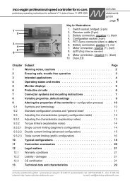
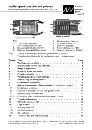
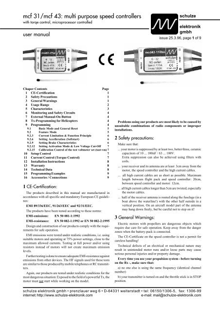
<strong>mcf</strong> <strong>31</strong>/<strong>mcf</strong> <strong>43</strong>: <strong>multi</strong> <strong>purpose</strong> <strong>speed</strong> <strong>controllers</strong><br />
with torqe control, microprocessor controlled<br />
user manual<br />
Chaper Contents Page<br />
1 CE-Certification 1<br />
2 Safety Precautions 1<br />
3 General Warnings 1<br />
4 Usage Range 2<br />
5 Characteristics 3<br />
6 Monitoring and Safety Circuits 4<br />
7 External Manual-On Button 4<br />
8 Tx-Programming for Helicopters 4<br />
9 Programming 4<br />
9.1 Basic Mode and General Reset 5<br />
9.2 Feature Mode 5<br />
9.2.3 Current Limitation & Function Principle 6<br />
9.2.6 Setting Accelleration (Softstart) 6<br />
9.2.9 Setting Brake Characteristics 6<br />
9.2.12 Setting Activation Mode & Low Voltage Cut-Off 7<br />
9.2.15 Calibration Control of the test voltmeter set (tast-vm) 7<br />
10 Setup Control 7<br />
11 Current Control (Torque Control) 7<br />
12 Installation Instructions 8<br />
13 Warranty 8<br />
14 Technical Data 8<br />
15 Programming Examples 9<br />
16 Accessories / Connections 9<br />
1 CE-Certification:<br />
The products described in this manual are manufactured in<br />
accordance with all specific and mandatory European CE guidelines:<br />
EMI 89/336/EEC, 91/263/EEC and 92/<strong>31</strong>/EEC.<br />
The products have been tested according to these norms:<br />
EMI-emissions: EN 50 081-1:1992<br />
EMI-resistance: EN 50 082-1:1992 or EN 50 082-2:1995<br />
Design and construction of our products comply with the requirements<br />
for safe operation.<br />
EMI emissions were tested under realistic conditions, i.e. using<br />
suitable motors and operating at 75% power settings, close to the<br />
maximum allowed currents. Testing at full power and/or using<br />
resistors instead of motors will not create maximum emission<br />
levels.<br />
Further testing is done to ensure adequate EMI-resistance against<br />
emissions from other devices. The HF signals used for these tests<br />
are similar to those produced by mobile telephones or RC transmitters.<br />
Again, our products are tested under realistic conditions for the<br />
most dangerous situation: Exposed to the field of a powerful Tx, the<br />
motor must not start while working on the model.<br />
schulze<br />
elektronik<br />
gmbh<br />
issue 25.3.96, page 1 of 9<br />
Problems using our products are most likely to be caused by<br />
unsuitable combinations of radio components or improper<br />
installations.<br />
2 Safety precautions:<br />
Make sure that:<br />
... your motor is suppressed by at least two, better three, ceramic<br />
capacitors of 10 ... 100nF / 63 ... 100V.<br />
Extra suppression can also be achieved using filters with<br />
coils.<br />
... your receiver and its antenna are at least 3cm away from the<br />
motor, the <strong>speed</strong> controller and the high current cables.<br />
... all high current cables are as short as possible. Maximum<br />
length between flight pack and <strong>speed</strong> controller: 20cm,<br />
between <strong>speed</strong> controller and motor: 12cm.<br />
... all high current cables longer than 5cm are twisted, especially<br />
the motor cables.<br />
... half of the receiver antenna is routed along the fuselage (in a<br />
boat above the waterline!) with the other half outside in a<br />
vertical position. On an aircraft model part of the antenna<br />
may hang down freely, but be careful not to step on it!<br />
3 General Warnings:<br />
Electric motors with propellers are dangerous objects which<br />
require due care for safe operation. Keep away from the danger<br />
zones when the battery-pack is connected.<br />
The CE-Certificate on the <strong>speed</strong> controller is not a permit for<br />
careless handling!<br />
Technical defects of an electrical or mechanical nature may<br />
result in unintended motor runs and/or loose parts may cause<br />
serious personal injuries and/or property damage.<br />
Every time you use your propulsion system - before turning<br />
on the Rx -, make sure that:<br />
a) no one else is using the same frequency (identical channel<br />
number)<br />
b) your transmitter is turned on and the throttle stick is in STOP<br />
position.<br />
schulze elektronik gmbh • prenzlauer weg 6 • D-6<strong>43</strong><strong>31</strong> weiterstadt • tel: 06150/1306-5, fax: 1306-99<br />
internet: http://www.schulze-elektronik.com e-mail: mail@schulze-elektronik.com
<strong>mcf</strong> <strong>31</strong>/<strong>mcf</strong> <strong>43</strong>: <strong>multi</strong> <strong>purpose</strong> <strong>speed</strong> <strong>controllers</strong><br />
with torqe control, microprocessor controlled<br />
user manual<br />
Also to be considered:<br />
c) Electronic equipment is sensitive to humidity. Speed <strong>controllers</strong><br />
which have got wet may not function properly even after<br />
thorough drying.<br />
d) Protect the <strong>speed</strong> controller against mechanical loads.<br />
e) The <strong>mcf</strong> <strong>31</strong>/<strong>43</strong> are not protected against reverse polarity (+<br />
pole changed with -pole) and incorrect connection of your battery<br />
pack to the motor leads of the controller will almost certainly cause<br />
irreparable damage.<br />
f) Use only compatible connectors. A 2mm pin in a 2.5mm socket<br />
will not provide reliable contact. The same applies for 2mm gold<br />
pins in 2mm tin sockets.<br />
g) Regularly check the wiring of your RC-components for loose<br />
wires, oxidation, or damaged insulation, especially when using<br />
BEC.<br />
h) The <strong>mcf</strong> <strong>31</strong>/<strong>43</strong> are exclusively designed for RC-models. Their<br />
use in man carrying aircraft is prohibited.<br />
i) Never disconnect your flight pack while the motor is still<br />
running. The <strong>speed</strong> controller may suffer damage.<br />
j) Never leave your flight pack connected while the model is not<br />
in use. Never charge it while connected to the <strong>speed</strong> controller.<br />
k) Ensure that your electric motor is properly suppressed.<br />
l) Check receiver performance via range tests (Tx-antenna<br />
retracted, motor running in mid range). Speed <strong>controllers</strong> with BEC<br />
are generally more sensitive to electromagnetic noise than those<br />
with opto-couplers.<br />
m) Usage in RC-Helicopters: Always disconnect the flight pack<br />
before turning off the Rx. A running gyro may provide sufficient<br />
voltage and create unwanted signals to cause uncontrolled motor<br />
runs.<br />
n) Warning: The <strong>mcf</strong> <strong>31</strong>/<strong>43</strong> contains monitoring circuits. Their<br />
effectiveness depends on a fully functional <strong>speed</strong> controller. In case<br />
of a short within the throttle transistor, neither the Stop signal from<br />
the Tx nor the current limitation nor the temperature monitoring<br />
circuits can stop the motor.<br />
o) Note: Be reminded that the monitoring circuits can not detect<br />
every abnormal condition. For example: Short circuits between<br />
motor wires or operations above the nominal controller current<br />
limit. As the maximum current of a cold <strong>mcf</strong> <strong>31</strong>/<strong>43</strong> far exceeds the<br />
initial motor current, a continuous current close to the peak value<br />
can not be detected in those <strong>speed</strong> <strong>controllers</strong> without decreasing<br />
current limitation. Current reduction due to a blocked air screw will<br />
only occur if the motor current far exceeds the current limit value<br />
of the <strong>speed</strong> controller, i.e.: A stall current of only 20A would not<br />
be considered abnormal by an 80A controller.<br />
p) Limits of Liability: As we can not control and ensure the<br />
proper usage of our products, <strong>Schulze</strong> Electronic GmbH can not be<br />
held liable for losses, damage or costs due to improper usage or<br />
during incidents caused by the operation of radio-controlled models.<br />
4 Usage Range:<br />
schulze<br />
elektronik<br />
gmbh<br />
issue 25.3.96, page 2 of 9<br />
<strong>mcf</strong> <strong>43</strong>-110bo: Optocoupler equipped <strong>speed</strong> controller covering a<br />
very wide range of 6 - 32 cells and is recommended for all<br />
<strong>purpose</strong>s with short-term peak loads. Can be programmed for<br />
currents up to 130A.<br />
<strong>mcf</strong> <strong>43</strong>-75bo: Similar to the <strong>mcf</strong> <strong>43</strong>-110bo, for 6 - 32 cells, for all<br />
applications without extreme loads. Can be programmed for<br />
currents up to 90A.<br />
<strong>mcf</strong> <strong>43</strong>-70be: For those who want to save the weight of a separate<br />
receiver battery, this controller for 6-12 cells is equipped with a<br />
high-current BEC system capable of providing enough power for<br />
4-6 servos. Can be programmed for currents up to 90A.<br />
<strong>mcf</strong> <strong>31</strong>-47be: Equipped with high-current BEC system and suitable<br />
for 6-12 cells, this controller is ideal for small to medium<br />
models. Can be programmed for currents up to 60A.<br />
<strong>mcf</strong> <strong>31</strong>-47bo: Similar to the <strong>mcf</strong> <strong>31</strong>-47be but with opto-coupler<br />
and an increased voltage range from 6-16 cells. Can be programmed<br />
for currents up to 60A.<br />
<strong>mcf</strong> <strong>31</strong>-52bo: Opto-coupler equipped <strong>speed</strong> controller for 10-24<br />
cells for medium sized models. Can be programmed for currents<br />
up to 60A.<br />
Warning: Using BEC in combination with high performance<br />
electric motors can drastically increase the risk of electromagnetic<br />
interference between motor and receiver because of the direct<br />
electrical connection.<br />
Using 6-7 cell battery packs can also indirectly restrict maximum<br />
currents. High motor currents may cause a sufficient drop<br />
in voltage to activate the <strong>mcf</strong> <strong>31</strong>/<strong>43</strong> low-voltage monitoring<br />
circuit. The motor current will be reduced in order not to<br />
endanger the minimum voltage for the <strong>mcf</strong> <strong>31</strong>/<strong>43</strong> and the BEC<br />
system.<br />
schulze elektronik gmbh • prenzlauer weg 6 • D-6<strong>43</strong><strong>31</strong> weiterstadt • tel: 06150/1306-5, fax: 1306-99<br />
internet: http://www.schulze-elektronik.com e-mail: mail@schulze-elektronik.com
<strong>mcf</strong> <strong>31</strong>/<strong>mcf</strong> <strong>43</strong>: <strong>multi</strong> <strong>purpose</strong> <strong>speed</strong> <strong>controllers</strong><br />
with torqe control, microprocessor controlled<br />
user manual<br />
5 Characteristics:<br />
Forget everything you knew about <strong>speed</strong> <strong>controllers</strong>. The <strong>mcf</strong> <strong>31</strong>/<br />
<strong>43</strong> series defines the new standards of the future. If not perfect<br />
than at least as close as you can get.<br />
The range covers nearly every type of electric powered model:<br />
airplanes, helicopters and even racing-boats (although missing<br />
the waterproof sealing of the d40 and d50 series, the excellent<br />
efficiency makes water cooling unnecessary in most cases).<br />
One of the highlights is the integrated current (torque-) control<br />
feature which gives you the option to choose between two<br />
different types of motor control.<br />
The <strong>mcf</strong> <strong>31</strong> differs from the <strong>mcf</strong> <strong>43</strong> by its smaller size, weight and<br />
lower max. performance.<br />
Also the control is slightly less sensitive because the smaller size<br />
dictated a reduction in electronic components. The <strong>mcf</strong> <strong>31</strong>/<strong>43</strong><br />
series benefits from the experience of more than 10 years in <strong>speed</strong><br />
controller design and development:<br />
• High-current / low-drop BEC system (<strong>mcf</strong>...e only) for more<br />
constant voltage under high loads.<br />
Enough power for 4-6 servos (depending on servo type and<br />
number of cells).<br />
• Increased voltage range from 6-32 cells; peak voltage protection<br />
up to 55V (<strong>mcf</strong> <strong>43</strong>...o only)!<br />
• No initial spark when connecting the battery pack (longer life for<br />
your connectors)!<br />
• Internal voltage booster (<strong>mcf</strong> <strong>43</strong> only) without inductive EMI.<br />
• EMI shielding which also protects the electronic components<br />
against mechanical loads.<br />
• Soldering points of the power cables well within the circuit board<br />
for added protection against premature wear of the cable endings<br />
during frequent use.<br />
Full microprocessor control provides:<br />
• Long-term and thermal durability.<br />
• Compatibility with all RC-systems with simple Set-up procedure.<br />
• Teach-In of three throttle stick positions: Brake, Neutral and Full<br />
Power, i.e. Brake position can differ from Neutral position to<br />
allow optional windmilling.<br />
• Modification of characteristics to meet operational requirements.<br />
• No potentiometers for increased reliability and resistance to<br />
vibrations.<br />
• Two control modes: Conventional Speed Control or Torque<br />
Control.<br />
• Temperature overload cut-off with reset (Auto-On) by moving<br />
stick in Power-Off position.<br />
• Automatic deep discharge monitoring based on the number of<br />
cells and actual loads or fixed 5V low-voltage detection.<br />
• Super BEC system: 5.2V and 2.5A peak current or opto-coupler.<br />
• Multi-<strong>purpose</strong> capability: From gliders with folding props to<br />
helicopters without brake.<br />
schulze<br />
elektronik<br />
gmbh<br />
issue 25.3.96, page 3 of 9<br />
• 5 different brake settings: Immediate Stop (FAI competition),<br />
Dynamic strong Brake (competition and normal use), Soft Brake<br />
and Intermittent Brake (for geared drives) and No Brake (fixed<br />
props, heli).<br />
• Very high initial currents decreasing linear within 1.2s after<br />
leaving neutral stick position of Tx.<br />
• 10 softstart settings: 63ms (FAI competition) to 1.5s (Scalemodel).<br />
• Adjustable current limitation, to use all protective functions with<br />
smaller motors.<br />
• Power-On Reset to avoid unintended motor starts when connecting<br />
the battery pack.<br />
• Auto-On or Manual-On (with external Activation Button for<br />
extra safety).<br />
• High efficient 2kHz frequency switching.<br />
• Very sensitive <strong>speed</strong> control (resolution: over 100 steps)<br />
• Electronic security to prevent <strong>mcf</strong> <strong>31</strong>/<strong>43</strong> from malfunction and<br />
loss of data via watchdog and voltage supervisor IC’s.<br />
• Twin LED to help programming and to indicate Power settings.<br />
• Motor used for acoustic feedback during programming and to<br />
indicate „Ready“.<br />
• Top quality and state of the art electronics for troublefree operation.<br />
• Supplied with lightweight high flexibility silicone cables.<br />
• Optional use of a voltmeter for extra precise max. current adjustments.<br />
• Optional reading data from <strong>mcf</strong>..., modifying it and programming<br />
it back to the <strong>mcf</strong>... directly via PC by carsoft.<br />
<strong>mcf</strong> <strong>31</strong>/<strong>43</strong> series: You don’t have to look any further !<br />
Note:<br />
After the motor is turned off by the <strong>mcf</strong> <strong>31</strong>/<strong>43</strong> due to temperature<br />
overload or low-voltage detection, it can be re-started after the<br />
throttle stick has been in the Power-Off positions (Neutral or<br />
Brake) for about 1s (even in Manual-On mode!).<br />
schulze elektronik gmbh • prenzlauer weg 6 • D-6<strong>43</strong><strong>31</strong> weiterstadt • tel: 06150/1306-5, fax: 1306-99<br />
internet: http://www.schulze-elektronik.com e-mail: mail@schulze-elektronik.com
<strong>mcf</strong> <strong>31</strong>/<strong>mcf</strong> <strong>43</strong>: <strong>multi</strong> <strong>purpose</strong> <strong>speed</strong> <strong>controllers</strong><br />
with torqe control, microprocessor controlled<br />
user manual<br />
6 Monitoring and Safety Circuits:<br />
Current monitoring: Current monitoring will limit the current in<br />
case of a stalled motor. Motors with current consumptions above<br />
the specified current limit will not reach Full Power. The throttle<br />
indicator LED will remain at half intensity. With a maximum<br />
current exceeding 150A, a cold <strong>mcf</strong> <strong>43</strong>-75bo or <strong>mcf</strong> <strong>43</strong>-<br />
110bo will most probably surpass the performance of the battery.<br />
Temperature monitoring: Temperature monitoring will reduce<br />
the motor current in two steps before a complete stop is required.<br />
After cooling off, the motor may be re-started after the throttle<br />
stick has been in Power-Off positions for about 1s.<br />
Note: In case there is a short circuit between the motor windings or<br />
motor cables, the monitoring circuits may not act fast enough.<br />
Immediately turn off the motor to avoid permanent damage to the<br />
<strong>speed</strong> controller.<br />
Low-voltage monitoring: This feature will automatically reduce<br />
motor power when the battery voltage has dropped to 5.5V.<br />
Below 5.5V the motor is turned off. You have to verify (model<br />
on the ground) how much longer you can move the controls<br />
because there are many parameters which effect this time:<br />
number and type of cells, number and type of servos, motor<br />
current and control habits. It is recommended to turn off the<br />
motor as soon as the low-voltage monitoring circuit starts to<br />
reduce power. To re-start the motor the throttle stick must have<br />
been in Power-Off positions for about 1s.<br />
Lost Rx-signal detection: If receiver signal is lost, the <strong>mcf</strong> <strong>31</strong>/<strong>43</strong><br />
will hold the last received signal for 100ms after which it will turn<br />
off the motor.<br />
Watchdog: Irregular conditions detected by the watchdog will<br />
cause short interrupts during operation.<br />
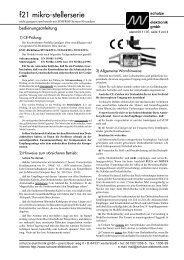
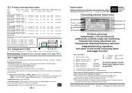
7 External Manual-On Button:<br />
Note: Protect three-pin plug against short<br />
circuits!<br />
Connect the external Manual-On button to the 3-pin plug. If<br />
Manual-On is selected, a short push (less than 1s) on the button will<br />
deactivate the <strong>mcf</strong> <strong>31</strong>/<strong>43</strong>, independent from throttle stick position.<br />
The Manual-On button can also be used as Program-Button.<br />
Warning: With the throttle stick in Power-Off positions (Neutral<br />
or Brake), pressing the button for more than 2s will activate the<br />
<strong>mcf</strong> <strong>31</strong>/<strong>43</strong>!<br />
schulze<br />
elektronik<br />
gmbh<br />
issue 25.3.96, page 4 of 9<br />
8 Tx-Programming for Helicopters:<br />
Steps to be followed before programming the <strong>mcf</strong> <strong>31</strong>/<strong>43</strong> as<br />
described in next chapter.<br />
For a stationary hover an electric helicopter requires usually 75-<br />
85% of available power.<br />
As trim travels or settings on the transmitter are often limited, it<br />
is recommended to offset the neutral position (hover position) by<br />
changing the throttle end point adjustments to 150% (Power-Off)<br />
and 50% (Full Power). This little trick will enable you to use the full<br />
trim range for the final set-up.<br />
9 Programming:<br />
The <strong>mcf</strong> <strong>31</strong>/<strong>43</strong> can be programmed on two levels, Basic Mode<br />
and Feature Mode, to suit your requirements.<br />
In Basic Mode functions are set up to throttle stick positions.<br />
In Feature Mode the characteristics of the <strong>mcf</strong> <strong>31</strong>/<strong>43</strong> can be<br />
modified.<br />
Using the flysoft-program and an interface chord (prog-adapt),<br />
settings can also be changed directly with a PC.<br />
Procedures to enter program modes:<br />
To enter Basic Mode the program button needs to be pressed<br />
while connecting the flight pack. This operation requires "3 hands"<br />
to avoid unintended stick movements.<br />
Feature Mode can (almost) be entered during normal operation.<br />
The <strong>mcf</strong> <strong>31</strong>/<strong>43</strong> must be in the "Ready for Activation" state.<br />
"General Reset" will return the <strong>mcf</strong> <strong>31</strong>/<strong>43</strong> to the factory setup,<br />
suitable for FAI competitions:<br />
9.1) Basic Mode (Travel Adjust / Servo Reverse)<br />
1) For Graupner/JR mc-18 / mc-20 RC-systems<br />
2) Brake and Neutral at the same stick end position.<br />
3) Full Power at the opposite stick end position.<br />
9.2) Feature Mode<br />
1) Current limitation: set for nominal value (lower value than<br />
technical data)<br />
2) Function principle: <strong>speed</strong> control via voltage variation<br />
3) Acceleration: set for minimum softstart<br />
4) Brake: set for immediate stop<br />
5) Activation of the <strong>mcf</strong> <strong>31</strong>/<strong>43</strong> power circuit: set for Auto-On<br />
6) Deactivation of the power circuit: set for near 5V.<br />
schulze elektronik gmbh • prenzlauer weg 6 • D-6<strong>43</strong><strong>31</strong> weiterstadt • tel: 06150/1306-5, fax: 1306-99<br />
internet: http://www.schulze-elektronik.com e-mail: mail@schulze-elektronik.com
<strong>mcf</strong> <strong>31</strong>/<strong>mcf</strong> <strong>43</strong>: <strong>multi</strong> <strong>purpose</strong> <strong>speed</strong> <strong>controllers</strong><br />
with torqe control, microprocessor controlled<br />
user manual<br />
9.1) Basic Mode and "General Reset" (Throttle Stick Travel Adjustment):<br />
schulze<br />
elektronik<br />
gmbh<br />
issue 25.3.96, page 5 of 9<br />
a) Switch on Tx and Rx, <strong>mcf</strong> <strong>31</strong>/<strong>43</strong> powerless, i.e.: flight pack disconnected.<br />
b) Connect Program Button to the 3-pin plug of the <strong>mcf</strong> <strong>31</strong>/<strong>43</strong>. When using the test-meter set (tast-vm) ensure that the brown wire is<br />
next to the negative flight pack wire, also see colour code on the label.<br />
c) Press and hold the Program Button and<br />
d) Connect the flight pack. For a "General Reset" the Program Button must be pressed for 40 seconds! If the travel adjustment for<br />
Graupner/JR suits your RC-system the "General Reset" programming can be finished by disconnecting the flight pack after 40<br />
seconds.<br />
e) Release Program Button.<br />
f) Move throttle stick to position1 Brake position and press Program Button.<br />
g) Move throttle stick to position2 Neutral position** and press Program Button.<br />
h) Move throttle stick to position3 Full-Power position and press Program Button.<br />
i) Programming complete. To select Auto-On move stick to Power-Off positions (Neutral or Brake position).<br />
j) After 1 second the motor beeps and the <strong>mcf</strong> <strong>31</strong>/<strong>43</strong> is activated.<br />
To select Manual-On (Manual activation via separate activation button):<br />
k) Press activation button for more than 2 seconds.<br />
After the motor beeps the <strong>mcf</strong> <strong>31</strong>/<strong>43</strong> is activated.<br />
[**] Usually the same stick position is used for Neutral and Brake. If position1 (Brake) is set between position2 and position3, the brake<br />
function is deactivated. If position2 (Neutral) is set between position1 and position3, windmilling is possible at Neutral position<br />
9.2) Feature Mode (Programming the Characteristics of <strong>mcf</strong> <strong>31</strong>/<strong>43</strong>):<br />
(Basic Mode programming must be completed before entering Feature Mode)<br />
a) Switch on Tx and Rx.<br />
b) Ensure throttle stick is not in Power-Off position (not in Neutral and not in Brake position).<br />
c) Connect Program Button to the 3-pin plug of the <strong>mcf</strong> <strong>31</strong>/<strong>43</strong>. When using the tast-vm ensure that the brown wire is next to the negative<br />
flight pack wire, also see colour code on the label.<br />
d) Connect flight pack. The <strong>mcf</strong> <strong>31</strong>/<strong>43</strong> will not become activated. It will stay "Ready for Activation" ***.<br />
e) Choose function by pressing the Program Button for the given time periods (see next pages).<br />
[***] Note: Two Procedures to get the <strong>mcf</strong> <strong>31</strong>/<strong>43</strong> in the "Ready for Activation" condition:<br />
1) Connect the flight pack while the throttle stick is not in the Power-Off positions (not in Neutral and not in Brake position).<br />
2) If the <strong>mcf</strong> <strong>31</strong>/<strong>43</strong> is activated, press the Program Button to deactivate while the motor is slowly running.<br />
a) With Auto-On selected, it is not possible to deactivate the <strong>mcf</strong> <strong>31</strong>/<strong>43</strong> with the throttle stick in the Power-Off positions. Pressing<br />
the Program Button for more than 2 seconds would automatically reactivate it. Therefore the <strong>mcf</strong> <strong>31</strong>/<strong>43</strong> stays activated.<br />
b) With Manual-On selected, it is possible and intended to deactivate the <strong>mcf</strong> <strong>31</strong>/<strong>43</strong> in the Power-Off positions. Still, to change<br />
settings in Feature Mode, the throttle stick must not be in Neutral or Brake position, because the <strong>mcf</strong> <strong>31</strong>/<strong>43</strong> would become activated<br />
by pressing the Program Button for more than 2 seconds.<br />
schulze elektronik gmbh • prenzlauer weg 6 • D-6<strong>43</strong><strong>31</strong> weiterstadt • tel: 06150/1306-5, fax: 1306-99<br />
internet: http://www.schulze-elektronik.com e-mail: mail@schulze-elektronik.com
<strong>mcf</strong> <strong>31</strong>/<strong>mcf</strong> <strong>43</strong>: <strong>multi</strong> <strong>purpose</strong> <strong>speed</strong> <strong>controllers</strong><br />
with torqe control, microprocessor controlled<br />
user manual<br />
3) After 3s: Setting Current limitation and Function Principle; two steps a and b.<br />
e Red LED on, Green LED off.<br />
9.2.3 To change settings: Release Program Button, Red LED blinks, Green LED off.<br />
Explanation of steps a and b. Programming Sequences start at 9.2.3.1.<br />
a) Current Limitation: Setting the maximum continuous current:<br />
Settings: 1. With the throttle stick in Brake position the old value will be acoustically<br />
indicated. One e corresponds to 10A. (Also see Chapter 10: Control)<br />
2. With a voltmeter connected, the amp value can then be read on the display.<br />
Moving the throttle stick will vary this value. Stick travel from Neutral to<br />
Full Power corresponds to 0-100% current, i.e.: 0-47A for a 47A controller,<br />
0-75A for a 75A controller.<br />
The test volt-meter set shows the amp value calibrated in tenths of the actual value.<br />
With the throttle stick in the appropriate position, press the Program Button<br />
to set the selected value.<br />
schulze<br />
elektronik<br />
gmbh<br />
issue 25.3.96, page 6 of 9<br />
b) Function Principle: Choosing Voltage Control (Standard) or Current Control:<br />
Steps: first step: Throttle stick on Neutral/Brake= 0% power keep old setting<br />
second step e Throttle stick in mid position = 50% power Voltage Control<br />
third step ee Throttle stick on Full Power = 100% power Current Control<br />
Note: In Voltage Control mode, the <strong>mcf</strong> <strong>31</strong>/<strong>43</strong> provides twice the selected current<br />
for about 1.2 seconds at each start of the motor.<br />
Programming Sequence:<br />
9.2.3.1 Select Current Limitation as described under a),<br />
Press Program Button, e Red LED flickers, Green LED flickers.<br />
9.2.3.2 Select Function Principle as described under b),<br />
Press Program Button, e Red LED blinks, Green LED blinks.<br />
9.2.3.3 Move Throttle Stick to Power-Off positions, wait for 1s*,<br />
<strong>mcf</strong> <strong>31</strong>/<strong>43</strong> is activated, e Red LED off, Green LED on.<br />
6) After 6s: Setting Acceleration (Softstart); one step<br />
e Red LED off, Green LED on.<br />
9.2.6 To change settings: Release Program Button Red LED off, Green LED blinks.<br />
Settings: Power-Off (Neutral/Brake) old value<br />
10% power: e 1.5s softstart<br />
100% power 10x e 63ms softstart<br />
9.2.6.1<br />
(Available values: 10% power=1500ms, 1250, 1000, 750, 500, 375, 250, 188, 125, 100% power=63 ms)<br />
Set Acceleration (Softstart),<br />
Press Program Button, e Red LED blinks, Green LED blinks.<br />
9.2.6.2 Move Throttle Stick to Power-Off positions, wait for 1s*,<br />
<strong>mcf</strong> <strong>31</strong>/<strong>43</strong> is activated, e Red LED off, Green LED on.<br />
9) After 9s: Setting Brake Characteristic; one step<br />
e Red LED blinks, Green LED off.<br />
9.2.9 To change settings: Release Program Button Red LED blinks, Green LED off.<br />
Settings: Power-Off: (Neutral/Brake) old value<br />
20% power: e no brake<br />
40% power: ee half brake<br />
60% power: eee soft brake (smooth, for belt drive reductions)<br />
80% power: 4x e dynamic brake (exponentialy increasing power, more smooth than below)<br />
Full Power: 5x e Immediate Stop for FAI competition (Secure spinner and prop!)<br />
9.2.9.1 Select Brake Characteristic,<br />
Press Program Button, e Red LED blinks, Green LED blinks.<br />
9.2.9.2 Move Throttle Stick to Power-Off positions, wait for 1s*,<br />
<strong>mcf</strong> <strong>31</strong>/<strong>43</strong> is activated, e Red LED off, Green LED on.<br />
[*] Wait 1s if Auto-On is selected or press Activation Button for 2-3s if Manual-On is selected.<br />
Note: If the throttle stick is not moved into the Power-Off positions, the <strong>mcf</strong> <strong>31</strong>/<strong>43</strong> will not become activated and the next function can<br />
be programmed. For example: Press the Program Button now for 9s to adjust the Brake Characteristic.<br />
schulze elektronik gmbh • prenzlauer weg 6 • D-6<strong>43</strong><strong>31</strong> weiterstadt • tel: 06150/1306-5, fax: 1306-99<br />
internet: http://www.schulze-elektronik.com e-mail: mail@schulze-elektronik.com
<strong>mcf</strong> <strong>31</strong>/<strong>mcf</strong> <strong>43</strong>: <strong>multi</strong> <strong>purpose</strong> <strong>speed</strong> <strong>controllers</strong><br />
with torqe control, microprocessor controlled<br />
user manual<br />
schulze<br />
elektronik<br />
gmbh<br />
issue 25.3.96, page 7 of 9<br />
12) after 12s: Setting Activation Mode and Low Voltage Cut-Off, two steps a) and b).<br />
e Red LED off, Green LED blinks<br />
9.2.12 To change settings: Release Program Button Red LED off, Green LED blinks.<br />
a) Activation Mode (Auto-On or Manual-On via separate activation button):<br />
Settings: Throttle stick on Power-Off = 0% power keep old setting<br />
Throttle stick in mid position = 50% power e Manual-On<br />
Throttle stick on Full Power = 100% power ee Auto-On<br />
b) Low Voltage Motor-Off (with previous power reduction below 50%):<br />
Settings: Throttle stick on Power-Off = 0% power keep old setting<br />
Throttle stick in mid position = 50% power e Motor-Off determined by battery voltage and current.<br />
Throttle stick on Full Power = 100% power ee Motor-Off at 5V<br />
9.2.12.1 Select Activation Mode as described under a),<br />
Press Program Button,<br />
9.2.12.2 Select Low Voltage Motor-Off as described under b)<br />
e Red LED flickers, Green LED flickers.<br />
Press Program Button, e Red LED flickers, Green LED blinks.<br />
9.2.12.3 Move Throttle Stick to Power-Off positions, wait for 1s*,<br />
<strong>mcf</strong> <strong>31</strong>/<strong>43</strong> is activated, e Red LED off, Green LED on.<br />
15) After 15s: Calibration control of the test-voltmeter set; no step, display function only.<br />
(end) e Red LED off, Green LED off;<br />
9.2.15 Release Program Button Red LED off, Green LED off.<br />
The test-voltmeter should be in mid position, i.e. showing 0.5V.<br />
9.2.15.1 Press Program Button, e Red LED blinks, Green LED blinks.<br />
9.2.15.2 Move Throttle Stick to Power-Off positions, wait for 1s*,<br />
<strong>mcf</strong> <strong>31</strong>/<strong>43</strong> is activated, e Red LED off, Green LED on.<br />
[*] Wait 1s if Auto-On is selected or press Activation Button for 2-3s if Manual-On is selected.<br />
Note: If the throttle stick is not moved into the Power-Off positions (Neutral and/or Brake), the <strong>mcf</strong> <strong>31</strong>/<strong>43</strong> will not become activated<br />
and the next function can be programmed. For example: Press the Program Button now for 6s to set the Acceleration.<br />
10 Setup Controls:<br />
LED-Monitor<br />
red / green blinking "Ready for Activation"<br />
green flickering Brake activated<br />
green variable intensity Brightness reverse proportional to Motor Voltage<br />
green dark to bright Full Power Position reached<br />
red continuously on Temperature overload or Low-voltage switch-off<br />
LED-Monitor and Acoustic signals<br />
Red and continuous-e after setup: Insufficient stick travel between Power-Off and Full Power<br />
During Programming in Feature Mode: e as described in previous chapters.<br />
Acoustic Signals<br />
long e Indicates activation of <strong>speed</strong> controller<br />
short e When pressing button in Feature Mode (not in Basic Mode)<br />
several e When moving throttle stick from Power to Power-Off position in Feature Mode.<br />
Will indicate old settings.<br />
Voltmeter Values displayed in Feature Mode only!<br />
With the throttle stick in Power-Off position, the old settings are displayed after the acoustic<br />
signals (not simultaneously). Moving the throttle stick will show available values selectable<br />
by pressing the Program Button.<br />
11 Current (Torque) Control:<br />
Selecting Torque-Control will automatically shift the programmed max. current value to the Full Power stick position.<br />
The throttle stick will now proportionally control the motor current, i.e. stick in mid position = 50% of the programmed max. current<br />
(not 50% of the nominal value of the <strong>speed</strong> controller).<br />
schulze elektronik gmbh • prenzlauer weg 6 • D-6<strong>43</strong><strong>31</strong> weiterstadt • tel: 06150/1306-5, fax: 1306-99<br />
internet: http://www.schulze-elektronik.com e-mail: mail@schulze-elektronik.com
<strong>mcf</strong> <strong>31</strong>/<strong>mcf</strong> <strong>43</strong>: <strong>multi</strong> <strong>purpose</strong> <strong>speed</strong> <strong>controllers</strong><br />
with torqe control, microprocessor controlled<br />
user manual<br />
schulze<br />
elektronik<br />
gmbh<br />
issue 25.3.96, page 8 of 9<br />
Initially motor control in torque-control mode does not differ from conventional <strong>speed</strong> control until the set current is reached and kept<br />
at this value. If a very high max. current was programmed, the change from conventional- to torque-control will take place before reaching<br />
Full Power, usually at mid position to allow for a smooth transfer. Back in the Power-Off position, torque-control will return to<br />
conventional control. To avoid unwanted control mode changes, move throttle trim towards Full Power.<br />
Note: Extra smooth control can be achieved by selecting minimum acceleration = maximum softstart = 1.5s.<br />
12 Installation Instructions<br />
Using other than reverse polarity protected connectors will void your warranty. Suitable for up to 35A are Gold 2mm (with limitations),<br />
Gold 2.5mm or the green MPX 6-pin systems. For higher currents 4mm systems like the Conzelmann CT4 may be used (available as<br />
accessory).<br />
Soldering instructions for <strong>mcf</strong> <strong>31</strong>/<strong>43</strong> cables to 4mm (CT4) connectors:<br />
<strong>mcf</strong> battery+: feed red cable from the rear through the tighter red tube of the double housing, solder (female) socket and press it in*<br />
<strong>mcf</strong> battery -: feed black cable from the rear through the wider tube of the double housing, solder (male) pin and press it in*<br />
<strong>mcf</strong> motor +: feed red cable from the rear through the wider yellow tube of a split double housing**, solder pin and press it in*<br />
<strong>mcf</strong> motor - : feed black cable through the wider yellow tube of a split double housing**, solder pin and press it in*<br />
please use red housings at cables of accumulator pack and yellow housings at cables of your motor.<br />
[*] For correct installation of connectors we recommend to use a parallel vice and a hammer.<br />
Damage to the socket during installation can be avoided by leaving a single pin inserted.<br />
[**] The cut-off tighter housing halves are used to insulate the sockets soldered to the motor cables.<br />
If motors with integrated sockets are used, the leftover housing halves are replaced by yellow heat shrink tubing.<br />
Whenever possible the motor should be directly soldered to the motor cables (red and yellow of the <strong>mcf</strong> <strong>31</strong>/<strong>43</strong>). Keep the length<br />
of the cables short to reduce EMI emissions!<br />
To change the direction of motor rotation simply swap the motor cables. Never reverse the battery cables!<br />
Avoid excessive heat built-up of packing the <strong>mcf</strong> <strong>31</strong>/<strong>43</strong>. Fix it with Velcro! Do not pack in foam rubber.<br />
13 Warranty:<br />
All <strong>mcf</strong> <strong>31</strong> and/or <strong>mcf</strong> <strong>43</strong> have been examined carefully before the delivery under working conditions with accumulators and a motor.<br />
If you should have reason for complaint, please send the device back to us with a clear error description. The text "No 100% function"<br />
is not enough! Test the <strong>mcf</strong> <strong>31</strong>/<strong>43</strong> carefully once more before returning it. If our tests show no problem with your device, you have to pay<br />
the costs of our testing. This applies whether the device was sent back within the time of warranty or later.<br />
Hint: If you have a problem with a device of ours, please send it directly back to us without previously solering it in. This way the results<br />
of repair are the fastest, the costs remain low and guarantee errors are recognized without doubt. Then you can be sure too, that only original<br />
parts will be inserted (We have already had bad experiences with alleged service stations). Previous repairs outside of our firm and/or by<br />
improper repair can no longer be estimated. A repair of such devices may possibly be refused by us.<br />
14 Technical Data:<br />
Item Current Ni-Cd Dimensions Weight Cables RDSon Losses Brake Comments<br />
Type [A] [Cells] [mm] [g] [mm 2 ] [mW] [mV/10A] [mW]<br />
<strong>mcf</strong><strong>31</strong>-47be 47(60)/95 6-12 41 x <strong>31</strong> x 11 21-55 2.5 3.3 32 10 BEC 5.2V/2.5A peak<br />
<strong>mcf</strong><strong>31</strong>-47bo 47(60)/95 6-16 41 x <strong>31</strong> x 11 21-55 2.5 3.3 32 10 Opto-coupler<br />
<strong>mcf</strong><strong>31</strong>-52bo 52(60)/105 10-24 41 x <strong>31</strong> x 11 21-55 2.5 2.7 36 8 Opto-coupler<br />
<strong>mcf</strong><strong>43</strong>-70be 70(90)/140 6-12 52 x <strong>31</strong> x 11 33-65 4.0 2.5 24 3.3 BEC 5.2V/2.5A peak<br />
<strong>mcf</strong><strong>43</strong>-75bo 75(90)/150 6-32 52 x <strong>31</strong> x 11 33-65 4.0 2 24 5.3 Opto-coupler<br />
<strong>mcf</strong><strong>43</strong>-110bo 110(130)/180 6-32 52 x <strong>31</strong> x 11 33-65 4.0 2 24 2.6 Opto-coupler<br />
Temperature overload at about 110 °C, Switching Frequency about 2.0 kHz<br />
Current: Nominal Current (increased Current) / Maximum Current:<br />
All <strong>mcf</strong> <strong>31</strong>/<strong>43</strong> can be operated at Full Power and Nominal Current for the time period of a 2Ah (1Ah for <strong>mcf</strong><strong>43</strong>-110bo) battery dischharge<br />
cycle. The Maximum Current is the peak value. This value decreases linearly with the Nominal Current value within 1.2s after motor start.<br />
If you will set 30A for Nominal Current, Maximum Current will be 2x30A=60A.<br />
Current limitations are slightly effected by temperature and can be a bit higher if the <strong>mcf</strong> <strong>31</strong>/<strong>43</strong> is cold and lower, if the <strong>mcf</strong> <strong>31</strong>/<strong>43</strong> is warm.<br />
RDSon, Brake: Internal full <strong>speed</strong> on Resistance of the transistors, calculated from data sheets.<br />
Losses: Typical figures measured at 13V, 30A and 25°C controller temperature.<br />
Measured using pin needles between battery (-) and motor (+) close to the controller circuit board.<br />
tast-vm test-voltmeter set: Program Button in combination with a litte analog voltage meter to display the currents<br />
to be programmed.<br />
flysoft PC-Software to read out data, modify data and program it back to <strong>mcf</strong> <strong>31</strong> & <strong>mcf</strong> <strong>43</strong> bit-accurate.<br />
prog-adapt active programming adapter (PC <strong>mcf</strong> <strong>31</strong> & <strong>mcf</strong> <strong>43</strong>) with three cables.<br />
schulze elektronik gmbh • prenzlauer weg 6 • D-6<strong>43</strong><strong>31</strong> weiterstadt • tel: 06150/1306-5, fax: 1306-99<br />
internet: http://www.schulze-elektronik.com e-mail: mail@schulze-elektronik.com
<strong>mcf</strong> <strong>31</strong>/<strong>mcf</strong> <strong>43</strong>: <strong>multi</strong> <strong>purpose</strong> <strong>speed</strong> <strong>controllers</strong><br />
with torqe control, microprocessor controlled<br />
user manual<br />
15 Programming Examples:<br />
(Basic Mode programming must be completed.)<br />
1) Task description: Change acceleration setup<br />
to 1s softstart:<br />
a) Turn on the transmitter and the receiver.,<br />
b) Throttle stick must not be in Neutral / Brake position.<br />
c) Connect Program Button with the <strong>mcf</strong> <strong>31</strong>/<strong>43</strong>;<br />
d) Connect flight battery pack,<br />
the <strong>mcf</strong> <strong>31</strong>/<strong>43</strong> will not become activated,<br />
it will be in Ready for Activation condition,<br />
i.e. both LEDs will blink alternately.<br />
e) Press Program Button for 6s:<br />
After 3s e, Red LED on, Green LED off.<br />
After +3s e, Red LED off, Green LED on.<br />
f) Release Program Button.<br />
Green LED starts to blink very fast, and the <strong>mcf</strong> <strong>31</strong>/<strong>43</strong><br />
is ready for Softstart Mode Setup.<br />
g) Move throttle stick to 30% power position.,<br />
According to Chapter 9.6.: 1000 ms, i.e. 1 second.<br />
h) Press Program Button (short press).<br />
Red LED and Green LED will blink alternately,<br />
i.e. the <strong>mcf</strong> <strong>31</strong>/<strong>43</strong> is Ready for Activation.<br />
i) Programmimng is complete. To check programming, move<br />
throttle Stick into Power-Off position and wait for about 1s.<br />
The <strong>mcf</strong> <strong>31</strong>/<strong>43</strong> will become activated,<br />
e Red LED off, Green LED on.<br />
j) Hold Model firmly and ensure safety distance from propeller.<br />
Move throttle stick quickly into Full Power position.<br />
The motor should reach Full Power within 1s.<br />
k) Move throttle stick into Brake position.<br />
Motor stops, check completed.<br />
2) Task description: Change acceleration setup<br />
to 60ms softstart:<br />
Follow all steps as described under 1) except step g).<br />
For max. accelereation = min. softstart the throttle stick must be<br />
moved to Full Power during step g).<br />
3) Task description: Setting Current Limitation<br />
to 20A:<br />
a) Turn on the transmitter and the receiver.,<br />
b) Throttle stick must not be in Neutral / Brake position.<br />
c) Connect Program Button with the <strong>mcf</strong> <strong>31</strong>/<strong>43</strong>;<br />
d) Connect flight battery pack,<br />
the <strong>mcf</strong> <strong>31</strong>/<strong>43</strong> will not become activated,<br />
it will be in Ready for Activation condition,<br />
i.e. both LEDs will blink alternately.<br />
e) Press Program Button for 3s:<br />
After 3s e, Red LED on, Green LED off.<br />
f) Release Program Button.<br />
Red LED starts to blink very fast, and the <strong>mcf</strong> <strong>31</strong>/<strong>43</strong><br />
is ready for Current Limitation Setup.<br />
g) Move throttle stick to 40% power position<br />
(50A controller type, e.g. <strong>mcf</strong> <strong>31</strong>-47be),<br />
or to 20% power position<br />
(100A controller type, e.g. <strong>mcf</strong> <strong>43</strong>-110bo).<br />
If the tast-vm is used it will show: 2 = 200mV = 20A.<br />
h) Press Program Button (short press).<br />
Red and Green LED are flickering, i.e. the <strong>mcf</strong> <strong>31</strong>/<strong>43</strong><br />
is ready for Control Mode Setup.<br />
schulze<br />
elektronik<br />
gmbh<br />
issue 25.3.96, page 9 of 9<br />
i) To keep the old control mode the throttle stick must be in<br />
Power-Off position (Neutral / Brake).<br />
If the tast-vm is used, it will show:<br />
10 = 1V = 100% Power = conventional Voltage Control.<br />
j) Press Program Button (short press).<br />
Red LED and Green LED will blink alternately,<br />
i.e. the <strong>mcf</strong> <strong>31</strong>/<strong>43</strong> is Ready for Activation.<br />
k) Programmimng is complete. To check programming, move<br />
throttle Stick into Power-Off position and wait for about 1s.<br />
The <strong>mcf</strong> <strong>31</strong>/<strong>43</strong> will become activated,<br />
e Red LED off, Green LED on.<br />
l) Hold Model firmly and ensure safety distance from propeller<br />
Move throttle stick slowly into Full Power position.<br />
A motor which would normally draw 50A will now run<br />
with less then half power as the current is limited to 20A<br />
m) Move throttle stick into Brake position.<br />
Motor stops, check completed.<br />
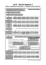
16 Accessories / Connections:<br />
Each <strong>mcf</strong> <strong>31</strong>/<strong>43</strong> comes with a small circuit board carrying a<br />
micro button for programming.<br />
A combined Manual-On / Program Button with a 15cm lead for<br />
fuselage installation is available separately (ptaster).<br />
Also available is the test-voltmeter set (tast-vm), a programming<br />
tool with button and mini voltmeter for visual indication.<br />
Instead of using the tast-vm a commercial voltmeter can be used<br />
to show the programmed values. Range to be set for 2V max.<br />
You can adjust <strong>mcf</strong> <strong>31</strong>/<strong>43</strong> with flysoft, a program for Your<br />
laptop computer. All programming possibilities you find in this<br />
user manual are possible. Plus the possibility to read out programmed<br />
data from the <strong>mcf</strong> <strong>31</strong>/<strong>43</strong> (to modify them) and then program<br />
it back to it.<br />
The cable to link PC and <strong>mcf</strong> <strong>31</strong>/<strong>43</strong> is our prog-adapt<br />
(programming adapter). It is an active one with three connectors to<br />
connect receiver and <strong>speed</strong> controller.<br />
schulze elektronik gmbh • prenzlauer weg 6 • D-6<strong>43</strong><strong>31</strong> weiterstadt • tel: 06150/1306-5, fax: 1306-99<br />
internet: http://www.schulze-elektronik.com e-mail: mail@schulze-elektronik.com<br />
+<br />
V<br />
-<br />
(orange)<br />
(brown)<br />
+ battery<br />
servolead<br />
inner pin<br />
outer pin<br />
- battery<br />
<strong>mcf</strong> <strong>31</strong>/<strong>mcf</strong> <strong>43</strong>