mcc-eagle: professional speed controller for rc-cars
mcc-eagle: professional speed controller for rc-cars
mcc-eagle: professional speed controller for rc-cars

Create successful ePaper yourself
Turn your PDF publications into a flip-book with our unique Google optimized e-Paper software.
<strong>mcc</strong>-<strong>eagle</strong>: <strong>professional</strong> <strong>speed</strong> <strong>controller</strong> <strong>for</strong> <strong>rc</strong>-<strong>cars</strong><br />
preliminary operating instructions <strong>for</strong> software V11, date of issue 11 APR 2000<br />
1<br />
2<br />
6 5<br />
3<br />
4<br />
9<br />
7<br />
8<br />
10<br />
schulze<br />
elektronik<br />
gmbh<br />
page 1<br />
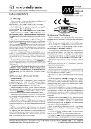
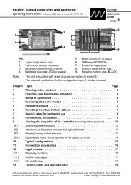
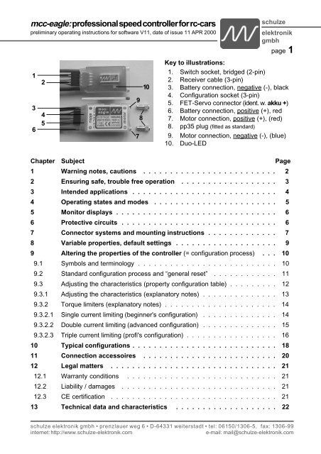
Key to illustrations:<br />
1. Switch socket, bridged (2-pin)<br />
2. Receiver cable (3-pin)<br />
3. Battery connection, negative (-), black<br />
4. Configuration socket (3-pin)<br />
5. FET-Servo connector (ident. w. akku +)<br />
6. Battery connection, positive (+), red<br />
7. Motor connection, positive (+), (red)<br />
8. pp35 plug (fitted as standard)<br />
9. Motor connection, negative (-), (blue)<br />
10. Duo-LED<br />
Chapter Subject Page<br />
1 Warning notes, cautions . . . . . . . . . . . . . . . . . . . . . . . . . 2<br />
2 Ensuring safe, trouble free operation . . . . . . . . . . . . . . . . . . 3<br />
3 Intended applications . . . . . . . . . . . . . . . . . . . . . . . . . . . 4<br />
4 Operating states and modes . . . . . . . . . . . . . . . . . . . . . . . 5<br />
5 Monitor displays . . . . . . . . . . . . . . . . . . . . . . . . . . . . . . 6<br />
6 Protective ci<strong>rc</strong>uits . . . . . . . . . . . . . . . . . . . . . . . . . . . . . 6<br />
7 Connector systems and mounting instructions . . . . . . . . . . . . . 7<br />
8 Variable properties, default settings . . . . . . . . . . . . . . . . . . . 9<br />
9 Altering the properties of the <strong>controller</strong> (= configuration process) . . . 10<br />
9.1 Symbols and terminology . . . . . . . . . . . . . . . . . . . . . . . . . . 10<br />
9.2 Standard configuration process and “general reset” . . . . . . . . . . . . 11<br />
9.3 Adjusting the characteristics (property configuration table) . . . . . . . . . 12<br />
9.3.1 Adjusting the characteristics (explanatory notes) . . . . . . . . . . . . . . 13<br />
9.3.2 Torque limiters (explanatory notes) . . . . . . . . . . . . . . . . . . . . . 14<br />
9.3.2.1 Single current limiting (beginner's configuration) . . . . . . . . . . . . . . 14<br />
9.3.2.2 Double current limiting (advanced configuration) . . . . . . . . . . . . . . 15<br />
9.3.2.3 Triple current limiting (profi's configuration) . . . . . . . . . . . . . . . . . 16<br />
10 Typical configurations . . . . . . . . . . . . . . . . . . . . . . . . . . . 18<br />
11 Connection accessoires . . . . . . . . . . . . . . . . . . . . . . . . . 20<br />
12 Legal matters . . . . . . . . . . . . . . . . . . . . . . . . . . . . . . . 21<br />
12.1 Warranty conditions . . . . . . . . . . . . . . . . . . . . . . . . . . . . 21<br />
12.2 Liability / damages . . . . . . . . . . . . . . . . . . . . . . . . . . . . . 21<br />
12.3 CE certification . . . . . . . . . . . . . . . . . . . . . . . . . . . . . . . 21<br />
13 Technical data and characteristics . . . . . . . . . . . . . . . . . . . 22<br />
schulze elektronik gmbh • prenzlauer weg 6 • D-64331 weiterstadt • tel: 06150/1306-5, fax: 1306-99<br />
internet: http://www.schulze-elektronik.com e-mail: mail@schulze-elektronik.com
page 2<br />
1 Warning notes, cautions<br />
Electric motors fitted with propellers are dangerous<br />
and require proper care <strong>for</strong> safe operation.<br />
Keep well clear of the rotating parts at all<br />
times when the battery pack is connected.<br />
Technical defects of an electrical or mechanical<br />
nature may result in unintended motor runs;<br />
loose parts may cause serious personal injuriy<br />
and/or property damage.<br />
The CE-certificate on the <strong>speed</strong> <strong>controller</strong> does<br />
not absolve you from taking proper care<br />
when handling the system!<br />
Speed <strong>controller</strong>s are exclusively <strong>for</strong> use in RC<br />
models. Their use in man-carrying ai<strong>rc</strong>raft is<br />
prohibited.<br />
Speed <strong>controller</strong>s and softswitches are not protected<br />
against reverse polarity (+ terminal<br />
and - terminal reversed). Connecting the<br />
battery pack to the motor leads of the <strong>controller</strong><br />
or soft-switch will almost certainly<br />
cause irreparable damage.<br />
Electronic equipment is sensitive to humidity.<br />
Speed <strong>controller</strong>s and soft-switches which<br />
have got wet may not function properly even<br />
after thorough drying. You should send<br />
them back to us <strong>for</strong> cleaning and testing.<br />
Do not use <strong>speed</strong> <strong>controller</strong>s in conjunction with<br />
a power supply connected to the mains. Energy<br />
reversal can occur when the motor slows<br />
down and stops, and this may damage the<br />
power supply or cause an over-voltage condition<br />
which could damage the <strong>controller</strong>.<br />
Never disconnect the flight pack while the motor<br />
is running, as this could cause damage<br />
on a <strong>speed</strong> <strong>controller</strong> or a soft-switch.<br />
On no account connect a separate receiver battery<br />
or an electronic battery switch (two receiver<br />
batteries), as this may cause damage<br />
to the <strong>speed</strong> <strong>controller</strong> and could cause current<br />
to flow from the receiver battery to the<br />
motor. If you want to use a separate receiver<br />
battery cut through the + wire in the receiver<br />
cable, or pull it out of the connector if<br />
possible. However, <strong>for</strong> greater protection<br />
against motor-inducted interference it is always<br />
better to use a <strong>speed</strong> <strong>controller</strong> with<br />
an opto-coupler.<br />
<strong>mcc</strong>-<strong>eagle</strong>: <strong>professional</strong> <strong>speed</strong> <strong>controller</strong> <strong>for</strong> <strong>rc</strong>-<strong>cars</strong><br />
Protect the <strong>speed</strong> <strong>controller</strong> or soft-switch from<br />
mechanical loads, vibration, dirt and contamination.<br />
Keep the cables to the battery and to the motor<br />
as short as possible.<br />
Never leave the drive battery connected when ...<br />
... the model is not in use and/or<br />
... the battery pack is being charged.<br />
(Although some <strong>speed</strong> <strong>controller</strong>s feature a<br />
separate On/Off switch, this does not isolate<br />
it completely from the battery.)<br />
Protect the 3-pin configuration input and FET<br />
servo connector pin from short-ci<strong>rc</strong>uit.<br />
Note the limited capacity of the BEC system<br />
when used with high current load and/or a<br />
high number of cells in the flight pack (see<br />
Section 13).<br />
Speed <strong>controller</strong>s and soft-switches can only<br />
function properly if they are in full working<br />
condition. The protective and monitoring ci<strong>rc</strong>uits<br />
can also only work if the <strong>speed</strong> <strong>controller</strong><br />
is in good operating condition.<br />
In the case of motor failure (e.g.short<br />
ci<strong>rc</strong>uits in the windings) the over-temperature<br />
sensor in the <strong>controller</strong>s may<br />
react too slowly to prevent damage.<br />
Switch the motor off immediately to<br />
prevent permanent damage to the<br />
<strong>speed</strong> <strong>controller</strong>.<br />
If a transistor fails in the throttle stage,<br />
neither a "stop" signal from the transmitter<br />
nor the temperature monitor nor<br />
the current limiter will be able to throttle<br />
back or stop the motor.<br />
Note: Please remember that the monitoring ci<strong>rc</strong>uits<br />
are unable to detect every abnormal<br />
operating condition, such as a short between<br />
the motor cables. Note also that a<br />
stalled motor will only trip the current limiter<br />
if the motor's stall current is well above the<br />
<strong>controller</strong>'s peak current. For example, if<br />
you are using an 80 A <strong>controller</strong> in conjunction<br />
with a 20 A motor, the current monitor<br />
will not detect an excessive current even<br />
when the motor is stalled.<br />
schulze elektronik gmbh • prenzlauer weg 6 • D-64331 weiterstadt • tel: 06150/1306-5, fax: 1306-99<br />
internet: http://www.schulze-elektronik.com e-mail: mail@schulze-elektronik.com
<strong>mcc</strong>-<strong>eagle</strong>: <strong>professional</strong> <strong>speed</strong> <strong>controller</strong> <strong>for</strong> <strong>rc</strong>-<strong>cars</strong><br />
preliminary operating instructions <strong>for</strong> software V11, date of issue 11 APR 2000<br />
2 Ensuring safe, trouble-free<br />
operation<br />
Use only compatible connectors. A 2mm pin<br />
cannot provide reliable contact in a 2.5mm<br />
socket. The same applies with 2mm goldcontact<br />
pins and 2mm tin-plated sockets.<br />
Please also remember that ...<br />
... the wiring of your RC-components must be<br />
checked regularly <strong>for</strong> loose wires, oxidation,<br />
or damaged insulation, especially when<br />
using a BEC system.<br />
... your motor is suppressed by at least two,<br />
better: three, ceramic capacitors of 10 to<br />
100nF / 63 to 100V. Extra suppression can<br />
also be achieved using filters with coils.<br />
... the CE certificate on the <strong>speed</strong> <strong>controller</strong><br />
does not absolve you from the need to handle<br />
the system carefully.<br />
... your receiver and the aerial must be at least<br />
3 cm (>1") away from motor, <strong>speed</strong><br />
<strong>controller</strong> and high-current cables. For<br />
example, the magnetic fields around<br />
the high-current cables can cause interference<br />
to the receiver (particularly<br />
when <strong>speed</strong>ing up).<br />
... Sie bei der Verwendung eines FET-Servos<br />
die dort beiliegende Drossel auch wirklich<br />
nach Vorschrift verwenden.<br />
... all high-current cables must be as short as<br />
possible. Maximum length between flight<br />
pack and <strong>speed</strong> <strong>controller</strong> should not exceed<br />
20 cm (7"), between <strong>speed</strong> <strong>controller</strong> and<br />
motor: 5 cm (2").<br />
... all high-current cables longer than 5 cm (2")<br />
must be twisted together. This applies in particular<br />
to the motor power cables, which are<br />
very powerful sou<strong>rc</strong>es of radiated interference.<br />
... in model <strong>cars</strong>: the aerial must be deployed<br />
carefully - unless you are using a whip aerial.<br />
Fold up the aerial close to the receiver and<br />
slip the end into a plastic tube mounted vertically<br />
in the model.<br />
... in model boats: half of the receiver aerial's<br />
length should be deployed inside the hull<br />
above the waterline, the other half should be<br />
threaded into a small tube mounted upright.<br />
schulze<br />
elektronik<br />
gmbh<br />
page 3<br />
Every time you intend to use the power system<br />
- be<strong>for</strong>e you turn on the receiver -<br />
make sure that ...<br />
... no one else is using the same frequency<br />
(identical channel number).<br />
... your transmitter is switched on and the<br />
throttle stick is in the STOP position.<br />
Carry out a range check be<strong>for</strong>e each drive. Collapse<br />
the transmitter aerial. Walk away from<br />
the model to the distance stated by the RC<br />
system manufacturer (this might be a distance<br />
of about 25-30 m = 100'). Make sure<br />
that you still have full control of the system<br />
at this range.<br />
As a general rule: receiver interference is<br />
more likely to occur when using a <strong>controller</strong><br />
with BEC system, as these units do not feature<br />
an opto-coupler with its optical link.<br />
When Ni-Cd batteries approach the end of their<br />
charge, voltage falls drastically and quickly.<br />
The <strong>mcc</strong>-<strong>eagle</strong> detects this and reduces<br />
power to the motor automatically. This<br />
should leave sufficient energy to bring your<br />
model back home. However, if you use a<br />
small number of cells of high internal resistance<br />
and operate at high motor currents,<br />
the <strong>controller</strong> may reduce power be<strong>for</strong>e the<br />
pack is discharged. You can eliminate this<br />
problem by using low resistance straps to<br />
connect the cells, or use the direct cell-tocell<br />
soldering technique (“sticks”) and short,<br />
heavy-gauge wire if you assemble your own<br />
batteries.<br />
Your receiver also benefits from the stability of<br />
the voltage supplied from the battery. If the<br />
BEC voltage is stable, the receiver is less<br />
liable to suffer interference. For this reason,<br />
BEC voltage can be switched between two<br />
voltages (see Section 9.3.1).<br />
Incidental note - definitions:<br />
Our range includes both standard <strong>speed</strong> <strong>controller</strong>s<br />
and genuine <strong>speed</strong> regulators, which are capable of<br />
maintaining a constant motor <strong>speed</strong> even when the<br />
load varies. To differentiate between the two types<br />
our instructions always use the term “<strong>speed</strong> <strong>controller</strong>”<br />
<strong>for</strong> “standard” units which simply provide proportional<br />
control of motor <strong>speed</strong>, and reserve the term<br />
“regulator” <strong>for</strong> constant <strong>speed</strong> units.<br />
schulze elektronik gmbh • prenzlauer weg 6 • D-64331 weiterstadt • tel: 06150/1306-5, fax: 1306-99<br />
internet: http://www.schulze-elektronik.com e-mail: mail@schulze-elektronik.com
page 4<br />
3 Intended Applications<br />
Since the <strong>mcc</strong>-<strong>eagle</strong> + is of lightweight open<br />
construction, the preferred application is<br />
track-racing <strong>cars</strong>.<br />
<strong>mcc</strong>-<strong>eagle</strong>3 makes use of high per<strong>for</strong>mance<br />
trench technology cool-MOSFETs <strong>for</strong> lowest<br />
losses and highest per<strong>for</strong>mance. For this<br />
reason <strong>mcc</strong>-<strong>eagle</strong>3 is a perfect fit <strong>for</strong> 3000<br />
mAh cells.<br />
Don’t <strong>for</strong>get that weight and space are at a premium<br />
in model car racing, particularly if you<br />
specialise in 1:12 <strong>cars</strong> and the Pro-10 class.<br />
Recommended motors, new minimum specification:<br />
approx. 10/8 turns <strong>for</strong> 1:10 on-road,<br />
approx. 10/8 turns <strong>for</strong> Monster 1:10 off-road,<br />
approx. 11-13/9-11 turns <strong>for</strong> 4-WD off-road,<br />
depending on how the car is set up.<br />
Highlights:<br />
In-line design and a “<strong>controller</strong> instead of cable”<br />
philosophy provide maximum pressure and a<br />
further substantial weight saving.<br />
Ultra-small, ultra-light units due to absence of<br />
cooling fins.<br />
A crucial point <strong>for</strong> all drivers who require maximum<br />
per<strong>for</strong>mance combined with minimum<br />
weight.<br />
Fastest possible response to throttle commands<br />
(it’s your transmitter that slows you down!).<br />
Better than 400-step resolution over the whole<br />
throttle stick range <strong>for</strong> extremely fine <strong>speed</strong><br />
control.<br />
Controllers work reliably right down to the last<br />
scrap of energy in the battery pack.<br />
DUO LED monitor system.<br />
Brake light output.<br />
“Auto-arm” function and “power-on reset”.<br />
“Quick plug-in” - qpi - system features integral<br />
high-current sockets and receiver cable sokket<br />
to allow motor or <strong>speed</strong> <strong>controller</strong> to be<br />
changed quickly and easily.<br />
Plug-in push-button allows full configuration<br />
procedure; alternatively use the “<strong>cars</strong>oft” program<br />
from your PC or notebook. No pots!<br />
During the configuration process the motor acts<br />
as a loudspeaker to give you audible confirmation<br />
of each process.<br />
<strong>mcc</strong>-<strong>eagle</strong>: <strong>professional</strong> <strong>speed</strong> <strong>controller</strong> <strong>for</strong> <strong>rc</strong>-<strong>cars</strong><br />
Configured data can be read-out by “<strong>cars</strong>oft”,<br />
stored on a PC / notebook, fine-tuned on the<br />
computer, and then read back into the <strong>controller</strong>.<br />
Configured data is retained in the unit even<br />
when the battery is disconnected.<br />
Specification:<br />
Function: <strong>speed</strong> <strong>controller</strong><br />
Separation of receiver and load current ci<strong>rc</strong>uit:<br />
no; due to integral BEC system.<br />
Low weight: due to compact<br />
construction and super low-profile cool-FETs.<br />
No. of cells, cell type: 6 to 8 Ni-Cd cells<br />
Low voltage threshold: at approx. 5V<br />
Intended application: maximum per<strong>for</strong>mance<br />
models<br />
Special features:<br />
- integral voltage converter produces an auxiliary<br />
voltage <strong>for</strong> the Power MOS FETs, resulting<br />
in ultra-low losses.<br />
- Super high-capacity BEC ci<strong>rc</strong>uit (peak current<br />
more than 3A)<br />
- Switchable BEC voltage<br />
Allows the use of receivers which are sensitive<br />
to fluctuations in BEC-generated operating<br />
voltage.<br />
- High 2 kHz pulse frequency, keeping the motor<br />
and <strong>controller</strong> cool, shielding the receiver<br />
system from interference and providing optimum<br />
acceleration and braking characteristics.<br />
- Turbo-start function<br />
- Maximum resolution in throttle + brake range.<br />
- Sophisticated triple current limiter system<br />
- Minimum throttle function<br />
- Automatic brake function<br />
- Finely controllable proportional brake with high<br />
pulse rate, variable min. and max. parameters<br />
- ABS<br />
- It is usually possible to prevent the vehicle skidding<br />
during braking by implementing one of the<br />
3 versions of ABS, or by reducing the maximum<br />
braking power; however, the effectiveness of<br />
these functions varies according to track surface<br />
quality, vehicle tyres and vehicle weight.<br />
Super-light, super-small, super-low-profile, super-efficient:<br />
All in all - a really cool <strong>speed</strong> <strong>controller</strong>!<br />
schulze elektronik gmbh • prenzlauer weg 6 • D-64331 weiterstadt • tel: 06150/1306-5, fax: 1306-99<br />
internet: http://www.schulze-elektronik.com e-mail: mail@schulze-elektronik.com
<strong>mcc</strong>-<strong>eagle</strong>: <strong>professional</strong> <strong>speed</strong> <strong>controller</strong> <strong>for</strong> <strong>rc</strong>-<strong>cars</strong><br />
preliminary operating instructions <strong>for</strong> software V11, date of issue 11 APR 2000<br />
4 Operating states and modes<br />
“Awaiting command” status<br />
This condition applies if you:<br />
- connect the <strong>mcc</strong>-<strong>eagle</strong> to the battery when<br />
the transmitter throttle stick is in the “motor<br />
on” range<br />
or<br />
- press the command button when the motor is<br />
running slowly, if the <strong>mcc</strong>-<strong>eagle</strong> is already armed.<br />
Display: both LEDs flash slowly and alternately<br />
“Armed” status (ready to use):<br />
In this condition the <strong>mcc</strong>-<strong>eagle</strong> can control the<br />
motor according to the default or configured<br />
characteristics.<br />
The <strong>mcc</strong>-<strong>eagle</strong> is armed if the ”auto-arm”<br />
function applies when you connect the battery<br />
and switch on the operating voltage, or when<br />
a re-configuration procedure is completed.<br />
Display:<br />
Throttle stick at neutral: both LEDs flash fast<br />
and alternately.<br />
Throttle stick at brake position: green LED flashes<br />
fast.<br />
“Disarmed” status:<br />
This condition applies while you are configuring<br />
the <strong>controller</strong>. While in this state the <strong>mcc</strong>-<strong>eagle</strong><br />
interprets all commands from the throttle<br />
stick as configuration values.<br />
The <strong>mcc</strong>-<strong>eagle</strong> is disarmed by pressing the<br />
command button <strong>for</strong> less than one second<br />
when the ”auto-arm” function is active and the<br />
throttle stick is in the ”motor on” range (i.e. not<br />
at the idle or brake position).<br />
The <strong>mcc</strong>-<strong>eagle</strong> remains disarmed if ...<br />
... the drive battery is connected and the throttle<br />
stick is in a ”motor on” position.<br />
... the throttle stick is in a ”motor on” position<br />
after you have completed the configuration of<br />
the unit.<br />
“Configuration” mode:<br />
schulze<br />
elektronik<br />
gmbh<br />
page 5<br />
Here we have to differentiate between standard<br />
configuration and property configuration.<br />
The standard configuration process<br />
is used to ...<br />
... reset all the properties of the unit to pre-set<br />
default values (general reset)<br />
and / or<br />
... define the brake, idle and full-throttle positions<br />
of the throttle stick.<br />
The property configuration process<br />
is used to ...<br />
... define and vary many characteristics of the<br />
<strong>controller</strong> (Chapter 9.3).<br />
Note:<br />
The “<strong>cars</strong>oft” software, available as an accessory<br />
<strong>for</strong> owners of PCs / notebooks, provides<br />
a simple and extremely accurate method of<br />
accessing all points of the configuration procedure.<br />
This means, <strong>for</strong> example, that you have much<br />
finer control over current and acceleration values<br />
than when using the transmitter throttle<br />
stick to set these parameters.<br />
At the same time all the configuration values<br />
are shown on the screen in a clearly comprehensible<br />
<strong>for</strong>m.<br />
These are <strong>professional</strong> configuration facilities,<br />
and if you are an ambitious driver you will not<br />
want to <strong>for</strong>ego the software’s advantages.<br />
schulze elektronik gmbh • prenzlauer weg 6 • D-64331 weiterstadt • tel: 06150/1306-5, fax: 1306-99<br />
internet: http://www.schulze-elektronik.com e-mail: mail@schulze-elektronik.com
page 6<br />
5 Monitor displays<br />
Our <strong>mcc</strong>-<strong>eagle</strong> <strong>controller</strong>s feature two LEDs (=<br />
one Duo-LED) to help to understand the status<br />
of the unit at any time. The meaning of the coloured<br />
lights is as follows:<br />
100% brake: red, full brightness, flashing<br />
No-load: g & r, alternating flashing fast<br />
10% <strong>for</strong>ward: green, 10% brightness<br />
90% <strong>for</strong>ward: green, 90% brightness<br />
100% <strong>for</strong>ward: g & r, full brightness<br />
Function: Note:<br />
No-load:<br />
red /green alternating , flashing fast.<br />
<strong>mcc</strong>-<strong>eagle</strong> is "armed",<br />
throttle and brake off.<br />
Waiting <strong>for</strong> arming:<br />
red/green alternating, flashing slowly.<br />
<strong>mcc</strong>-<strong>eagle</strong> is "disarmed"<br />
Excess temperature:<br />
red flashing together.<br />
Wait until temperature falls.<br />
"Auto-arm" activates <strong>mcc</strong>-<strong>eagle</strong>.<br />
Standby:<br />
red flashing at one second intervals.<br />
<strong>mcc</strong>-<strong>eagle</strong> is "disarmed";<br />
On/Off switch is off,<br />
or no receiver signal is present.<br />
<strong>mcc</strong>-<strong>eagle</strong>: <strong>professional</strong> <strong>speed</strong> <strong>controller</strong> <strong>for</strong> <strong>rc</strong>-<strong>cars</strong><br />
6 Protective ci<strong>rc</strong>uits<br />
Note: the monitor ci<strong>rc</strong>uits are effective, but they<br />
cannot detect every possible operating condition.<br />
Temperature monitor:<br />
The temperature monitor switches off the motor.<br />
You can reset the unit using the "auto-arm"<br />
function (throttle stick to stop <strong>for</strong> about 2 sec.)<br />
If the motor windings are short-ci<strong>rc</strong>uited<br />
the temperature monitor reacts too<br />
slowly to prevent damage. Switch the<br />
motor off immediately to avoid permanent<br />
damage to the <strong>speed</strong> <strong>controller</strong>.<br />
Voltage monitor:<br />
As soon as the voltage of the drive battery falls<br />
back to the 5V threshold the motor is throttled<br />
back. The <strong>speed</strong> <strong>controller</strong> - and your model<br />
car - remain fully controllable until the last drop<br />
of usable energy is exhausted.<br />
Current monitor and -regulator:<br />
The <strong>mcc</strong>-<strong>eagle</strong> includes a current monitor<br />
ci<strong>rc</strong>uit which can be adjusted to suit different<br />
applications. This is carried out by running the<br />
property configuration process - see Chapters 7<br />
and 9.<br />
Receiver signal monitor:<br />
If the receiver signal fails, or the signal is longer<br />
or shorter than the usual range of values, the<br />
<strong>mcc</strong>-<strong>eagle</strong> <strong>controller</strong> reverts to idle mode <strong>for</strong><br />
about 0.5 seconds be<strong>for</strong>e switching to disarmed<br />
mode.<br />
Reverse polarity protection:<br />
These <strong>speed</strong> <strong>controller</strong>s are not protected<br />
against reversed polarity!<br />
Watchdog:<br />
If this ci<strong>rc</strong>uit is tripped the <strong>speed</strong> <strong>controller</strong><br />
stops working briefly and then reverts to normal<br />
operation.<br />
schulze elektronik gmbh • prenzlauer weg 6 • D-64331 weiterstadt • tel: 06150/1306-5, fax: 1306-99<br />
internet: http://www.schulze-elektronik.com e-mail: mail@schulze-elektronik.com
<strong>mcc</strong>-<strong>eagle</strong>: <strong>professional</strong> <strong>speed</strong> <strong>controller</strong> <strong>for</strong> <strong>rc</strong>-<strong>cars</strong><br />
preliminary operating instructions <strong>for</strong> software V11, date of issue 11 APR 2000<br />
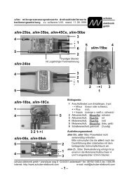
7 Connector systems and mounting instructions<br />
7.1 3.5 mm gold-contact connector system (pp35); max. load > 80A<br />
schulze<br />
elektronik<br />
gmbh<br />
page 7<br />
+ red plug wide sleeve narrow socket + red ( akku)<br />
Battery <strong>mcc</strong>-<strong>eagle</strong><br />
- black socket narrow sleeve wide plug - black ( akku)<br />
Caution: remove locating lug from battery cable. Do not remove lug from any cables attached to <strong>controller</strong>s or charge leads!<br />
Fit the connectors in the order shown above; the contacts are pressed in as follows:<br />
a. Place plastic sleeve vertically on table, grip end up. b. Push contact down into sleeve. c. Place 2.5mm wide screwdriver<br />
blade on top of cable solder joint inside sleeve. d. Tap screwdriver to press contact into sleeve until latch engages.<br />
7.2 4 mm gold-contact connector system (CT 4); max. load > 80A<br />
+ red sleeve wide plug socket sleeve narrow red ( akku)<br />
Battery <strong>mcc</strong>-<strong>eagle</strong><br />
- black sleeve narrow socket plug sleeve wide black ( akku)<br />
Fit the connectors in the order shown above; the contacts are pressed in as follows:<br />
a. Rest plastic sleeve on vice jaws with cables hanging down. b. Close vice jaws until cables are just free to move.<br />
c. Fit plug into socket and tap into sleeve until latch engages. d. Fit socket onto plug and tap into sleeve until latch engages.<br />
7.3 MPX gold-contact connector system (green or red); max. load approx. 30A<br />
+ red heat-shrink socket plug heat-shrink + red ( akku)<br />
Battery <strong>mcc</strong>-<strong>eagle</strong><br />
- black heat-shrink socket plug heat-shrink - red ( akku)<br />
Fit the connectors in the order shown above; the contacts are soldered as follows:<br />
a. To center the contacts fit plug and socket together be<strong>for</strong>e soldering. b. Tin all 6 exposed contacts of plug or socket.<br />
c. Fit cable end into triangle of contacts, solder to all three contacts. d. Position heat-shrink sleeve and shrink over joint.<br />
Installing the <strong>controller</strong> in the chassis:<br />
The ideal method of installing the unit is to attach it to the floor of the cradle or the rear of the chassis using<br />
Velcro (hook-and-loop) tape. Avoid any method which could produce a heat build-up in the <strong>eagle</strong>, and in<br />
particular never wrap it completely in foam rubber. Chapter 2 includes more in<strong>for</strong>mation on locating the<br />
<strong>controller</strong> in the model.<br />
Length of connecting cables:<br />
The cables to the drive battery and - in particular - to the motor should be kept as short as possible. Long<br />
cables act as aerials and can radiate interference; they also add unnecessary weight. See also Chapter 2.<br />
Motor connections:<br />
Solder short cables to the motor terminals (red to the positive terminal, black to negative). Solder these cables<br />
to the schulze perfect plug 35 plug (pp35-st), either ”in-line” or at right-angles, as best suits your installation.<br />
- insert the blue motor cable aligned with the blue mark (marker on the side of the black battery wire)<br />
- insert the red motor cable aligned with the red mark (marker on the side of the red battery wire)<br />
You may be able to arrange the cables so that they are not under tension, but if not, wrap fabric-based<br />
adhesive tape round the motor plug <strong>for</strong> safety’s sake.<br />
schulze elektronik gmbh • prenzlauer weg 6 • D-64331 weiterstadt • tel: 06150/1306-5, fax: 1306-99<br />
internet: http://www.schulze-elektronik.com e-mail: mail@schulze-elektronik.com
page 8<br />
Connecting the <strong>controller</strong> to the receiver:<br />
Locate the receiver cable attached to the <strong>mcc</strong><strong>eagle</strong><br />
and connect it to the throttle channel on<br />
the receiver, which is usually channel 2. The<br />
receiver’s operating voltage is fed to it through<br />
this channel, and the receiver uses it in turn to<br />
send control signals to the <strong>mcc</strong>-<strong>eagle</strong>. It is important<br />
to check regularly that the receiver and<br />
switch harness are securely connected to the<br />
<strong>eagle</strong>.<br />
Note: the colour coding of Futaba/Novak/<br />
Graupner (JR) receiver cables is correct, i.e.<br />
orange (signal) / red (+) / brown (-), but this<br />
may not apply to other receivers. Many mini-receivers<br />
<strong>for</strong> model car use have their own 5 V<br />
BEC system (you will see the letters BEC on<br />
the receiver label). If you connect this type of<br />
BEC receiver to the <strong>mcc</strong>-<strong>eagle</strong> you will often<br />
encounter problems, as the receiver cannot<br />
cope with the 5.7 V supply which it is fed - so to<br />
speak, backwards - via the servo cable. In this<br />
case you have two options:<br />
- set the BEC voltage of the <strong>mcc</strong>-<strong>eagle</strong> to the<br />
lower value (4.5 V). Un<strong>for</strong>tunately this also means<br />
that a steering servo connected to the receiver<br />
works on the same voltage. Alternatively:<br />
- cut through the positive wire in the 3-core receiver<br />
cable (centre wire, red), or remove the<br />
positive pin contact from the connector, and instead<br />
connect the 7.2 V FET servo current supply<br />
from the <strong>mcc</strong>-<strong>eagle</strong> to the + connection of<br />
the BEC receiver’s battery socket.<br />
- In many cases wiring a 1000 uF/10 V capacitor<br />
in parallel with the receiver voltage helps the<br />
situation. Check the polarity of the capacitor,<br />
solder it to a short piece of servo cable and<br />
plug it into any vacant receiver channel.<br />
- On no account connect a separate receiver<br />
battery to your receiver.<br />
Caution: the 7.2 V FET servo connection is not<br />
affected by the On/Off switch. If you want to<br />
isolate a BEC receiver from the power supply<br />
completely, you must disconnect the battery.<br />
FET servo:<br />
Attach the socket supplied with the servo to the<br />
blue 7.2 V cable attached to the FET servo, and<br />
simply connect it to the single pin below the<br />
switch socket. Secure it so that it cannot shake<br />
<strong>mcc</strong>-<strong>eagle</strong>: <strong>professional</strong> <strong>speed</strong> <strong>controller</strong> <strong>for</strong> <strong>rc</strong>-<strong>cars</strong><br />
itself loose. Please do not <strong>for</strong>get to solder the<br />
choke (supplied) in the cable.<br />
On/Off switch:<br />
If you want to install a switch you have to cut<br />
through the wire link adjacent to the three receiver<br />
cable sockets and solder the switch in that<br />
wire.<br />
Alternatively we can supply an optional prewired<br />
switch which can be clipped to both terminals<br />
after carefully removing the wire link.<br />
General note: the On/Off switch turns off the receiver<br />
and places the micro-processor in<br />
“stand-by” mode (red LED flashes at approx. 1<br />
x per second). It does not switch off the FET<br />
servo output! If a BEC receiver is connected at<br />
that point, the only way to remove power from it<br />
is to disconnect the drive battery.<br />
Connecting the command button:<br />
You only need to connect the command button<br />
(or the “tast-vm” - combined button / voltmeter)<br />
if you intend making changes to the properties<br />
of the unit (see Chapter 9).<br />
The push-button supplied (or the “tast-vm”)<br />
should be connected to the 3-pin socket below<br />
the servo cable.<br />
If you wish to use the functions of the ”tast-vm”<br />
it is important to connect its cable according to<br />
the colour coding of the 3-pin connector (see<br />
label on <strong>controller</strong>). The colour coding is not the<br />
same as that of the receiver cable.<br />
The configuration input is deliberately in a “concealed”<br />
position to avoid the risk of short-ci<strong>rc</strong>uits.<br />
If you need to change the configuration<br />
regularly we suggest that you either mount the<br />
<strong>eagle</strong> on Velcro (hook-and-loop) tape so that it<br />
is easy to remove, or permanently connect a<br />
short servo extension lead to the configuration<br />
input.<br />
Schottky diode:<br />
It is not normally necessary to solder a Schottky<br />
diode across the motor terminals, as the <strong>mcc</strong><strong>eagle</strong><br />
is fitted with internal diodes as standard.<br />
Brake light:<br />
See Chapter 11 <strong>for</strong> connections.<br />
schulze elektronik gmbh • prenzlauer weg 6 • D-64331 weiterstadt • tel: 06150/1306-5, fax: 1306-99<br />
internet: http://www.schulze-elektronik.com e-mail: mail@schulze-elektronik.com
<strong>mcc</strong>-<strong>eagle</strong>: <strong>professional</strong> <strong>speed</strong> <strong>controller</strong> <strong>for</strong> <strong>rc</strong>-<strong>cars</strong><br />
preliminary operating instructions <strong>for</strong> software V11, date of issue 11 APR 2000<br />
8 Variable properties,<br />
default settings<br />
The <strong>mcc</strong>-<strong>eagle</strong> is a multi-purpose <strong>speed</strong> <strong>controller</strong>.<br />
It is possible to alter certain of its properties by a configuration<br />
process to optimize it <strong>for</strong> use as a normal<br />
<strong>speed</strong> <strong>controller</strong>, a reversing <strong>speed</strong> <strong>controller</strong> or a<br />
<strong>speed</strong> governor (regulator).<br />
The <strong>mcc</strong>-<strong>eagle</strong> is configured at the factory in default<br />
mode; changing the operation mode is done by<br />
changing the unit's configuration. The table shows<br />
the features of the <strong>mcc</strong>-<strong>eagle</strong> which can be altered;<br />
note that the factory default values are underlined.<br />
If you have configured the <strong>mcc</strong>-<strong>eagle</strong> to suit a certain<br />
model and want to change to a different model<br />
at a later date (and in the meantime you may have<br />
<strong>for</strong>gotten the exact configuration of the <strong>mcc</strong>-<strong>eagle</strong>)<br />
than you can easily per<strong>for</strong>m a “general reset” which<br />
returns the <strong>mcc</strong>-<strong>eagle</strong> to the factory default settings.<br />
You can configure the <strong>mcc</strong>-<strong>eagle</strong> using -<br />
- the transmitter throttle stick and the external<br />
command button supplied with the <strong>controller</strong>.<br />
- the throttle stick and the external button/voltmeter<br />
combination (“tast-vm”, optional)<br />
- a PC, using the schulze-software “flysoft” and a<br />
suitable adapter cable “prog-adapt” (all optional).<br />
The cable attached to the push-button or the cable<br />
of the button/voltmeter can be connected directly to<br />
the <strong>mcc</strong>-<strong>eagle</strong> (observe polarity = color codes). Alternatively,<br />
the PC adapter cable can be connected<br />
directly to the <strong>mcc</strong>-<strong>eagle</strong> (and to the receiver).<br />
Parameters are configured in groups, and these are<br />
marked by thick outlines in the table.<br />
Note:<br />
Chapter 9 includes more details about changing the<br />
configuration of the <strong>mcc</strong>-<strong>eagle</strong>.<br />
If you accidentally store an incorrect value in the<br />
<strong>mcc</strong>-<strong>eagle</strong>, you can abandon the entry by setting it<br />
to “full brake” (throttle stick at minimum) then pressing<br />
the button several times until the unit returns to<br />
the “awaiting command” state. This procedure takes<br />
care that all other values following the incorrect, are<br />
not changed. You can now try again.<br />
Note: you can achieve the same result by disconnecting<br />
the <strong>mcc</strong>-<strong>eagle</strong> from the battery.<br />
Parameter Note<br />
Brake position (BP)<br />
Neutral position (NP)<br />
Full throttle posit. (FP)<br />
Start current<br />
Throttle acceleration,<br />
Soft start<br />
(s = seconds,<br />
ms = milliseconds<br />
ms = 1/1000 s)<br />
Continous current<br />
Minimum throttle<br />
min. braking effect<br />
max. braking effect<br />
schulze<br />
elektronik<br />
gmbh<br />
BP and NP<br />
can be identical.<br />
If BP<br />
between NP<br />
and FP: brakedeactivated!<br />
adjustable: 1.5s<br />
1.2s, 1s, 900,<br />
800, 700, 600,<br />
500, 400, 300,<br />
200, 100, 50,<br />
30, 10 ms<br />
0=special funct.<br />
0%...50% power<br />
page 9<br />
0,
page 10<br />
9 Altering the properties<br />
(configuration process)<br />
9.1 Symbols and terminology<br />
Configuration:<br />
Changing parameter settings to suit<br />
your application.<br />
Stick:<br />
The throttle stick on the transmitter.<br />
Any brake position: stick pointing towards<br />
you;<br />
0% = minimum value = usually neutral<br />
position of stick (stick released)<br />
100% = maximum value, stick usually<br />
pointing away from you.<br />
Brake position (abbreviation: BP):<br />
Gashebelposition, die den Motor zum<br />
Stillstand bringt<br />
Idle Position:<br />
Neutral position of stick:<br />
(abbreviation: NP)<br />
Position where the motor just barely<br />
runs<br />
Full-throttle position (abbrev.: FP):<br />
100% voltage passed to the motor<br />
Throttle position:<br />
The stick position is defined as<br />
1...100% throttle.<br />
Symbol also used to select an application.<br />
<strong>mcc</strong>-<strong>eagle</strong>: <strong>professional</strong> <strong>speed</strong> <strong>controller</strong> <strong>for</strong> <strong>rc</strong>-<strong>cars</strong><br />
LED-indicators:<br />
LED full on<br />
LED full off<br />
LED flashing at low rate<br />
LED flashing at high rate<br />
Using the push-button:<br />
Hold button pressed in<br />
(<strong>for</strong> specified duration)<br />
Release button<br />
Push button down and<br />
release immediately<br />
schulze elektronik gmbh • prenzlauer weg 6 • D-64331 weiterstadt • tel: 06150/1306-5, fax: 1306-99<br />
internet: http://www.schulze-elektronik.com e-mail: mail@schulze-elektronik.com<br />
Wait<br />
Audible indicator:<br />
This indicator is only audible when a<br />
motor is attached, as the motor itself<br />
acts as the loudspeaker.<br />
Single or multiple beep.<br />
1 beep represents a 10 A current value<br />
or 10% throttle stick position.<br />
Neutral = 0A = long beep;<br />
At tables: 1x beep per table value<br />
e
<strong>mcc</strong>-<strong>eagle</strong>: <strong>professional</strong> <strong>speed</strong> <strong>controller</strong> <strong>for</strong> <strong>rc</strong>-<strong>cars</strong><br />
preliminary operating instructions <strong>for</strong> software V11, date of issue 11 APR 2000<br />
You can alter the settings of the <strong>mcc</strong>-<strong>eagle</strong> in<br />
two ways: please see chapters 9.2 (standard<br />
configuration) and 9.3 (application configuration):<br />
Standard configuration process and general<br />
reset:<br />
1. Switch transmitter “On”<br />
2. Switch at <strong>mcc</strong>-<strong>eagle</strong> must be “Off”,<br />
battery pack disconnected.<br />
3. LEDs<br />
red green Note: hold push-button pressed in!<br />
4. Fahrakku anstecken<br />
e, LEDs<br />
red green<br />
Remarks:<br />
Re. 5.: The general reset is confirmed by both LEDs by<br />
switching off <strong>for</strong> one moment.<br />
Re.: 7. and 8.:<br />
Brake and neutral positions can be identical (identical<br />
positions must also be programmed two times)<br />
Brake position between idle position and full-throttle:<br />
Brake deactivated!<br />
LEDs<br />
LEDs<br />
red green select red greenselect<br />
red green select<br />
e<br />
7. Brake position<br />
LEDs<br />
Configured stick positions valid<br />
red<br />
green<br />
or<br />
5.<br />
wait <strong>for</strong> 2 to 20 seconds<br />
wait more than 30<br />
seconds to per<strong>for</strong>m<br />
general reset<br />
Neutral<br />
8. Idle position 9. Full-throttle posn.<br />
10. “ready <strong>for</strong> arming”<br />
Brake<br />
wait<br />
red<br />
green<br />
11. scharf<br />
red<br />
green<br />
LEDs flash alternately at high rate<br />
<strong>mcc</strong>-<strong>eagle</strong> is “armed”, that means “ready <strong>for</strong> use”<br />
e<br />
2 seconds<br />
wait<br />
2 seconds<br />
red egreen<br />
short<br />
e<br />
e<br />
6.<br />
e<br />
Property configuration process:<br />
1. Switch transmitter “On”<br />
2. Set throttle stick to “motor on”<br />
position, not to neutral or brake!<br />
3. Switch at <strong>mcc</strong>-<strong>eagle</strong> must be “Off”,<br />
battery pack disconnected.<br />
4. Connect battery pack<br />
5. Red and green LEDs flash<br />
alternately at low rate.<br />
6. Hold push-button pressed in<br />
continously <strong>for</strong> 3-15 seconds to<br />
change desired characteristic:<br />
schulze<br />
elektronik<br />
gmbh<br />
page 11<br />
9.2 Standard configuration:<br />
a. Resets the <strong>mcc</strong>-<strong>eagle</strong> to factory defaults (“general<br />
reset”), which is useful if you become confused<br />
at some stage in the programming sequence.<br />
See the table in Chapter 6.<br />
b. Program the stick positions <strong>for</strong> brake, idle and<br />
maximum rpm. Caution: If you only wish to per<strong>for</strong>m<br />
a “general reset” you must disconnect power<br />
from the <strong>mcc</strong>-<strong>eagle</strong> when both lights switches<br />
off <strong>for</strong> a moment.<br />
Note: A “general reset” causes the stick settings to<br />
Graupner mc-756 transmitter (brake, neutral<br />
and full-throttle positions) and all other settings<br />
(continous current, brake effekt, soft-start...) to<br />
revert to the factory defaults (see Section 7, underlined<br />
values).<br />
9.3 Property configuration:<br />
Once you have programmed stick positions in the<br />
standard configuration process, you can set the <strong>controller</strong><br />
to e.g. a predefined setup <strong>for</strong> raceways with<br />
less grip: setup # 1 (see diagram on next page).<br />
The following instructions show you how to start the<br />
sequence <strong>for</strong> selecting a desired application:<br />
LEDs<br />
green<br />
schulze elektronik gmbh • prenzlauer weg 6 • D-64331 weiterstadt • tel: 06150/1306-5, fax: 1306-99<br />
internet: http://www.schulze-elektronik.com e-mail: mail@schulze-elektronik.com<br />
red<br />
e
schulze elektronik gmbh • prenzlauer weg 6 • D-64331 weiterstadt • tel: 06150/1306-5, fax: 1306-99<br />
internet: http://www.schulze-elektronik.com e-mail: mail@schulze-elektronik.com<br />
3s<br />
e<br />
6s<br />
e<br />
9s<br />
e<br />
12s<br />
e<br />
15s<br />
e<br />
Open the throttle slightly to ensure that you enter the property configuration procedure.<br />
Note: the LED indicators shown below only apply when the throttle stick is in the “motor on” range. The red and green LEDs glow to indicate the neutral position.<br />
LEDs<br />
red green<br />
red green<br />
red green<br />
red green<br />
red green<br />
LEDs<br />
red<br />
red<br />
red<br />
green<br />
green<br />
green<br />
start current<br />
stick position<br />
actual<br />
value<br />
actual<br />
value<br />
18 ... 180A<br />
0% ... 50%<br />
of<br />
batteryvoltage<br />
stick position<br />
here: nothing<br />
important.<br />
<strong>mcc</strong>-<strong>eagle</strong><br />
gives 0.5V:<br />
“tast-vm” shows<br />
1/2 deflection<br />
select<br />
select<br />
e<br />
calibration of "tast-vm"<br />
LEDs<br />
red<br />
red<br />
green<br />
red green<br />
select<br />
red green<br />
Br, 0, 10...100%<br />
turbo start<br />
minimum-throttle (motor voltage)<br />
ready<br />
1.5s...10ms<br />
Br, 0, 10-100%<br />
see<br />
table of<br />
timevalues<br />
accelleration time<br />
green<br />
red green Br, 25,50,75,100% select red green<br />
or<br />
ABS<br />
ready<br />
red green<br />
actual<br />
value<br />
minimum brake effect<br />
actual<br />
value<br />
BEC voltage<br />
LEDs<br />
select red green<br />
select<br />
Br, 0 ...100%<br />
actual<br />
value<br />
LEDs<br />
red green<br />
select red green select red green<br />
select<br />
red<br />
ready<br />
actual<br />
value<br />
0A ... 100A<br />
see<br />
table of<br />
current<br />
values<br />
continous current<br />
maximum brake effect<br />
green<br />
e<br />
e<br />
hold red green 3sec red green then or red green then or red green<br />
3sec 3sec<br />
press in,<br />
spec see<br />
actual ial table of<br />
value func- current<br />
tion<br />
values<br />
e<br />
Br, 0, 10-100%<br />
off<br />
1-10s<br />
activationtime<br />
stick position<br />
Br, 0%...100%<br />
stick position<br />
actual<br />
value<br />
Type1<br />
Type2<br />
Type3<br />
off<br />
choose setup<br />
e<br />
e<br />
e<br />
e<br />
kurz<br />
setup # 1<br />
actual<br />
value<br />
spec<br />
ial<br />
function<br />
stick position<br />
Br, 0%...100%<br />
0%...100%<br />
brakeeffect<br />
stick position<br />
Br,0%, 50%, 100%<br />
4.5V 5.7V<br />
e<br />
setup # 2<br />
stick position<br />
Br, 0%...100%<br />
0%...100%<br />
brakeeffect<br />
setup # 3<br />
e<br />
ready<br />
Legend LED on LED blinks<br />
LED flickers LED off<br />
e<br />
e<br />
ready<br />
Legend: The underlined values are the predefined<br />
values after a “general reset”<br />
actual value= old, actual valid value<br />
Br. = brake position, e = beep of the motor<br />
e<br />
e<br />
then or<br />
3sec<br />
Propertyconfiguration<br />
table 9.3<br />
e<br />
red green<br />
no change<br />
Configuration finished:<br />
“ready”.<br />
A Activation<br />
1. Choose neutral or<br />
brake position.<br />
2. Auto-arm:<br />
Wait <strong>for</strong> 2 seconds.<br />
3. <strong>mcc</strong>-<strong>eagle</strong> is armed<br />
(ready to use).<br />
In neutral position:<br />
red LED and green<br />
LED flash at high<br />
rate.<br />
In brake position:<br />
red LED blinks and<br />
green LED off.<br />
OR<br />
B Continuing configuration<br />
1. Choose throttle position<br />
2. Push button <strong>for</strong> 3, 6,<br />
9, 12 or 15seconds.<br />
Continue configuration<br />
with right second<br />
value<br />
red<br />
ready<br />
green<br />
page 12<br />
<strong>mcc</strong>-<strong>eagle</strong>: <strong>professional</strong> <strong>speed</strong> <strong>controller</strong> <strong>for</strong> <strong>rc</strong>-<strong>cars</strong>
schulze elektronik gmbh • prenzlauer weg 6 • D-64331 weiterstadt • tel: 06150/1306-5, fax: 1306-99<br />
internet: http://www.schulze-elektronik.com e-mail: mail@schulze-elektronik.com<br />
9.3.1 Explanatory notes on adjusting the characteristics of the <strong>mcc</strong>-<strong>eagle</strong><br />
- When the red and green LEDs are flashing slowly and alternately, the <strong>controller</strong>’s status is ”awaiting command”. In this mode you can select any of several parameters<br />
and alter them. This is done by holding the button pressed in (the command button or ”tast-vm” must be connected).<br />
- If the transmitter throttle stick is at the brake position, the ”tast-vm” always shows the currently set value, and the <strong>controller</strong> then accepts this value if you simply<br />
press the button (especially if you decide not to alter a parameter value). You will also hear 1 ... 10 beeps from the motor in the brake position if the throttle stick<br />
was briefly in the ”motor-on” range previously. While the unit is beeping the ”tast-vm” or any other voltmeter connected to the system shows nothing.<br />
- You can set any of the following 16 current values <strong>for</strong> ”start-up current” and ”continuous current” (1st / 3rd configuration values after holding the button pressed in <strong>for</strong> 3 sec.)<br />
Throttle stick position 0 10 20 30 40 50 60 70 80 90 100% throttle; 100% throttle switches off the soft start function!<br />
Start-up current 0 20 40 60 80 100 120 140 160 180 200A; Note: All current values of <strong>eagle</strong>3 1.5 times higher!<br />
Continous current 0 10 20 30 40 50 60 70 80 90 100A Note: All current values of <strong>eagle</strong>3 1.5 times higher!<br />
- You can set any of the following 15 soft-start time values <strong>for</strong> “acceleration time” (2nd configuration value after holding button pressed in <strong>for</strong> 3 seconds):<br />
0 5 25 50 75 100% throttle<br />
xx. 1.5 s 1.25 s 1 s 900 800 700 600 500 400 300 200 100 50 30 10 ms, xx = no time value, special function<br />
- Turbo start (button pressed in <strong>for</strong> 6 seconds):<br />
The <strong>mcc</strong>-<strong>eagle</strong> activates the turbo function if it is left in the brake position <strong>for</strong> the period of the ”activation time”. While the turbo-start function is active the control range from stop<br />
to full throttle is reduced to one third of the throttle stick travel, i.e. the full-throttle position is reached much earlier, but the proportional throttle function is still maintained (i.e. it is<br />
not a switched function). This means that it is still possible to drive your car slowly with the turbo function active. The turbo function is switched off automatically when the throttle<br />
stick is first moved back towards idle (neutral) by about 5% after the initial acceleration phase, i.e. the first time you reduce throttle again.<br />
- Minimum throttle (1st configuration value, button pressed in <strong>for</strong> 9 seconds)<br />
In some situations it can be useful to set a particular throttle position below which the signal never falls. The result is that the motor immediately starts up at a raised<br />
throttle value when you advance the transmitter stick. The effect is that the control range between the idle and full-throttle positions operates at even higher<br />
resolution (note: the limiters are still active).<br />
- Minimum braking effect (2nd configuration value, button pressed in <strong>for</strong> 9 seconds):<br />
In some cases it can be useful to set up a non-linear braking effect. For example, if you wish to implement gentle automatic braking be<strong>for</strong>e entering a turn, you<br />
should raise the minimum braking effect (e.g. to 15%) and then move the throttle trim on your transmitter to the ”brake” area when driving. The car will then brake<br />
automatically at your selected rate (15% in this case) when you move the throttle stick to neutral.<br />
- Maximum braking effect (3rd configuration value, button pressed in <strong>for</strong> 9 seconds):<br />
On tracks where grip (adhesion) is relatively poor, you can avoid the danger of skidding, even under full brake, by limiting the available braking power.<br />
- ABS (1st configuration value, button pressed in <strong>for</strong> 12 seconds):<br />
The <strong>mcc</strong>-<strong>eagle</strong> includes a function which works in a similar way to ABS. Since the <strong>mcc</strong>-<strong>eagle</strong> cannot rely on in<strong>for</strong>mation from wheel sensors, it releases the brake<br />
briefly when the motor stops turning. The released brake allow the wheels to continue to rotate, and the car will regain traction provided that track adhesion is<br />
sufficient to re-accelerate the locked wheel. There are three variations on this feature.<br />
- BEC voltage (2nd configuration value, button pressed in <strong>for</strong> 12 seconds):<br />
If minimum soft-start is selected, the <strong>mcc</strong>-<strong>eagle</strong> immediately passes full battery voltage to the motor. In this situation the high start-up current can cause the operating<br />
voltage to collapse momentarily to less than 3.5 V. The stabilised BEC voltage of 5.7 V then collapses in turn. Many receivers respond to this event by emitting false<br />
control signals which produce unwanted steering movements and uneven throttling. At the 4.5 V position the receiver does not ”see” voltage dips in the drive battery<br />
down to 4.5 V, and it does not produce the spurious signals. Drawback: a normal servo operates too slowly at this voltage. Solution: use an FET servo.<br />
- ”tast-vm” calibration and set-up (configuration values, button pressed in <strong>for</strong> 15 seconds)<br />
1. This function allows you to check the calibration of a ”tast-vm” or a digital voltmeter, so that you can be reasonably confident of the indicated current values.<br />
2. The <strong>mcc</strong>-<strong>eagle</strong> contains three standard set-ups <strong>for</strong> tracks of different type and varying grip (adhesion). There is also a fourth set-up - the ”hottest” one - which is obtained by carrying out a<br />
”general reset”, but this procedure does alter the throttle stick settings. Of course, these set-ups can also be fine-tuned, i.e. used as the basis <strong>for</strong> further optimisation.<br />
Start-up current Accelereation Contin. current Min. throttle Min.brake Max.brake Note:<br />
Set-up # 1 12A 500ms 27A 10% 10% 75% All current values of <strong>eagle</strong>3 1.5 times higher!<br />
Set-up # 2 17A 250ms 37A 20% 20% 85% All current values of <strong>eagle</strong>3 1.5 times higher!<br />
Set-up # 3 21A 100ms 50A 20% 20% 95% All current values of <strong>eagle</strong>3 1.5 times higher!<br />
page 13<br />
elektronik<br />
gmbh<br />
<strong>mcc</strong>-<strong>eagle</strong>: <strong>professional</strong> <strong>speed</strong> <strong>controller</strong> <strong>for</strong> <strong>rc</strong>-<strong>cars</strong><br />
preliminary operating instructions <strong>for</strong> software V11, date of issue 11 APR 2000<br />
schulze
page 14<br />
9.3.2 Explanatory notes on setting<br />
the torque limiters<br />
It is possible to alter the acceleration characteristics<br />
of the <strong>mcc</strong>-<strong>eagle</strong>, e.g. <strong>for</strong> competition<br />
use. If you don’t have the ”golden thumbs” of<br />
the expert driver, you can set up the <strong>mcc</strong>-<strong>eagle</strong><br />
to suit a particular track very accurately<br />
just by changing three parameters.<br />
For example, you can use this facility to avoid<br />
the motor drawing such a high start-up current<br />
that the drive battery is discharged prematurely.<br />
You can avoid the wheels spinning by limiting<br />
motor current.<br />
You can achieve the same effect by altering the<br />
acceleration characteristics (soft-start) of the<br />
vehicle.<br />
The difference between the two methods is that<br />
reducing maximum permissible motor current<br />
<strong>for</strong> the acceleration phase may also limit<br />
the maximum <strong>speed</strong> of the model, whereas<br />
altering the soft-start characteristics only<br />
causes motor voltage to be increased more or<br />
less quickly, and this has no effect on the<br />
model’s absolute maximum <strong>speed</strong>.<br />
Altering the soft-start characteristics has a<br />
useful side-benefit in that it results in a slightly<br />
exponential curve as current rises (good <strong>for</strong><br />
acceleration out of a turn).<br />
The <strong>mcc</strong>-<strong>eagle</strong> features three configurable limiters<br />
which influence the car’s running characteristics:<br />
start-up current value, acceleration value<br />
(soft-start) and continuous current value.<br />
Adjusting and setting up all the possible variations<br />
can be a very complex procedure, and to<br />
make matters easier we have provided special<br />
configurations which are much easier to<br />
understand: single current limiting and<br />
double current limiting.<br />
Single current limiting corresponds to the current<br />
limiting process possible with <strong>speed</strong> <strong>controller</strong>s<br />
which are not micro-processor controlled.<br />
The three standard set-ups can also be used as<br />
the basis <strong>for</strong> your own adaptation, so that you<br />
can gradually feel your way towards the exact<br />
handling characteristics you prefer.<br />
<strong>mcc</strong>-<strong>eagle</strong>: <strong>professional</strong> <strong>speed</strong> <strong>controller</strong> <strong>for</strong> <strong>rc</strong>-<strong>cars</strong><br />
9.3.2.1 Single current limiting<br />
(beginner’s configuration)<br />
Only one current value is to be selected.<br />
Single current limiting is the process by which<br />
you configure the maximum possible current<br />
which the <strong>mcc</strong>-<strong>eagle</strong> passes to your motor under<br />
any ci<strong>rc</strong>umstances. This current value is<br />
never exceeded, neither at the start of a race<br />
nor during normal driving.<br />
The process represents the simplest <strong>for</strong>m of<br />
motor torque limiting.<br />
Single current limiting is set using the 3-second<br />
(3s) configuration process shown in the sequential<br />
chart on page 12. As you can see<br />
from the diagram, there are three configuration<br />
steps <strong>for</strong> the 3s configuration process, although<br />
in this case we only require one current<br />
value. This just means that the current limiting<br />
value is defined as the continuous current<br />
configuration (the 3rd configuration step), and<br />
steps 1 and 2 are skipped. This is done by defining<br />
them as 0%.<br />
The procedure corresponds to defining<br />
”idle”, ”idle”, and ”desired current value”.<br />
Check that both LEDs on the <strong>mcc</strong>-<strong>eagle</strong> are<br />
glowing when you enter ”idle”, otherwise it will<br />
not adopt the single current limiting mode.<br />
Note: if you define the limited current as 100%,<br />
you will obtain the fastest possible acceleration,<br />
and the soft-start feature will be disabled.<br />
Caution: there is a ”catch” to this set-up: if you<br />
have a powerful motor and battery voltage is<br />
falling off, when you abruptly apply full throttle<br />
the vehicle may only jerk. This is the result of<br />
battery voltage collapsing instantaneously below<br />
the minimum permissible value.<br />
Current<br />
Graph of configured maximum permissible motor<br />
current over time<br />
1 sec Time<br />
schulze elektronik gmbh • prenzlauer weg 6 • D-64331 weiterstadt • tel: 06150/1306-5, fax: 1306-99<br />
internet: http://www.schulze-elektronik.com e-mail: mail@schulze-elektronik.com
<strong>mcc</strong>-<strong>eagle</strong>: <strong>professional</strong> <strong>speed</strong> <strong>controller</strong> <strong>for</strong> <strong>rc</strong>-<strong>cars</strong><br />
preliminary operating instructions <strong>for</strong> software V11, date of issue 11 APR 2000<br />
9.3.2.2 Double current limiting<br />
(advanced configuration)<br />
Two current values are to be selected:<br />
start-up current and continuous current.<br />
The start-up current is not exceeded when the<br />
vehicle is in the acceleration phase.<br />
The continuous current is not exceeded during<br />
normal driving, but the limit is only applied<br />
one second after the vehicle has completed<br />
any acceleration phase.<br />
Double current limiting is set in the 3-second<br />
(3s) configuration process, as shown in the<br />
sequential chart on page 12. As you can see<br />
from the diagram, there are three configuration<br />
steps <strong>for</strong> the 3s configuration process, although<br />
in this case we only require two current<br />
values. This means that the current limiter values<br />
are defined as the start-up current and<br />
the continuous current, and step 2 is skipped.<br />
This is done by defining it as 0%.<br />
This procedure corresponds to defining “startup<br />
current”,“idle”, and “continuous current”.<br />
Check that both LEDs on the <strong>mcc</strong>-<strong>eagle</strong> are<br />
glowing when you enter “idle”, otherwise it will<br />
not adopt the double current limiting mode.<br />
Note also that the start-up current must not be<br />
defined as the idle position of the throttle<br />
stick, as this would activate single current limiting.<br />
Definition of acceleration: the <strong>mcc</strong>-<strong>eagle</strong><br />
considers that acceleration occurs only if the<br />
throttle stick is at least briefly in the neutral<br />
range be<strong>for</strong>e the throttle is opened.<br />
Note also: the start-up current value defined<br />
in the first stage of configuration gradually (within<br />
one second) rises or falls to the value<br />
which you have defined in the third stage of<br />
configuration (continuous current value). The<br />
result is a current curve which is time-limited.<br />
Note: if you define the start-up current or the<br />
continuous current as 100%, you will obtain<br />
the fastest possible acceleration, and the softstart<br />
feature will be disabled. Caution: there is<br />
a ”catch” to this set-up: if you have a powerful<br />
motor and battery voltage is falling off, when<br />
you abruptly apply full throttle the vehicle may<br />
only jerk.<br />
schulze<br />
elektronik<br />
gmbh<br />
page 15<br />
Effect of double current limiting:<br />
Example 1: the start-up current is programmed<br />
to a lower value than the continuous<br />
current:<br />
a) If the configured start-up current is lower<br />
than the start-up current required by the motor,<br />
the vehicle will accelerate gently.<br />
You can there<strong>for</strong>e set different acceleration values<br />
by varying the start-up current: with 10%<br />
start-up current (= greater than zero) the<br />
throttle stick accelerates the vehicle gradually;<br />
whereas increasing the start-up current immediately<br />
starts the motor running when you<br />
open the throttle.<br />
b1) If the configured continuous current is higher<br />
than the continuous current actually required<br />
by the motor, acceleration continues up to<br />
the maximum <strong>speed</strong> of the vehicle.<br />
b2) If the configured continuous current is lower<br />
than the continuous current actually required by<br />
the motor, the vehicle only runs at “half power”.<br />
Example 2: the start-up current is programmed<br />
to a higher value than the continuous<br />
current.<br />
a) If the configured start-up current is greater<br />
than the actual start-up current of the motor,<br />
the vehicle accelerates with full power.<br />
b1) If the configured continuous current is higher<br />
than the continuous current actually required<br />
by the motor, acceleration continues up to<br />
the vehicle’s maximum <strong>speed</strong>.<br />
b2) If the configured continuous current is lower<br />
than the continuous current actually required by<br />
the motor, the vehicle only runs at “half power”.<br />
Example 3: the start-up current is set to the<br />
same value as the continuous current.<br />
Special case: works like single current limiting<br />
described in Chapter 9.3.2.1.<br />
Current<br />
Start-up current<br />
Example 2<br />
Continuous<br />
current<br />
Example 1<br />
Start-up current<br />
Configured maximum permissible<br />
motor current over time<br />
schulze elektronik gmbh • prenzlauer weg 6 • D-64331 weiterstadt • tel: 06150/1306-5, fax: 1306-99<br />
internet: http://www.schulze-elektronik.com e-mail: mail@schulze-elektronik.com<br />
1 sec<br />
Time
page 16<br />
9.3.2.3 Triple current limiting<br />
Two current values (start-up current and<br />
continuous current) are to be selected,<br />
plus one acceleration value.<br />
What the three parameters mean, and how<br />
they work:<br />
1st parameter: start-up current<br />
- The start-up current value determines the<br />
point at which the soft-start limiter takes effect.<br />
- If the defined start-up current is exceeded, the<br />
soft-start limiter is activated.<br />
- If the start-up current value is not exceeded,<br />
the soft-start limiter is disabled.<br />
Purpose: the start-up current is adjusted so<br />
that, from a ”motor stopped” situation, the<br />
voltage (i.e. torque) fed to the motor is not<br />
sufficient to allow the wheels of the vehicle to<br />
spin.<br />
When set up perfectly, the rate of acceleration<br />
is dictated by the 2nd configuration value (acceleration)<br />
described below, as soon as the<br />
vehicle is moving. Note that the acceleration<br />
phase is purely time-related.<br />
Note: if the motor draws less than the programmed<br />
start-up current during the acceleration<br />
phase, the voltage to the motor is raised gently<br />
from zero up to maximum operating voltage<br />
in 10 ms (i.e. in one hundredth of a second).<br />
This produces a highly efficient rising torque<br />
curve. At the same time the process protects<br />
the motor magnets from damage, as current<br />
cannot rise instantaneously. To obtain fastest<br />
possible acceleration you should define the<br />
start-up current as 100%, as this by-passes<br />
the brief soft-start.<br />
2nd parameter: acceleration<br />
- The acceleration value defines the period over<br />
which the <strong>mcc</strong>-<strong>eagle</strong> may increase motor<br />
voltage from 0% to 100% (0 V to 7.2 V with a<br />
six-celled battery).<br />
- The higher the acceleration value, the faster<br />
the voltage to the motor rises.<br />
- The lower the acceleration value, the longer<br />
the soft-start period.<br />
<strong>mcc</strong>-<strong>eagle</strong>: <strong>professional</strong> <strong>speed</strong> <strong>controller</strong> <strong>for</strong> <strong>rc</strong>-<strong>cars</strong><br />
Purpose: the aim is to set an acceleration value<br />
which ensures that the vehicle’s wheels do<br />
not spin, i.e. the motor’s torque should be<br />
maintained at a virtually constant level. The<br />
torque level must be adjusted to suit the prevailing<br />
track conditions.<br />
- The acceleration value you set determines the<br />
torque and the subsequent increase in current<br />
of the motor (similar to a current rise<br />
function).<br />
Graduation: the scale of acceleration values<br />
relative to the throttle stick position which is<br />
used to define the value is not linear (see table<br />
9.3.1).<br />
Special case 0%: not permissible when the<br />
<strong>professional</strong> configuration option is used.<br />
Note: acceleration is purely time-related. If you<br />
wish to drive your car using a defined current<br />
limit <strong>for</strong> the acceleration phase, you must use<br />
double or single current limiting. Nevertheless,<br />
the acceleration phase is limited by a<br />
maximum current value, but this is not variable<br />
by the user; it is double the continuous<br />
current value, falling to the actual continuous<br />
current value within the first second.<br />
The set soft-start time refers to the period over<br />
which the soft-start rises from 0 to 100%<br />
throttle.<br />
If the acceleration value corresponds to a softstart<br />
time of, say, 1 sec., and the motor sees<br />
3.6 V (i.e. half battery voltage) at the time<br />
when the soft-start limiter trips (i.e. when the<br />
start-up current value is exceeded), then the<br />
time to reach full throttle is not a full second,<br />
but only 0.5 sec.<br />
By configuring the start-up current value and/<br />
or the acceleration current value carefully it<br />
is possible virtually to switch off the soft-start<br />
phase altogether, either by defining the startup<br />
current value as maximum start-up current,<br />
or the acceleration value to maximum acceleration<br />
(= minimum soft-start).<br />
schulze elektronik gmbh • prenzlauer weg 6 • D-64331 weiterstadt • tel: 06150/1306-5, fax: 1306-99<br />
internet: http://www.schulze-elektronik.com e-mail: mail@schulze-elektronik.com
<strong>mcc</strong>-<strong>eagle</strong>: <strong>professional</strong> <strong>speed</strong> <strong>controller</strong> <strong>for</strong> <strong>rc</strong>-<strong>cars</strong><br />
preliminary operating instructions <strong>for</strong> software V11, date of issue 11 APR 2000<br />
To re-iterate: by configuring the start-up current<br />
value to minimum start-up current the<br />
soft-start function takes effect virtually immediately.<br />
However, if you set the acceleration<br />
value close to maximum acceleration, the reduction<br />
in the start-up current value has no<br />
effect.<br />
In numerical terms: if you configure the acceleration<br />
value as 100% (minimum soft-start),<br />
motor voltage rises to the maximum value of<br />
drive battery voltage within 10 ms. However,<br />
this also means that a low start-up current value<br />
has no effect if the acceleration value is<br />
set to 100%.<br />
Current<br />
Start-up current value<br />
schulze<br />
elektronik<br />
gmbh<br />
page 17<br />
3rd parameter: continuous current value<br />
- The peak current of the time-related current<br />
limiting function is double the continuous<br />
current value.<br />
- The peak current value is reduced linearly to<br />
the continuous current value within a period<br />
of one second.<br />
- The falling curve of maximum permissible motor<br />
current may also limit the acceleration<br />
function in terms of current, even though it is<br />
normally purely time-related.<br />
- The longer the period of the soft-start, i.e. the<br />
gentler the acceleration, the less current is<br />
available <strong>for</strong> acceleration in terms of maximum<br />
permissible motor current - but at the<br />
same time gentler acceleration consumes<br />
less current.<br />
The graph printed below is intended to clarify<br />
the inter-connected nature of the functions<br />
described above.<br />
Peak current, (double the defined continuous current)<br />
(reducing over 1 sec. to the continuous current value)<br />
maximum permissible motor current<br />
0.5<br />
sec.<br />
1 second<br />
Motor 1; soft-start approx. 0.20 sec. (=200ms)<br />
Motor 2; soft-start approx. 0.35 sec. (=350ms)<br />
Continuous current value<br />
Motor 1; current values limited by<br />
programmed values at all points<br />
Motor 2; current values below all limits<br />
schulze elektronik gmbh • prenzlauer weg 6 • D-64331 weiterstadt • tel: 06150/1306-5, fax: 1306-99<br />
internet: http://www.schulze-elektronik.com e-mail: mail@schulze-elektronik.com<br />
Time
page 18<br />
10 Sample configurations<br />
Essential pre-condition:<br />
The <strong>mcc</strong>-<strong>eagle</strong> must be aware of your<br />
transmitter’s throttle stick travels, i.e. you<br />
must have carried out the standard configuration<br />
already.<br />
1st aim:<br />
To configure single current limiting to 20 A<br />
maximum current:<br />
a. Switch on transmitter and receiver.<br />
b. Set throttle stick to “motor on” position (i.e.<br />
not idle/brake; use trim as aid).<br />
c. Connect command button or “tast-vm” to the<br />
<strong>mcc</strong>-<strong>eagle</strong>;<br />
d. If an On/Off switch is connected to the <strong>mcc</strong><strong>eagle</strong>,<br />
set it to ON.<br />
e. Connect the <strong>mcc</strong>-<strong>eagle</strong> to the drive battery;<br />
- red and green LEDs flash slowly and alternately;<br />
- the <strong>mcc</strong>-<strong>eagle</strong> is in the “awaiting command”<br />
state;<br />
- it is not armed, as the throttle trim is not at<br />
neutral.<br />
f. Hold the command button pressed in <strong>for</strong> 3<br />
seconds:<br />
- after 3 secs. the red LED glows, the green<br />
LED goes out.<br />
g. Release button.<br />
- the red LED glows, the green LED flashes.<br />
- The <strong>mcc</strong>-<strong>eagle</strong> is in the correct mode <strong>for</strong><br />
setting the start-up current.<br />
h. For single current limiting the start-up current<br />
value must be defined as 0 A, so set the<br />
throttle stick to neutral. Check the neutral position<br />
of the two LEDs on the <strong>mcc</strong>-<strong>eagle</strong>:<br />
- both LEDs must be glowing.<br />
If this is not the case, correct the neutral setting<br />
with the help of the throttle trim.<br />
i. Press the button briefly.<br />
- the red LED goes out, the green LED<br />
glows;<br />
- the <strong>mcc</strong>-<strong>eagle</strong> is now in the correct<br />
mode <strong>for</strong> setting the acceleration value.<br />
j. For single current limiting the acceleration va-<br />
<strong>mcc</strong>-<strong>eagle</strong>: <strong>professional</strong> <strong>speed</strong> <strong>controller</strong> <strong>for</strong> <strong>rc</strong>-<strong>cars</strong><br />
lue must also be defined as the idle setting,<br />
so set the throttle stick to neutral.<br />
k. Press the button briefly.<br />
- the red LED flashes, the green LED goes<br />
out.<br />
- The <strong>mcc</strong>-<strong>eagle</strong> is now in the correct<br />
mode <strong>for</strong> setting the continuous current<br />
value.<br />
l. Set the throttle stick to about 20% throttle,<br />
i.e. around 1/5 of full throttle. The table in<br />
Chapter 9.3.1 shows that this corresponds to<br />
a current value of 20A.<br />
m. Press the button briefly.<br />
- the red and green LED flash slowly and alternately;<br />
- the <strong>mcc</strong>-<strong>eagle</strong> is again in the ”awaiting<br />
command” mode.<br />
Configuration concluded.<br />
Test:<br />
n. Set the throttle stick to idle and wait 2 sec.<br />
- The <strong>mcc</strong>-<strong>eagle</strong> is armed, the red and<br />
green LEDs flash fast and alternately.<br />
- If the throttle stick is at the brake position,<br />
the red LED flashes, the green LED goes<br />
out.<br />
o. Hold the model with the wheels clear and<br />
open the throttle quickly.<br />
- The motor should run up to <strong>speed</strong> gradually<br />
(soft-start), as the relatively low current limit<br />
value drastically restricts the start-up current,<br />
which would normally be very much<br />
higher.<br />
p. Throttle stick back to brake position.<br />
- The motor stops.<br />
Test concluded.<br />
2nd aim:<br />
To configure single current limiting to 60 A<br />
maximum current.<br />
The procedure is identical to that described under<br />
1. as far as point l.<br />
At point l. set the throttle stick to slightly more<br />
than half-throttle = 60% throttle = 60 A.<br />
In the test described in point o. the motor<br />
should now pick up <strong>speed</strong> quickly.<br />
schulze elektronik gmbh • prenzlauer weg 6 • D-64331 weiterstadt • tel: 06150/1306-5, fax: 1306-99<br />
internet: http://www.schulze-elektronik.com e-mail: mail@schulze-elektronik.com
<strong>mcc</strong>-<strong>eagle</strong>: <strong>professional</strong> <strong>speed</strong> <strong>controller</strong> <strong>for</strong> <strong>rc</strong>-<strong>cars</strong><br />
preliminary operating instructions <strong>for</strong> software V11, date of issue 11 APR 2000<br />
3rd aim:<br />
To configure minimum throttle (start-up<br />
throttle) to 25%:<br />
a. Switch on the transmitter and receiver;<br />
b. Set the throttle stick to a “motor on” position<br />
(not idle/brake; use trim as an aid).<br />
c. Connect command button or “tast-vm” to the<br />
<strong>mcc</strong>-<strong>eagle</strong>;<br />
d. If an On/Off switch is connected to the <strong>mcc</strong><strong>eagle</strong>,<br />
set it to ON.<br />
e. Connect the <strong>mcc</strong>-<strong>eagle</strong> to the drive battery;<br />
- red and green LEDs flash slowly and alternately;<br />
- the <strong>mcc</strong>-<strong>eagle</strong> is in the “awaiting command”<br />
state;<br />
- it is not armed.<br />
f. Hold the button pressed in <strong>for</strong> 9 seconds:<br />
- LEDs after 3 sec.: red on, green off;<br />
- LEDs after 6 sec.: red off, green on;<br />
- LEDs after 9 sec.: red flashes green off.<br />
g. Release button.<br />
- The red LED is on, the green LED is off.<br />
- The <strong>mcc</strong>-<strong>eagle</strong> is in the correct mode <strong>for</strong><br />
setting the minimum throttle value.<br />
h. The effective stick travel is expanded to help<br />
you set the minimum throttle value accurately.<br />
In accordance with the configuration chart<br />
(see Chapter 9.3) only 50% of the battery<br />
voltage is passed to the motor when the<br />
throttle stick is at the 100% position (100% =<br />
full throttle). This means: to set 25% minimum<br />
throttle you must set the throttle stick to<br />
50% throttle (half-throttle).<br />
i. Press the button briefly.<br />
- the red LED is off, the green LED is on;<br />
- the <strong>mcc</strong>-<strong>eagle</strong> is now in the correct<br />
mode <strong>for</strong> setting minimum brake effect.<br />
j. As we do not wish to make any changes<br />
here, move the throttle stick to a “brake” position<br />
in order to accept the old value. If the<br />
motor beeps, wait <strong>for</strong> the sound to stop be<strong>for</strong>e<br />
continuing with j.<br />
k. Press the button briefly.<br />
- the red LED flashes, the green LED glows;<br />
- the <strong>mcc</strong>-<strong>eagle</strong> is in the correct mode <strong>for</strong><br />
setting maximum brake effect.<br />
schulze<br />
elektronik<br />
gmbh<br />
page 19<br />
l. Once again we do not wish to make any<br />
change here, so set the throttle stick to, say,<br />
full brake in order to accept the previous value.<br />
If the motor beeps (repeatedly), wait until<br />
the sound stops be<strong>for</strong>e continuing with l.<br />
m. Press the button briefly.<br />
- the red and green LEDs flash slowly and<br />
alternately;<br />
- the <strong>mcc</strong>-<strong>eagle</strong> is again in the “awaiting<br />
command” state.<br />
Configuration concluded.<br />
Test:<br />
n. Set throttle stick to idle, wait 2 sec.<br />
- The <strong>mcc</strong>-<strong>eagle</strong> is armed, the red and<br />
green LEDs flash fast and alternately.<br />
- If the throttle stick is at the brake position<br />
instead, the red LED flashes, the green LED<br />
is off.<br />
o. Hold the model with the wheels clear and<br />
open the throttle very slightly.<br />
- The motor should not “soft-start”, because<br />
it is immediately fed 25% throttle. With a battery<br />
voltage of 8 V that is already 2 V! Since<br />
the limiters are still active, they may restrict<br />
this start-up process.<br />
p. Throttle stick to brake position.<br />
- The motor stops.<br />
Test concluded.<br />
4th aim:<br />
To set <strong>professional</strong> current limiting:<br />
Start-up current (20 A, see text below),<br />
acceleration 300 ms, continuous current<br />
50 A<br />
a. Switch on transmitter and receiver.<br />
b. Set throttle stick to “motor on” position (i.e.<br />
not idle/brake; use trim as aid).<br />
c. Connect command button or “tast-vm” to the<br />
<strong>mcc</strong>-<strong>eagle</strong>;<br />
d. If an On/Off switch is connected to the <strong>mcc</strong><strong>eagle</strong>,<br />
set it to ON.<br />
e. Connect the <strong>mcc</strong>-<strong>eagle</strong> to the drive battery;<br />
- red and green LEDs flash slowly and alternately;<br />
- the <strong>mcc</strong>-<strong>eagle</strong> is in the “awaiting command”<br />
state;<br />
schulze elektronik gmbh • prenzlauer weg 6 • D-64331 weiterstadt • tel: 06150/1306-5, fax: 1306-99<br />
internet: http://www.schulze-elektronik.com e-mail: mail@schulze-elektronik.com
page 20<br />
- it is not armed.<br />
f. Hold the button pressed in <strong>for</strong> 3 seconds:<br />
- after 3 sec. the red LED is on, the green<br />
LED off.<br />
g. Release the button.<br />
- the red LED is on, the green LED flashes;<br />
- the <strong>mcc</strong>-<strong>eagle</strong> is in the mode to set the<br />
start-up current.<br />
h. On low-adhesion tracks it is important not to<br />
accelerate at full power. For this application<br />
we use a time-related acceleration configuration.<br />
Note: with single current limiting the acceleration<br />
phase is purely current-limited; with<br />
double current limiting the same applies, although<br />
the current limiting value varies during<br />
the initial second.<br />
To ensure that time-related acceleration limiting<br />
is activated, the vehicle’s start-up current<br />
must always exceed the configured<br />
start-up current value, and <strong>for</strong> this reason we<br />
set it to 20 A.<br />
Set throttle stick to 10% throttle = 20 A.<br />
i. Press button briefly.<br />
- the red LED is off, the green LED is on;<br />
- the <strong>mcc</strong>-<strong>eagle</strong> is now in the correct<br />
mode <strong>for</strong> setting the acceleration value.<br />
j. The acceleration value is defined according<br />
to the table in Chapter 9.3.1 using a throttle<br />
stick position of about 70%, i.e. just less than<br />
3/4 of full throttle.<br />
k. Press the button briefly.<br />
- the red LED flashes, the green LED is off;<br />
- the <strong>mcc</strong>-<strong>eagle</strong> is now in the correct<br />
mode <strong>for</strong> setting the continuous current<br />
value.<br />
l. Set the throttle stick to 50% throttle, i.e. halfthrottle.<br />
This corresponds to a current value<br />
of 50 A, as shown in the table in Chapter<br />
9.3.1.<br />
m. Press the button briefly.<br />
- the red and green LEDs flash slowly and<br />
alternately;<br />
- the <strong>mcc</strong>-<strong>eagle</strong> is again in the “awaiting<br />
command” mode.<br />
Configuration concluded.<br />
<strong>mcc</strong>-<strong>eagle</strong>: <strong>professional</strong> <strong>speed</strong> <strong>controller</strong> <strong>for</strong> <strong>rc</strong>-<strong>cars</strong><br />
11 Connection accessories<br />
Command button (included)<br />
Push-button <strong>for</strong> adjusting the <strong>mcc</strong>-<strong>eagle</strong>.<br />
Also used as a manual arming button.<br />
tast-vm (see left: voltmeter socket)<br />
During the configuration process the voltage reading<br />
will vary in proportion to the position of the transmitter<br />
throttle stick.<br />
You can also set the output to produce an accurate<br />
0.5V voltage in order to calibrate the voltmeter (17<br />
seconds time, Chapter 9.3)<br />
<strong>cars</strong>oft<br />
PC software; allows data to be read out, manipulated<br />
and re-configured with extreme accuracy.<br />
A convenient and easily understood method of configuring<br />
the <strong>mcc</strong>-<strong>eagle</strong>. Especially recommended <strong>for</strong> finetuning<br />
the control parameters when you wish to make<br />
very small adjustments.<br />
Can only be used in conjunction with the prog-adapt cable.<br />
prog-adapt<br />
An active buffered adaptor cable with three lead <strong>for</strong> connecting<br />
the PC to the <strong>mcc</strong> / mcd <strong>speed</strong> <strong>controller</strong>s and<br />
governors which we manufacture.<br />
The cable is connected to the parallel port (LPTx) of the<br />
PC or notebook.<br />
Brake light:<br />
The brake light control signal is available at the centre<br />
pin of the command button socket. Wire up the<br />
LEDs as shown in the ci<strong>rc</strong>uit diagram sketched below.<br />
Additional components required <strong>for</strong> brake light<br />
control ci<strong>rc</strong>uit:<br />
Additional components required <strong>for</strong> brake light control ci<strong>rc</strong>uit:<br />
schulze elektronik gmbh • prenzlauer weg 6 • D-64331 weiterstadt • tel: 06150/1306-5, fax: 1306-99<br />
internet: http://www.schulze-elektronik.com e-mail: mail@schulze-elektronik.com<br />
+<br />
Drive<br />
battery +<br />
V<br />
7.2 V<br />
Drive -<br />
battery<br />
External voltmeter socket:<br />
Push-button + voltmeter<br />
(1-2V full scale range)<br />
= “tast-vm”<br />
2 x red LED<br />
150R BC 337-25<br />
to FETservo<br />
brn<br />
-<br />
org <strong>mcc</strong>-<strong>eagle</strong><br />
Command<br />
button<br />
socket<br />
(centre pin)<br />
Socket below<br />
receiver-&switch cables<br />
Pay attention to colour-code
<strong>mcc</strong>-<strong>eagle</strong>: <strong>professional</strong> <strong>speed</strong> <strong>controller</strong> <strong>for</strong> <strong>rc</strong>-<strong>cars</strong><br />
preliminary operating instructions <strong>for</strong> software V11, date of issue 11 APR 2000<br />
12 Legal matters<br />
12.1 Warranty conditions<br />
All schulze products are 100% dynamically tested<br />
by using a battery and a motor. We do not<br />
simulate tests.<br />
If your unit develops a problem, please return it<br />
to schulze or to the importer. Include a description<br />
of the problem. Please be careful and<br />
precise, and list the battery voltage and capacity,<br />
motor type, conditions under which failure<br />
occured etc. A note saying “doesn't work” does<br />
not help us much, and it may lead to waisted<br />
time in trouble-shooting. Be<strong>for</strong>e returning the<br />
unit <strong>for</strong> repair, please test it “one more time” carefully.<br />
If we find that the <strong>controller</strong> is operating<br />
correctly, whether it is under warranty or not,<br />
we will make a charge <strong>for</strong> our lost time.<br />
One final note:<br />
Please don't try trouble-shoot a defective unit<br />
yourself. Very few hobby shops are equipped to<br />
analyze and repair surface-mount printed ci<strong>rc</strong>uit<br />
boards. We reserve the right to refuse repair to<br />
units which have been modified or “improved”<br />
by unauthorized “experts”.<br />
As we mentioned earlier, if you have a problem<br />
with one of our products, please send it back to<br />
us or our authorized representative (see catalogue).<br />
This ensures that the proper replacement<br />
parts will be used, and that you will gain<br />
maximum pleasure from using these products.<br />
You also have the com<strong>for</strong>t of a properly repaired<br />
unit with a renewed warranty. The guarantee<br />
period of repaired devices is applicable only<br />
to the repair. This period is shorter than the<br />
guarantee period of a new product (See our general<br />
conditions of business).<br />
12.2 Liability / damages<br />
We have invested a lot of ef<strong>for</strong>t in helping you<br />
to exploit this unit to maximum. However, since<br />
neither the manufacturer (schulze) nor the importer<br />
have control over how these products are<br />
used, we cannot accept liability <strong>for</strong> any direct or<br />
consequential damage, loss and/or injuries to<br />
the user, to third-parties or the environment<br />
from the use of this product. Taking into ac-<br />
schulze<br />
elektronik<br />
gmbh<br />
page 21<br />
count our legal obligations, and regardeless of<br />
the legal basis <strong>for</strong> any action, our liability to<br />
compensate <strong>for</strong> damages shall be limited to the<br />
invoice amount of the portion of the me<strong>rc</strong>handise<br />
directly involved in the event which incurred<br />
the damages. This does not apply in respect<br />
of our unlimited liability due to wrongful<br />
intend or gross negligence, as prescribed by<br />
law.<br />
12.3 CE certification<br />
The products described in this manual are manufactured<br />
in accordance with all specific and<br />
mandatory European CE guidelines:<br />
EMI 89/336/EEC, 91/263/EEC and 92/31/EEC.<br />
The products have been tested according to the<br />
following norms:<br />
EMI-emissions: EN 50 081-1:1992<br />
EMI-resistance: EN 50 082-1:1992 or<br />
EN 50 082-2:1995<br />
The design and construction of our products<br />
comply with the requirements <strong>for</strong> safe operation.<br />
EMI emissions were tested under realistic conditions,<br />
i.e. using suitable motors close to the<br />
maximum allowed currents. The use of resistors<br />
instead of motors do not create maximum<br />
emission levels.<br />
Further testing is carried out to ensure adequate<br />
EMI resistance against emissions from other<br />
apparatus. The RF signals used <strong>for</strong> these tests<br />
are similar to those produced by mobile telephones<br />
and RC transmitters.<br />
We wish to point out again that our products<br />
are tested under realistic conditions <strong>for</strong> the<br />
most dangerous scenario: exposed to the field<br />
of a powerful transmitter, the motor must not<br />
start while you are working on the model.<br />
Problems involving our products are most<br />
likely caused by unsuitable combinations of<br />
radio components or improper installations.<br />
schulze elektronik gmbh • prenzlauer weg 6 • D-64331 weiterstadt • tel: 06150/1306-5, fax: 1306-99<br />
internet: http://www.schulze-elektronik.com e-mail: mail@schulze-elektronik.com
page 22<br />
13 Technical data and characteristics<br />
<strong>mcc</strong>-<strong>eagle</strong>: <strong>professional</strong> <strong>speed</strong> <strong>controller</strong> <strong>for</strong> <strong>rc</strong>-<strong>cars</strong><br />
Type Current Ni-Cd Dimensions Weight Cables Throttle Brake<br />
[Unit] [A] [Cells] [mm] [g] [mm 2 ] [mW] [mW]<br />
<strong>mcc</strong>-<strong>eagle</strong> + 600/100/40 6-8 38+10*26*13 26-38 2.5 1.1 2.2<br />
<strong>mcc</strong>-<strong>eagle</strong>3 600/150/50 6-8 38+10*26*13 26-38 2.5 0.55 1.1<br />
Further in<strong>for</strong>mation:<br />
The max. temperature threshold is about 110 °C, max. pulse frequency 2 kHz.<br />
Stated maximum current: peak current (theoretical) / 30 sec. current value / 5 minutes value:<br />
Its safe to operate the <strong>mcc</strong>-<strong>eagle</strong> fo 30 seconds with a current up to 100-150A (the 30 seconds<br />
current value) with full throttle, followed by a cooling-off period. Its safe to operate the <strong>mcc</strong>-<strong>eagle</strong><br />
<strong>for</strong> 5 minutes with a current up to 40-50A (the 5 minutes current value) with full throttle.<br />
NOTE: In <strong>mcc</strong>-<strong>eagle</strong>3 all current values are 1,5 times higher then adjusted with <strong>cars</strong>oft!<br />
Dimensions: Weight:<br />
PCB + capacitor without / with cables.<br />
Throttle, brake:<br />
Internal resistance of the FETs, calculated from the manufacturer's data sheet in<strong>for</strong>mation.<br />
BEC: 4.5V / 5.7V; peak current 3A with 6 Ni-Cd cells, 2.5A with 7 cells, 1.5A with 8 cells.<br />
The peak current can only flow <strong>for</strong> less than 0.33 seconds, followed by a cooling-off period.<br />
The maximum permissible continous current is much lower and is limited by the maximum power<br />
disspiation of the voltage regulator used.<br />
The maximum power dissipation is about 1.6W, i.e. with a BEC voltage of 5.7V and a battery voltage of<br />
7.3V (difference 1.6V) the maximum continous current is about 1A.<br />
Connections<br />
- All power cable connections are marked clearly by polarity signs and colour-code<br />
- Colour-code of the servo and On/Off switch harness connections to avoid mistakes<br />
- Colour-code of the “tast-vm” cable to ensure it is connected the right way round<br />
The <strong>speed</strong> <strong>controller</strong> can scope with a very wide range of applications thanks to:<br />
- three programmable stick positions (brake, idle, full-throttle)<br />
- the configurable nature of many of its properties (Soft start, turbo-start, current limiting, ABS on/<br />
off, minimum throttle, minimum brake effect, maximum brake effect...) using the push-button, or<br />
with the “<strong>cars</strong>oft” PC software<br />
- extremely fine <strong>speed</strong> control with more than 400-step resolution in whole stick travel range.<br />
- automatic arming method (“auto-arm”)<br />
- proportional brake and automatic proportional brake<br />
Optional reliability and security thanks to:<br />
- power-on pulse suppression; prevents motor starting when battery is connected<br />
- stored configuration data; data is retained even after drive battery is disconnected<br />
- watchdog- and voltage-supervisor ICs<br />
- temperature stability, long term stability<br />
- deep-discharge protection. No aprupt motor cut-off at low voltage. Your model car remain fully<br />
controllable until the last drop of usable energy is exhausted.<br />
- over-temperature guard (can be reset)<br />
- <strong>controller</strong> features no vulnerable potentiometers<br />
- internal power cable solder joints, lightweight, high-flex, thin-wall silicone cables to connect battery<br />
- integrated high current connectors <strong>for</strong> motor connection (3.5mm schulze perfect plug system)<br />
High per<strong>for</strong>mance due to:<br />
- 12 cool-FETs can tolerate high overload conditions <strong>for</strong> brief periods<br />
- latest top-quality components and super-powerful brake ci<strong>rc</strong>uit (6 cool-FETs)<br />
schulze elektronik gmbh • prenzlauer weg 6 • D-64331 weiterstadt • tel: 06150/1306-5, fax: 1306-99<br />
internet: http://www.schulze-elektronik.com e-mail: mail@schulze-elektronik.com