Air Barrier Management Fact Sheet - Northwest Energy Efficiency ...
Air Barrier Management Fact Sheet - Northwest Energy Efficiency ...
Air Barrier Management Fact Sheet - Northwest Energy Efficiency ...

Create successful ePaper yourself
Turn your PDF publications into a flip-book with our unique Google optimized e-Paper software.
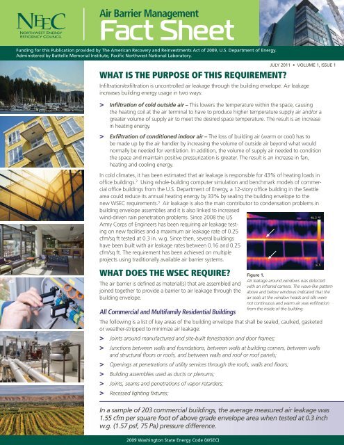
<strong>Air</strong> <strong>Barrier</strong> <strong>Management</strong><strong>Fact</strong> <strong>Sheet</strong>Funding for this Publication provided by The American Recovery and Reinvestments Act of 2009, U.S. Department of <strong>Energy</strong>.Administered by Battelle Memorial Institute, Pacific <strong>Northwest</strong> National Laboratory.WHAT IS THE PURPOSE OF THIS REQUIREMENT?Infiltration/exfiltration is uncontrolled air leakage through the building envelope. <strong>Air</strong> leakageincreases building energy usage in two ways:> Infiltration of cold outside air – This lowers the temperature within the space, causingthe heating coil at the air terminal to have to produce higher temperature supply air and/or agreater volume of supply air to meet the desired space temperature. The result is an increasein heating energy.> Exfiltration of conditioned indoor air – The loss of building air (warm or cool) has tobe made up by the air handler by increasing the volume of outside air beyond what wouldnormally be needed for ventilation. In addition, the volume of supply air needed to conditionthe space and maintain positive pressurization is greater. The result is an increase in fan,heating and cooling energy.In cold climates, it has been estimated that air leakage is responsible for 43% of heating loads inoffice buildings. 2 Using whole-building computer simulation and benchmark models of commercialoffice buildings from the U.S. Department of <strong>Energy</strong>, a 12-story office building in the Seattlearea could reduce its annual heating energy by 33% by sealing the building envelope to thenew WSEC requirements. 3 <strong>Air</strong> leakage is also the main contributor to condensation problems inbuilding envelope assemblies and it is also linked to increasedwind-driven rain penetration problems. Since 2008 the USArmy Corps of Engineers has been requiring air leakage testingon new facilities and a maximum air leakage rate of 0.25cfm/sq ft tested at 0.3 in. w.g. Since then, several buildingshave been built with air leakage rates between 0.16 and 0.25cfm/sq ft. The requirement has been achieved on multipleprojects using traditionally available air barrier systems.WHAT DOES THE WSEC REQUIRE?The air barrier is defined as material(s) that are assembled andjoined together to provide a barrier to air leakage through thebuilding envelope.All Commercial and Multifamily Residential BuildingsJULY 2011 • VOLUME 1, ISSUE 1Figure 1.<strong>Air</strong> leakage around windows was detectedwith an infrared camera. The wave-like patternabove and below windows indicated that theair seals at the window heads and sills werenot continuous and warm air was exfiltrationfrom the inside of the building.The following is a list of key areas of the building envelope that shall be sealed, caulked, gasketedor weather-stripped to minimize air leakage:> Joints around manufactured and site-built fenestration and door frames;> Junctions between walls and foundations, between walls at building corners, between wallsand structural floors or roofs, and between walls and roof or roof panels;> Openings at penetrations of utility services through the roofs, walls and floors;> Building assemblies used as ducts or plenums;> Joints, seams and penetrations of vapor retarders;> Recessed lighting fixtures;In a sample of 203 commercial buildings, the average measured air leakage was1.55 cfm per square foot of above grade envelope area when tested at 0.3 inchw.g. (1.57 psf, 75 Pa) pressure difference.2009 Washington State <strong>Energy</strong> Code (WSEC)
<strong>Air</strong> <strong>Barrier</strong> <strong>Management</strong> <strong>Fact</strong> <strong>Sheet</strong>Figure 3.Installation of fully adhered air-barrier (orangemembrane) including self-adhering flashing inprogress in Central Washington.areas may be requiredto meet air barrier sealingrequirements. Forexample, if the floorand doors separating amechanical penthousefrom the buildingare airtight it can beexcluded from the airbarrier testing. Likewisereceiving dockswith roller doors canbe excluded providedthat the area is enclosed by airtight partitions and floors. Formulti-story buildings being tested by the floor-by-floor methodit is important to identify chases, shafts and wall cavities thatcommunicate one floor to another.Mechanical EngineerIn multi-story buildings, air barrier testing via the HVAC systempressurization method may be more practical than testingvia fan pressurization. The mechanical engineer may facilitatethis approach by providing the following in their HVACsystem design:> A central supply or exhaust fan with a total outdoorairflow capacity capable of producing a pressuredifference of approximately 60 Pa.> An airflow control apparatus to vary the outdoor airsupply rate (such as a speed control or a controldamper in series with the fan).> Tightly fitting dampers or access to cover intake.> <strong>Air</strong>flow measurement methods such as pitot tube,hot-wire anemometer traverse, or pressure compensatedshrouds on rooftop fans are provided on all outdoor airand exhaust air-handling equipment.General ContractorTesting of the air barrier may occur anytime during the constructionschedule when it is determined that the air barrierenclosure is complete. However, the key to a successful airbarrier test requires advance planning. The main steps include:pre-construction review, selection of trades, review trade submittals,sequencing of trades, mock-up assemblies, field testingof assemblies, air barrier QA/QC, whole building air barrierpre-test, trouble shooting, and final testing. Sufficient time fortesting and diagnostics should be included in the constructionschedule. Note that the ASTM testing standard recommendsperforming the tests when outdoor wind conditions are lessthan 4 mph and outdoor temperatures are between 41-95degrees F.The following preparation list provides an example of the stepsnecessary to ensure a safe and accurate test:> Seal or isolate all intentional openings in the building suchas air intake and exhaust louvers, dampers, etc.> Exterior windows and doors are not intentionalopenings and therefore should be included in theenclosure under test in the normal closed position.> Open all interior doors.> Remove some ceiling tiles, approximately 1 per 500 ft 2 .> Fill all plumbing traps with water.> Disabled all combustion equipment.ASTM E1186 Standard Practices for <strong>Air</strong> Leakage SiteDetection in Building Envelopes and <strong>Air</strong> <strong>Barrier</strong> Systems isa recommended resource to assist the general contractor inidentifying and eliminating sources of air leakage. <strong>Air</strong> leakscan consist of many small openings, a few very large openingsunnoticed during test preparation, or a combinationof both. Procedures include neutral buoyancy or theatricalsmoke and infrared diagnostic evaluation by a certifiedthermographer.Sub-ContractorsIt is important to inform all sub-contractors that any penetrationthrough the air barrier can impact the building air leakageperformance. All penetrations for electrical wiring, plumbing,ductwork, technology cabling, etc. must be sealed, caulked orgasketed to ensure these penetrations do not impact air barrierintegrity.ADDITIONAL RESOURCES> U.S. Army Corps of Engineers <strong>Air</strong> Leakage TestProtocol for Measuring <strong>Air</strong> Leakage in Buildings –Available on the NEEC website under <strong>Energy</strong> Codes.> American <strong>Air</strong> <strong>Barrier</strong> Association – www.airbarrier.org> NIBS Guideline 3-2006: Exterior Enclosure TechnicalRequirements for the Commissioning Process,National Institute of Building Sciences, 2006. –http://www.wbdg.org/ccb/browse_doc.php?d=7167.Refer to section related to air barriers.Source:1 Emmerich, S.J. and A.K. Persily. 2005. <strong>Air</strong>tightness of commercialbuildings in the U.S. Proceedings of the 26th IEA Conference of the <strong>Air</strong>Infiltration and Ventilation Center, Brussels, pp 65-70. in ASHRAE 2009Handbook of Fundamentals p 16.25.2 Emmerich, S.J., A.K. Persily, and T.P. McDowell. 2005. Impact of infiltrationon heating and cooling loads in U.S. office buildings. Building andFire Research Laboratory, National Institute of Standards and TechnologyGaithersburg, MD. TESS, Inc., Madison, WI. 9 p.3 Marceau, M.L. and C.J. Norris. April 2010. Demystifying air barriers.Construction Today Magazine.2009 Washington State <strong>Energy</strong> Code (WSEC)
<strong>Air</strong> <strong>Barrier</strong> <strong>Management</strong> <strong>Fact</strong> <strong>Sheet</strong>AIR LEAKAGE CASE STUDY:An <strong>Energy</strong> Concern but also a Sourceof Envelope FailureThere are a number of ongoing discussions in the design andconstruction community regarding new air leakage requirementsproposed and implemented by the International <strong>Energy</strong>Conservation Code, the International Green Building Code,as well as State and Municipal Codes. Most of the discussionsfocus on minimizing air leakage to reduce energy usage andlower carbon footprint. But there is another equally importantreason to design with a continuous air barrier: durability. Thiscase study describes a building envelop failure that was due inpart to lack of continuity of the air barrier.<strong>Air</strong> leakage is by nomeans a new issue todesigners or builders;however, comparedto water leakage, airleakage is sometimesoverlooked as a significantcontribution toenvelope failure. Undercertain conditions, airleakage can be equally as destructive as water leakage.In the case of a 1976 low-rise wood-framed residentialcomplex in the Pacific <strong>Northwest</strong>, air leakage was the causeof 25% of the damage, which required complete enveloperehabilitation. Stucco clad exterior partition walls separateroof decks, suite entrances, and balconies. These architecturalfeatures were extended to include stucco wall build-outs andmetal capped roof build-ups. The roof consists of inverted flatroofs and sloped metal roofs.After previous waterproofingrepairs provedunsuccessful, a detailedbuilding envelopeinvestigation was conducted.Black stainingand mold growth wereconsistently observedon the interior surfacesof the partition walls and roof build-ups. Damage was oftengreater on the interior surfaces of the framing and sheathingrather than on the exterior.The party walls consist of 2x4 double stud walls with a gapof one to two inches between the walls. Partition walls, roofdecks, and roof build-outs consist of wood frame extensions ofthe party walls.Heated air in a buildingis buoyant and exertspressure on the envelope.By the principle ofStack Effect, warm moistair migrated from the interiorof the building intothe party walls, then upinto the partition wallsabove the roof/deck line.Acting as a chimneyfrom the crawlspacesto the roof, the party wall configuration allowed interior airto rise and accumulate in the uninsulated partitions and roofbuild-outs, where it condensed on the cold surfaces, leading torot and failure. The leakage of warm air through the partitionwall was so significant that during rehabilitation, condensationwas observed on the plastic tarps used to cover the partitionwalls that were being repaired.The areas of most advanced decay were those affected by thecombination of water leakage (from outside) and air leakage(from inside). As in this case, problems due to air leakageare not often visible from either the interior or exterior of thebuilding. As such, air leakage issues can go overlooked andunaddressed for years. In this case, building configurationand architectural elements, lack of air barrier continuity, anda lack of designed ventilation for the affected elements, andextended exposure of exterior void spaces to warm air werecontributing factors to the failure.The successful repair consisted of creating a plane of air tightnessusing expanding polyurethane spray foam insulationwhere party walls penetrate the plane of the flat roof andventing the partition walls. The repair minimizes the amountof air leakage into the partition walls and uses venting to allowany moisture that does migrate from interior spaces into thepartition walls to evaporate to the outside.<strong>Air</strong> leakage should be considered as a potential source ofenvelope failure for both new construction and rehabilitationprojects. Appropriate design and construction review of theair barrier is important to improve energy efficiency as well asbuilding envelope durability.1For the complete case study refer to Deamer, D., <strong>Air</strong> Leakageas a Source of Envelope Failure in Lowrise ResidentialBuildings in the Lower Mainland, Morrison Hershfield, 2002.http://www.morrisonhershfield.com/Newsroom/Technical-Papers/Pages/default.aspx.Technical content contributed by:2009 Washington State <strong>Energy</strong> Code (WSEC)