Turtle and Tortoise Newsletter - VET-MAGAZIN.com
Turtle and Tortoise Newsletter - VET-MAGAZIN.com
Turtle and Tortoise Newsletter - VET-MAGAZIN.com

Create successful ePaper yourself
Turn your PDF publications into a flip-book with our unique Google optimized e-Paper software.
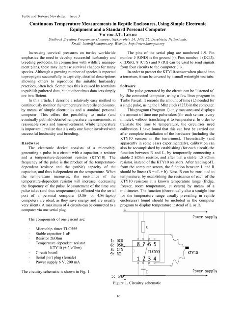
<strong>Turtle</strong> <strong>and</strong> <strong>Tortoise</strong> <strong>Newsletter</strong>, Issue 3Continuous Temperature Measurements in Reptile Enclosures, Using Simple ElectronicEquipment <strong>and</strong> a St<strong>and</strong>ard Personal ComputerVICTOR J.T. LOEHRStudbook Breeding Programme Homopus, Nipkowplein 24, 3402 EC IJsselstein, Netherl<strong>and</strong>s,Email: loehr@homopus.org, Website: http://www.homopus.orgIncreasing survival pressures on turtles worldwideemphasize the need to develop successful husb<strong>and</strong>ry <strong>and</strong>breeding protocols. In conjunction with wildlife managementplans, these may increase survival chances for manyspecies. Although a growing number of species is reportedto propagate successfully in captivity, detailed descriptionsallowing others to reproduce the suitable husb<strong>and</strong>rypractices, often lack. Sometimes this is caused by restraintsto publish gathered data, but at other times data sets simplyare insufficient.In this article, I describe a relatively easy method tocontinuously monitor the temperature in reptile enclosures,by means of simple electronics <strong>and</strong> a st<strong>and</strong>ard personal<strong>com</strong>puter. This offers the possibility to make (<strong>and</strong>eventually publish) detailed temperature measurements, atreasonable costs <strong>and</strong> time-investment. While temperatureis important, I realize that it is only one factor involved withsuccessful husb<strong>and</strong>ry <strong>and</strong> breeding.HardwareThe electronic device consists of a microchip,generating a pulse in a circuit with a capacitor, a resistor<strong>and</strong> a temperature-dependent resistor (KTY10). Thefrequency of the pulse is the product of the temperaturedependentresistor <strong>and</strong> the (stable) capacity of thecapacitor, <strong>and</strong> thus is dependent on the temperature. Whenthe temperature increases, the resistance of thetemperature-dependent resistor will increase, decreasingthe frequency of the pulse. Measurement of the time onepulse takes (<strong>and</strong> thus temperature) is effected via the serialport of a personal <strong>com</strong>puter (3.86- or 4.86-laptop<strong>com</strong>puters are ideal, as they save energy <strong>and</strong> are usuallyvery silent). A maximum of 4 circuits can be connected to a<strong>com</strong>puter via one serial plug.The pins of the serial plug are numbered 1-9. Pinnumber 5 (GND) is the ground (-). Pins number 1 (DCD),6 (DSR), 8 (CTS) <strong>and</strong> 9 (RI) can be used to send signalsfrom four circuits to the <strong>com</strong>puter (+).In order to protect the KTY10-sensor when placed intoa terrarium, it can be covered by a small watertight test tube.SoftwareThe pulse generated by the circuit can be ‘listened to’by the connected <strong>com</strong>puter, using a few lines-program inTurbo Pascal. It records the amount of time (L) needed fora single pulse, using the 1 Mhz clock (8253) in the <strong>com</strong>puter.This program (Program 1) only measures <strong>and</strong> displaysthe amount of time one pulse takes (for each sensor, everyminute), without translating it to temperature. In order totranslate the time to temperature, the circuitries needcalibration. I have found that this can best be carried outafter <strong>com</strong>plete installation of the hardware (including theKTY10 sensors in the terrariums). Theoretically (<strong>and</strong>apparently in some cases experimentally), calibration canalso be ac<strong>com</strong>plished by establishing (for each circuit) thefunction between R <strong>and</strong> L, by temporarily connecting astable 2 kOhm resistor, <strong>and</strong> after that a stable 1.5 kOhmresistor, instead of the KTY10 resistors. After reading of Lfrom the <strong>com</strong>puter screen, the function between L <strong>and</strong> Rshould be linear (R = aL + b). Next, R can be translated totemperature, by establishing the resistance of each of theKTY10 resistors at a known temperature range (fridge,freezer, room temperature, et cetera) by means of amultimeter. The function (theoretically also a straight linefor the temperature range usually prevailing in reptileenclosures) found should be included in the <strong>com</strong>puterprogram to display temperature instead of L or R.The <strong>com</strong>ponents of one circuit are:· Microchip timer TLC555· Stable capacitor 1 uF· Resistor 2kOhm· Temperature dependent resistorKTY10 (± 2 kOhm)· Circuit board· Serial port plug (female)· Power supply 6 V, 200 mAThe circuitry schematic is shown in Fig. 1.Figure 1. Circuitry schematic16