MAXX Series 3 Owner's Manual - Wilson Audio
MAXX Series 3 Owner's Manual - Wilson Audio
MAXX Series 3 Owner's Manual - Wilson Audio

Create successful ePaper yourself
Turn your PDF publications into a flip-book with our unique Google optimized e-Paper software.
<strong>MAXX</strong> <strong>Series</strong> 3 Owner’s <strong>Manual</strong>
T a b l e o f Co n t e n T SContents<strong>MAXX</strong> Se r i e s 3 Ow n e r ’ s Ma n u a l 1S e c t i o n 1 – In t r o d u c t i o n 7S e c t i o n 1.1 – In t r o d u c t i o n 9A s p h e r i c a l Pr o p a g a t i o n d e l a y 10S e c t i o n 2 – In Yo u r Ro o m 13S e c t i o n 2.1 – Ro o m Ac o u s t i c s 15F i n a l Li s t e n i n g Ro o m Se t u p (Vo i c i n g ) 15Z o n e o f Ne u t r a l i t y 15S e c t i o n 2.2 – Ro o m Re f l e c t i o n s 17S l a p Ec h o 18S t a n d i n g Wa v e s 20C o m b Fi l t e r Ef f e c t 21S e c t i o n 2.3 – Re s o n a n c e s 22S t r u c t u r a l Re s o n a n c e 22V o l u m e Re s o n a n c e 23S e c t i o n 2.4 – Yo u r Ro o m 23R o o m Sh a p e s 23<strong>MAXX</strong> Se r i e s 3 in a De d i c a t e d Ho m e Th e a t e r 25S p e a k e r Pl a c e m e n t Ve r s u s Li s t e n i n g Po s i t i o n 25S p e a k e r Orientation 26S u m m a r y 27S e c t i o n 3 – Un c r a t i n g t h e <strong>MAXX</strong> 29S e c t i o n 3.1 – Un c r a t i n g t h e <strong>MAXX</strong> 31I nitial Ch e c k 31T o o l s Re q u i r e d 31<strong>Wilson</strong> <strong>Audio</strong> Specialties3
<strong>MAXX</strong> Se r i e s 3 Ow n e r ’ s Ma n u a lU n c r a t i n g t h e Wo o f e r Mo d u l e s 32U n p a c k i n g t h e Wo o f e r 32U n c r a t i n g t h e Up p e r Ar r a y Mo d u l e s 32C r a t e Co n t e n t s Ch e c k l i s t 33S e c t i o n 4 – As s e m b l y 35S e c t i o n 4.1 – In i t i a l As s e m b l y 37R e m o v i n g t h e Pr o t e c t i v e Fi l m 37S e c t i o n 4.2 – Ge o m e t r i c Ti m e Do m a i n Al i g n m e n t 38M a t e r i a l s Re q u i r e d 38P r o p a g a t i o n d e l a y Al i g n m e n t 38R o o m Se t u p 39A l i g n m e n t Pr o c e d u r e 39S e c t i o n 4.3 – Mo u n t i n g t h e Lo w e r Tw e e t e r /Mi dM o d u l e 43M a t e r i a l s Re q u i r e d 43M o u n t i n g Pr o c e d u r e 43I n s t a l l t h e Lo w e r Tw e e t e r /Mi d r a n g e Mo d u l e 43S e c t i o n 4.4 – Mo u n t i n g t h e Up p e r Mi d r a n g e Mo d u l e 45S e c t i o n 4.5 – Co n n e c t i n g Up p e r Mo d u l e s ’ Si g n a l Ca b l e 4 5S e c t i o n 4.6 – Lo c k i n g Do w n Th e Up p e r Mo d u l e s 47M a t e r i a l s Re q u i r e d 47I n s t a l l i n g Te t h e r Bo l t in t h e Up p e r Mi d r a n g e Mo d u l e 47S e c t i o n 4.7 – Sp i k e In s t a l l a t i o n 47S p i k e As s e m b l y 47S e c t i o n 4.8 – Us i n g t h e Li f t t o In s t a l l Sp i k e s 49M a t e r i a l s Re q u i r e d 49I n s t a l l a t i o n Pr o c e d u r e 494<strong>Wilson</strong> <strong>Audio</strong> Specialties
T a b l e o f Co n t e n TSL e v e l i n g t h e <strong>MAXX</strong> 51Se c t i o n 4.9 – Re s i s t o r s 52W o o f e r Da m p i n g Re s i s t o r 52S e c t i o n 4.95 – Br e a k - i n Pe r i o d 53S e c t i o n 5 – Ca r e o f <strong>MAXX</strong> 55S e c t i o n 5.1 – Ca r e o f t h e Pa i n t e d Fi n i s h 57C a r e o f t h e Gr i l l 58S e c t i o n 5.2 – En c l o s u r e Co n s t r u c t i o n 59M a t e r i a l 59A d h e s i v e 59C o n c l u s i o n 60S e c t i o n 6 – Tr o u b l e s h o o t i n g 61S e c t i o n 6.1 – Tr o u b l e s h o o t i n g 63S e c t i o n 7 – Sy s t e m Sp e c i f i c a t i o n s 67S e c t i o n 7.1 – Sp e c i f i c a t i o n s : 69S e c t i o n 7.2 – <strong>MAXX</strong> Di m e n s i o n s 70S e c t i o n 8 – Pr o p a g a t i o n d e l a y Ta b l e s 71N u m b e r 1: Lo w e r Tw e e t e r /Mi d r a n g e Mo d u l e Sp i k e Le n g t h 73N u m b e r 2: Lo w e r Tw e e t e r /Mi d r a n g e Mo d u l e Bl o c k Po s i t i o n 73N u m b e r 3: Lo w e r Tw e e t e r /Mi d r a n g e Mo d u l e Bl o c k St e p 74N u m b e r 4: Up p e r Mi d r a n g e Mo d u l e Sp i k e Le n g t h 75N u m b e r 5: Up p e r Mi d r a n g e Mo d u l e Sp i k e De t e n t Lo c a t i o n 75S e c t i o n 9 – Wa r r a n t y Se c t i o n 77S e c t i o n 9.0 – Wa r r a n t y In f o r m a t i o n 79<strong>Wilson</strong> <strong>Audio</strong> Specialties5
S e c t i o n 1.1 – In t r o d u c t i o nSection 1.1 – IntroductionFrom all of us at <strong>Wilson</strong> <strong>Audio</strong> Specialties — thank you for purchasing the <strong>MAXX</strong> ®<strong>Series</strong> 3 loudspeaker. The information contained within the pages of this manual willinform and instruct on the proper assembly, set up, and long term care of your <strong>MAXX</strong><strong>Series</strong> 3s.The original <strong>MAXX</strong> arrived with a clear design objective: create a loudspeaker endowedwith similar authority and dynamic range as <strong>Wilson</strong>’s flagship speaker, the originalX-1 Grand SLAMM ® , but in a less complex and demanding package.In the subsequent years, Dave <strong>Wilson</strong> and his design team discovered ways to improvethe <strong>MAXX</strong>, hence the <strong>Series</strong> 2. They also came to realize that, as good as it was,by one important benchmark—propagation delay—the <strong>MAXX</strong> <strong>Series</strong> 2 platform was incapableof further improvement.Among the technical innovations of the <strong>MAXX</strong> <strong>Series</strong> 3:• All-new midrange driver evolved from the revolutionary Alexandria<strong>Series</strong> 2 midrange unit.• All-new upper module design with two upper modules replacing thesingle module of the original <strong>MAXX</strong>. Although it is far more accuratethan competing designs, the single, three-driver head of both<strong>MAXX</strong> <strong>Series</strong> 1 and <strong>Series</strong> 2 runs into the laws of geometry and physics.It is simply impossible to align three drivers in one module forideal propagation delay. The solution? Divide <strong>MAXX</strong>’s dual midrangedrivers and tweeter into two upper modules and introduce AsphericalGroup Delay.• Aspherical Propagation Delay. Achieving near perfect alignment atthe listening position requires controlling both the rotational angleof the head (for proper dispersion) and the time alignment of thedriver (its relative distance to the listener). <strong>MAXX</strong> <strong>Series</strong> 3 joins theAlexandria as the only speaker to feature this technology.<strong>Wilson</strong> <strong>Audio</strong> Specialties9
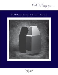
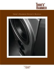
<strong>MAXX</strong> Se r i e s 3 Ow n e r ’ s Ma n u a l• New crossovers. Applying new technology adapted from the <strong>Series</strong>2 Alexandria. Further work in reducing propagation delay jitter haslowered the noise floor and has increased overall resolution, particularlyin the time between transients.• New resistor connector plate with reduced resonance and greaterheat dissipation. The new plate is user-accessible and is located inthe rear plane of the woofer enclosure.Aspherical Propagation delayA musical waveform is a complexoverlay of frequencies, amplitudes, andphase relationships. With current technology,no single transducer can reproducethe full range of music at realisticsound pressure levels while maintainingconsistent dispersion. The solutionis the multiple driver array, with specificdrivers dedicated to various portionsof the frequency range. Multiple driversintroduce their own set of problems. Achallenge typically ignored by speakerdesigners is preserving the precise timerelationships of the leading edge of themusical waveform.The key to solving this problemlies in <strong>Wilson</strong>’s innovative and patentedAdjustable Propagation Delay technology,which employs movable modulesFig u r e 1 – <strong>MAXX</strong>’s Mo d u l e s Mo v e As p h e r i c a l lyt o Co r r e c t Pr o p a g at i o n De l a y10<strong>Wilson</strong> <strong>Audio</strong> Specialties
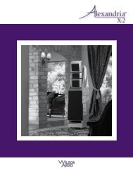
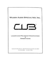
S e c t i o n 1.1 – In t r o d u c t i o nthat allow the individual adjustment of the drivers in the time domain. Using this technology,each driver’s waveform propagation “matches up” with the other drivers in thesystem in such a way as to create the sonic equivalent of a single point source. Certainother loudspeaker makers recognize the need to correctly align their drivers, but they doFig u r e 2a - Ty p i c a l l o u d s p e a k e r s e x h i b i t l e s s t h a n o p t i m u mp r o pa g at i o n d e l a y a n d d i s p e r s i o n c h a r a c t e r i s t i c s . Th e s o u n dq u a l i t y is co m p r o m i s e d fo r al l li s t e n e r s in al l ro o m s .Fig u r e 2b - As p h e r i c a l Pr o pa g at i o n De l a y o p t i m i z e s d r i v e r/ro o m inte r a c t i o n f o r a v a r i e t y o f s i t u at i o n s . Th i s p r o v i d e s c o n s i s t e n t ly o p t i -m i z e d re s u lt s in a wi d e ra n g e of ro o m s an d li s t e n i n g po s i t i o n s .Fig u r e 2 – <strong>MAXX</strong>’s Mo d u l e s Mo v e As p h e r i c a l ly to Co r r e c t Pr o p a g at i o n De l a y<strong>Wilson</strong> <strong>Audio</strong> Specialties11
<strong>MAXX</strong> Se r i e s 3 Ow n e r ’ s Ma n u a lso for only one theoretical listening position.The fact is, misalignment of the drivers by fractions of an inch will audibly degradetransient accuracy, soundstage height, depth, and width. Misalignment of the drivers willalso introduce tonal anomalies that destroy the otherwise convincing “presence” of aninstrument or a singer’s voice. <strong>Wilson</strong>’s solution for propagation delay correction haslong set the standard for precise driver positioning in order to insure correct time alignmentfor a wide range of real room listening distances and ear heights.The <strong>MAXX</strong> cabinet is a further evolution of <strong>Wilson</strong>’s philosophy that truly greatforms follow a corresponding function. It is a visual metaphor for the solution <strong>Wilson</strong><strong>Audio</strong> pioneered to address issues of phase coherence exacerbated by large speaker systems.Typical of the creative process, the solution itself is an analogy to the field of opticsand the design of wide-angle lenses. The means of maintaining edge-to-edge sharpnessat both close and far focusing distances for a high quality wide-angle lens suggesteda solution to the similar problem of time domain accuracy for large speaker systems atboth near and far listening positions.With <strong>MAXX</strong> <strong>Series</strong> 3, <strong>Wilson</strong> <strong>Audio</strong> takes this concept a logical step further, addressingthe issue of optimal driver dispersion in the large cabinet system. Ideal driverdispersion for both near and far listening positions requires the drivers be adjustable notonly forward and back, but also able to rotate on their polar axes.With <strong>MAXX</strong> <strong>Series</strong> 3, you and others you listen with, will hear your favorite recordingsand soundtracks with true time coherency, full frequency range, unfettered dynamics,and vanishingly low distortion. The improvement in realism wrought by <strong>MAXX</strong> <strong>Series</strong>3 is delightfully revolutionary.12<strong>Wilson</strong> <strong>Audio</strong> Specialties
Section 2 – In Your Room
<strong>MAXX</strong> Se r i e s 3 Ow n e r ’ s Ma n u a l14<strong>Wilson</strong> <strong>Audio</strong> Specialties
S e c t i o n 2.1 – Ro o m Ac o u s t i c sSection 2.1 – Room AcousticsYou are surely excited about setting up your <strong>MAXX</strong> <strong>Series</strong> 3 loudspeakers and doingsome listening, but before you begin, we would like to discuss some of the importantroom acoustical information that will help you set up your loudspeakers properly.Final Listening Room Setup (Voicing)For a speaker system its size, the <strong>MAXX</strong> <strong>Series</strong> 3 is unmatched in its ability to reproducethe musical event. It is truly state-of-the-art. However, room acoustics and boundaryinteractions affect the sound of a loudspeaker to such a large degree that poor setupcan seriously degrade your enjoyment of even the finest loudspeaker.Therefore, we offer the following section, which will present some guidelines onroom acoustics and their interactions with loudspeakers. While we will also outline somedetailed suggestions on the setup of the <strong>MAXX</strong>s, we strongly suggest that you have yourlocal <strong>Wilson</strong> <strong>Audio</strong> dealer perform the final speaker “voicing” with you. <strong>Wilson</strong> dealersare specially trained in setting up <strong>Wilson</strong> loudspeakers and will ensure that you realizethe full value of your purchase.Zone of NeutralityThe “Zone of Neutrality” is an area in your room where the speakers will soundmost natural. This location is where the speakers interact the least with adjacent roomboundaries. It is important to have a clear working space while determining the Zone ofNeutrality.The following is a simple method to locate the Zone of Neutrality within your listeningenvironment:1. Stand against the wall BEHIND the location (the rear wall) whereyou intend to position your <strong>MAXX</strong>s. Speaking in a moderately loudvoice and at a constant volume, project your voice out into theroom. Your voice will have an overly heavy, “chesty” quality be-<strong>Wilson</strong> <strong>Audio</strong> Specialties15
<strong>MAXX</strong> Se r i e s 3 Ow n e r ’ s Ma n u a lcause of your proximity to the rear wall.2. While speaking, slowly move out into the room, progressing in adirection parallel to and at least two and half feet from the nearestsidewall. It is helpful to have another listener seated in the listeningposition to assist you during this process. Listen to how yourvoice “frees up” from the added bass energy imparted by the rearwall boundary. Also notice that your voice is quite spatially diffuse(to your assistant, your voice will sound spatially large anddifficult to localize) as you begin to ease away from the rear wallbehind you.3. At some point during your progression forward into the room, youwill observe a sonic transition in your voice; it will sound moretonally correct and less spatially diffuse (your assistant can nowprecisely localize the exact origin of your voice). When you hearthis transition, you have entered the inner edge of the Zone ofNeutrality. Place a piece of tape on the floor to mark this location.Although it will vary from room to room, the zone in most roomsbegins between two and a half to three feet from the rear wall.4. Continue to walk slowly away from the rear wall. After some distance,usually one to two feet past the first piece of tape, you willbegin to hear your voice lose focus and appear to reflect (echo) infront of you. This is caused by the return of the room’s boundarycontribution; your voice is now interacting with the opposite wall.At the point where you begin to hear the reflected sound of yourvoice, you have reached the outer edge of the Zone of Neutrality.Place a piece of tape on the floor and mark this location. The distancebetween the “inner” and “outer” edge tape marks is usuallybetween eight inches (for small, interactive rooms) and two feet(for large, very neutral rooms).5. Now position yourself against the side wall perpendicular to the intendedspeaker location. Stand between the two tape marks. Usingthe same procedure as above, begin moving into the room toward16<strong>Wilson</strong> <strong>Audio</strong> Specialties
<strong>MAXX</strong> Se r i e s 3 Ow n e r ’ s Ma n u a lroom as much. Placed properly, diffusers create a smoother and more open sound. Somediffusers, due to their construction, create narrow midrange peaks and suck-out thewarmth region. Do not use diffusers on the wall behind the speakers or on the sidewallsdirectly beside the speakers. It is our experience that all of these room treatment devicesshould be used judiciously.Standing WavesAnother type of reflection phenomenon is “standing waves.” Standing waves causethe unnatural boosting or accentuation of certain frequencies, typically in the bass, tobe found at certain discreet locations in the room. These locations differ according toroom dimension and size. A room that supports severe standing waves creates difficultyin setup. In these rooms, the speaker will sound radically different as it is moved around.The effects of standing waves on a loudspeaker’s performance are primarily in the areaslisted.• Low Frequency Tonal balance• Resolution of low-level detail• SoundstagingStanding waves are more difficult to correct than slap echo because they tend tooccur at a lower frequency. Absorbent materials, such as RPG Absorbor ® , are ineffectiveat controlling reflections in the bass region. Moving speakers about slightly in the roomis, for most people, their only control over standing waves. Sometimes a change of placementof as little as two or three inches can dramatically alter the tonal balance of a smallsystem.Fortunately, minor low frequency standing waves are well controlled by positioningRPG Modex Corner panels or ASC Tube Traps or in the corners of the room. Very seri-20<strong>Wilson</strong> <strong>Audio</strong> Specialties
S e c t i o n 2.2 – Ro o m Re f l e c t i o n sous low frequency accentuation usually requires a custom-designed bass trap system.Low frequency standing waves can be particularly troublesome in rooms constructedof concrete or brick. These materials trap the bass in the room unless it is allowed toleak out of the room through windows and doors.In general, placement of the speaker in a corner will excite the maximal number ofstanding waves in a room and is to be avoided for most direct radiator, full-range loudspeakersystems. Some benefit is achieved by placing the stereo pair of loudspeakersslightly asymmetrically in the listening room. This is so the standing waves caused by thedistance between one speaker and its adjacent walls and floors are not the same as thestanding wave frequencies excited by the dimensions in the other channel.Comb Filter EffectThe “comb filter” effect is a special type of standing wave noticeable primarily athigher frequencies and shorter wavelengths.Acoustical comb filtering occurs when sound from a single source, such as a loudspeaker,is directed toward a microphone or listener from a distance. The first sound toreach the microphone is the direct sound, followed by a delayed, reflected sound. Atcertain frequencies, cancellation occurs because the reflected sound lags in phase relativeto the direct sound. This cancellation is most apparent where the two frequencies are180 degrees out of phase. Further, there is augmentation at other frequencies where thedirect and the reflected sounds arrive in phase. Because it is a function of wavelength,the comb filter effect will notch out portions of the audio spectrum at linearly spacedintervals. Subjectively, comb filter effect evidences itself as follows:• Added roughness to the sound• Reduction of harmonic richness<strong>Wilson</strong> <strong>Audio</strong> Specialties21
<strong>MAXX</strong> Se r i e s 3 Ow n e r ’ s Ma n u a l• Smearing of lateral soundstage image focus and placementComb filter effects are often caused by floor or ceiling reflection and sometimesside wall reflections. They are best controlled by very careful speaker placement and bythe judicious placement of RPG Absorbor ® or air duct panels applied to that part of thewall where the reflection occurs.Section 2.3 – ResonancesResonance in listening rooms is generally caused by two sources:• Structures within the listening room.• The volume of air itself within the listening room.Structural ResonanceStructural resonances are familiar to most people as buzzes and rattles, but this typeof resonance usually only occurs at extremely high volume levels and is usually maskedby the music. In many wood frame rooms the most common type of structural resonanceproblem is “booming” of walls and floors. You can test for these very easily by tappingthe wall with the palm of your hand or stomping on the floor. Most rooms exhibit midbass“boom” when struck. The loudspeaker playing in the room also excites these resonances.To give you an idea of what the perfect wall would sound like, imagine rappingyour hand against the side of a mountain. Structural wall resonances generally occur inthe low to mid-bass frequencies and add a false fullness to the tonal balance. They, too,are more prominent at louder levels, but their contribution to the sound of the speakeris more progressive. Rattling windows, picture frames, lamp shades, etc., can generallybe silenced with small pieces of caulk or with blocks of felt. However, short of actuallyadding additional layers of sheet rock to flimsy walls, there is little that can be done toeliminate wall resonances.22<strong>Wilson</strong> <strong>Audio</strong> Specialties
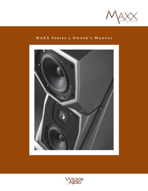
S e c t i o n 2.4 – Yo u r Ro o mVolume ResonanceThe physical dimensions and volume of air in a room will also support standingwave modes and resonances at frequencies determined by the size of that room. Largerrooms will resonate at a lower frequency and have more complex (better) modal distributionsthan will smaller rooms. Volume resonances, wall panel resonances, and lowfrequency standing waves combine to form a low frequency coloration in the sound. Atits worst, it is a grossly exaggerated fullness, which tends to obscure detail and distortthe natural tonal balance of the speaker system.Occasionally, however, there is just enough resonance to give a little added warmthto the sound – an addition some listeners prefer. Careful placement of loudspeakers inthe room can dramatically reduce the speakers’ destructive interaction with low frequencymodes. ASC Tube Traps are effective in reducing some of this low frequencyroom coloration. Custom designed bass traps, such as perforated Helmholtz resonators,provide the greatest degree of low frequency control.Section 2.4 – Your RoomRoom ShapesStanding waves are pressure waves propagated by the interaction of sound and opposingparallel walls. This interaction creates patterns of low and high acoustical pressurezones that accentuate and attenuate particular frequencies. Those frequencies aredependent on room size and dimension.There are three basic shapes for most rooms: square, rectangular, and L-shaped (seeFigure 4).A perfectly square room is the most difficult room in which to set up speakers.By virtue of its shape, a square room is the perfect medium for building and sustainingstanding waves. These rooms heavily influence the music played by loudspeakers, greatly<strong>Wilson</strong> <strong>Audio</strong> Specialties23
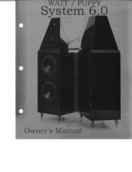
<strong>MAXX</strong> Se r i e s 3 Ow n e r ’ s Ma n u a ldiminishing the listening experience.Long, narrow, rectangularrooms also pose their ownspecial acoustical problems forspeaker setup. They have theability to create several standingwave nodes, which will havedifferent standing wave frequencyexaggerations depending onwhere you are sitting. Additionally,these long rooms are oftenquite lean in the bass near thecenter of the room. Rectangularrooms are still preferred tosquare rooms because, by havingtwo sets of dissimilar lengthwalls, standing waves are not asstrongly reinforced and will dissipatemore quickly than in asquare room. In these rooms, thepreferred speaker position forspatial placement and midrangeresolution would be on the longerwalls. Bass response wouldbe reinforced by speaker placementon the short walls.Fig u r e 4 – Po s s i b l e Lo u d s p e a k e r Pl a c e m e n t withinVar i o u s Ro o m Sh a p e s24<strong>Wilson</strong> <strong>Audio</strong> Specialties
S e c t i o n 2.4 – Yo u r Ro o mIn many cases, L-shaped rooms (see Figure 4) offer the best environment for speakersetup. Ideally, speakers should be set up along the primary (longest) leg of the room.They should fire from the end of the leg (short wall) toward the L, or they should be alongthe longest wall. In this way, both speakers are firing the same distance to the back wall.The asymmetry of the walls in L-shaped rooms resists the buildup of standing waves (seeFigure 4).<strong>MAXX</strong> <strong>Series</strong> 3 in a Dedicated Home TheaterHome theaters can be organized many different ways. Some use rows of couches.Others use rows of multiple chairs.In addition to watching movies, most users want to listen to two-channel music atthe highest quality possible. It is desirable, therefore, to choose a single optimum seatingposition in a home theater and build the rest of the seating positions around this position.If your optimum position is located on a couch, you should center the loudspeakerson the middle position of the couch.If the seating area consists of multiple rows of chairs, the second row should beoptimized for the best sound quality. Odd numbers of chairs arranged in rows work bestas this will allow a single chair to be positioned in the center. This approach will alsoprovide the best overall sound for the greatest number of seats.Speaker Placement Versus Listening PositionThe location of your listening position is almost as important as the careful setup ofyour <strong>MAXX</strong> speakers. The listening position should ideally be no more than 1.1 to 1.25times the distance between the tweeters on each speaker. Therefore, in a long, rectangularroom of 12’ x 18’, if the speaker tweeters are going to be 9’ apart, you should besitting 9’11’’ to 11’3’’ from the speaker. This would be more than halfway down the longaxis of the room.<strong>Wilson</strong> <strong>Audio</strong> Specialties25
<strong>MAXX</strong> Se r i e s 3 Ow n e r ’ s Ma n u a lMany people place the speakers on one end and sit at the other end of the room.This approach will not yield the finest sound. Carefully consider your listening position.Our experience has shown that any listening position that places your head closer than14” from a room boundary will diminish the sonic results of your listening.Decide where you want your favorite listening position to be. Please remember thatyour <strong>MAXX</strong> <strong>Series</strong> 3 will fill almost any room with the most beautiful sound available.Because the propagation delay is adjustable on the <strong>MAXX</strong>s, if you take care in placingyour new speakers, you will optimize <strong>MAXX</strong>’s performance in your room.Speaker OrientationSpeaker placement and orientation are two of the most important considerationsin obtaining superior sound. The first thing you need to do is eliminate the sidewalls asa sonic influence in your system. Speakers placed too close to the sidewalls will sufferfrom a strong primary reflection. This can cause out-of-phase cancellations, or comb filtering,which will cancel some frequencies and change the tonal balance of the music.The <strong>Wilson</strong> <strong>Audio</strong> Setup Procedure (Section 2.1) is the best method with which to positionyour loudspeakers. Start with the speakers about 18” from each wall and, if you needto move them relative to the side wall, move them away from the wall, not closer.A very important aspect of speaker placement is how far from the back wall to placethe speakers. The closer a loudspeaker is to the back wall, the more pronounced the lowbass energy and centering of the image will be. However, this comes at a definite reductionin stage size and bloom as well as a deterioration of upper bass quality. You mustfind the proper balance of these two factors, but remember, if you are partial to bassresponse or air and bloom, do not overcompensate your adjustments to maximize theseeffects. Overcompensated systems are sometimes exciting in the short-term, but longtermsatisfaction is always achieved through proper balance.The <strong>Series</strong> 3 <strong>MAXX</strong> is designed for maximum phase coherence when each speaker26<strong>Wilson</strong> <strong>Audio</strong> Specialties
S e c t i o n 2.4 – Yo u r Ro o mis aimed directly at the listener or microphone. Thus, your <strong>MAXX</strong> should be “toed in.”In other words, the listener, when seated in the listening position looking forward withhis/her head in a rested position, should just barely see the surface of the inner side ofeach <strong>MAXX</strong>. Toeing in the speakers provides meaningful improvements in resolution oflow-level detail in the midrange as well as appreciable improvements in soundstagingperformance.SummaryIn summary, for optimal tonal balance accuracy, resolution of low level detail,and soundstaging performance, the <strong>MAXX</strong> <strong>Series</strong> 3 should be positioned as outlined inthis section. Ideally, the speakers should not be positioned too far from the listener ifmaximum resolution of low-level detail is required. If possible, the speakers should bepositioned somewhat out into the room, slightly asymmetrically vis-a-vis the side andrear walls. The speakers should be “toed in” toward the listener, preferably so that thelistener, at his seated position, can barely see the surface of the inner side of the <strong>MAXX</strong>as he/she faces the speaker. It is recommended that a distance of two to three feet, andpossibly more, be maintained between the <strong>MAXX</strong> and the rear walls and that a distanceof at least two feet be maintained between the front panel of the <strong>MAXX</strong> and reflectiveside walls. Depending on the room, judicious, but not excessive, use of sound absorbentmaterials will reduce the space requirement.By following the guidelines in this manual, your new <strong>MAXX</strong> <strong>Series</strong> 3 loudspeakerscan provide you with a lifetime of pure music reproduction.<strong>Wilson</strong> <strong>Audio</strong> Specialties27
<strong>MAXX</strong> Se r i e s 3 Ow n e r ’ s Ma n u a l<strong>Wilson</strong> <strong>Audio</strong> Specialties
Section 3 – Uncrating the <strong>MAXX</strong>
<strong>MAXX</strong> Se r i e s 3 Ow n e r ’ s Ma n u a l30<strong>Wilson</strong> <strong>Audio</strong> Specialties
S e c t i o n 3.1 – Un c r a t i n g t h e <strong>MAXX</strong>Note: In order to realize the capabilities of the <strong>MAXX</strong>, we strongly recommend thatyou have it installed by a trained <strong>Wilson</strong> <strong>Audio</strong> installer. Your dealer will have a persontrained in the art of the <strong>MAXX</strong> installation, including the safe method to unpackyour loudspeakers.Note: You will have several modules to unpack that will need to be separated intoright and left channels. Clear out two spaces, one for your left and one for your rightchannel modules. Place the ODD numbered modules in the LEFT channel section andthe EVEN in the RIGHT channel section. Prior to assembly, stage the modules awayfrom the area where the speakers are to be assembled. This will avoid clutter in thework area that can result in damage toyour loudspeakers.Section 3.1 – Uncrating the<strong>MAXX</strong>Initial CheckThe <strong>MAXX</strong> is shipped in threewooden crates. Upon receiving thesecrates, please check their condition. Ifany of the crates are damaged, pleasereport it to the shipping company immediatelyfor insurance verification.Tools Required• Metal shears• Variable speed, reversibleelectric drill• Phillips head drive bitFig u r e 5 - Wo o f e r Mo d u l e<strong>Wilson</strong> <strong>Audio</strong> Specialties31
<strong>MAXX</strong> Se r i e s 3 Ow n e r ’ s Ma n u a lUncrating the Woofer ModulesA minimum of two strong adults is required to set up the system. Locate the twolargest crates labeled “Woofer Module.” These contain the woofer enclosures and are thefirst components of the system to unpack (see Figure 5).Note: These two woofer enclosures are very heavy and when moving or lifting, careshould be taken in order to prevent injury.Unpacking the Woofer1. Open the top of each crate and determine the side where the castersare connected to the bottom of the woofer module.2. Remove the packing material from between the casters. Rotate thecrate up on its end so that the casters on the woofer are toward thefloor.3. While one person holds the crate, roll the woofer enclosure outof the crate. Be very careful not to scratch the module during thisprocess.4. Finally, move the woofer cabinets over to the “Zone of Neutrality”as determined by the <strong>Wilson</strong> <strong>Audio</strong> Setup Procedure outlined. Ifyou have not yet performed this room analysis, please refer to Section2.1 of this manual. Reminder: Place the odd serial numberedwoofer on the LEFT and the even numbered woofer on the RIGHT.5. Remove the empty woofer crates from the room.Uncrating the Upper Array Modules1. Locate the crate labeled “Upper Modules.” Remove the four uppermodules (two for each channel), from the crate (see Figure 6). Itis very important to ensure that each of the modules are matchedto one another by serial number. The serial tags are located on theunderside of each module. Be very careful in unpacking the re-32<strong>Wilson</strong> <strong>Audio</strong> Specialties
maining modules to avoid chipping the finish.S e c t i o n 3.1 – Un c r a t i n g t h e <strong>MAXX</strong>2. Stage these items away from traffic flow, preferably against a wallwith drivers facing the wall.3. Remove the empty crates from the room.Crate Contents ChecklistNow that you have everything unpacked,you can inventory your items.1 - Owners manual2 - Woofer modules (left &right channel)2 - Lower Tweeter/MidrangeModules (left & right channel)2 - Upper Midrange modules(left & right channel)2 - Woofer grills2 - Lower Tweeter/MidrangegrillsUpp e r Mi d r a n g e Mo d u l e2 - Upper Midrange grills1 - Lifting Jack and wrench8 - Spikes, with nuts8 - Woofer Mechanical Diode8 - 3/8 x 1 1/2” Set screws1 - 9/16” Combo wrench1 - 3/16” Long-arm Allenwrench1 - 5/32” Allen wrenchLow e r Tw e e t e r/Mi d r a n g e Mo d u l e1 - Caster wrench1 - 1/2” Binding post wrenchFig u r e 6 - Un c r at e Up p e r Mo d u l e s<strong>Wilson</strong> <strong>Audio</strong> Specialties33
<strong>MAXX</strong> Se r i e s 3 Ow n e r ’ s Ma n u a l3/8” Allen wrench1/8” Allen wrench3/32” Allen wrench8 - “A” spikes2 - “B” spikes2 - “C” spikes2 - “D” spikes2 - “E” spikes2 - “F” spikes2 - “G” spikes2 - #2 spikes2 - #3 spikes4 - <strong>MAXX</strong> 3 Tether Bolts4 - <strong>MAXX</strong> 3 Tether Caps2 - Alignment Blocks (installed)2 - 1/2” Alignment Block Allen Bolt1 - Polishing cloths8 - Large Brass spike padsComplete set of resistors:4 - 6.0 ohm tweeter resistor4 - 5.3 ohm midrange resistor2 -10.4 ohm barrel resistorNote: After set up of the system, keep the shipping crates in case of future shippingneeds.34<strong>Wilson</strong> <strong>Audio</strong> Specialties
Section 4 – Assembly
<strong>MAXX</strong> Se r i e s 3 Ow n e r ’ s Ma n u a l36<strong>Wilson</strong> <strong>Audio</strong> Specialties
S e c t i o n 4.1 – In i t i a l As s e m b lySection 4.1 – Initial AssemblyIn order to realize the capabilities of the <strong>MAXX</strong>, we strongly recommend that youhave it installed by a trained <strong>Wilson</strong> <strong>Audio</strong> installer. Your dealer will have a persontrained in the art of the <strong>MAXX</strong> installation. If you choose to do this installation yourself,here are some guidelines to assist you. These guidelines come from many years of experienceand should be followed closely.First, place the woofer modules in the Zone of Neutrality as determined by the procedureoutlined in Section 2.1. Final setup and tuning will follow the assembly of your<strong>MAXX</strong>s.Removing the Protective Film<strong>Wilson</strong> <strong>Audio</strong> has applied a protective film with a special adhesive to protect thepaint surface of your loudspeakers. Please take the following precautions when removingthis film:1. Ensure the speaker surface is room temperature before removingthe protective film. Removing protective film when cold can damagethe paint surface.2. Slowly remove the film from the top down, large sections at a time,gently pulling the film downward and outward. Tearing the filmaggressively can damage the paint.3. Take care in removing the protective film near edges and cornersto prevent paint damage in these areas.4. The protective film should not be left on the painted surface forextended periods of time nor exposed to heat sources and directsunlight.<strong>Wilson</strong> <strong>Audio</strong> Specialties37
<strong>MAXX</strong> Se r i e s 3 Ow n e r ’ s Ma n u a lSection 4.2 – Geometric Time Domain AlignmentMaterials Required• Tape measure• Known listening position (see Section 2)• <strong>MAXX</strong> Propagation delay Alignment Tables from Section 8Propagation delay AlignmentPropagation delay alignment accuracy of the <strong>MAXX</strong> has been established and verifiedby <strong>Wilson</strong> <strong>Audio</strong>. The graphs and charts used in this section are a result of this testing.Ear He i g h t (Me a s u r e d fr o m Fl o o r )Lis t e n i n g Di s ta n c e (Me a s u r e d on Fl o o r )Fig u r e 6 – Me a s u r e Li s t e n i n g Di s ta n c e an d Ea r He i g h t .38<strong>Wilson</strong> <strong>Audio</strong> Specialties
S e c t i o n 4.2 – Ge o m e t r i c Ti m e Do m a i n Al i g n m e n tRoom SetupAs indicated in Figure 6, the <strong>MAXX</strong> system allows for different listening distances(away from the speakers) and listening ear heights (measured distances from the floor toyour ear). For each distance/ear height combination there is a unique alignment geometry.To make correct in-home set up of the <strong>MAXX</strong> possible without test equipment,<strong>Wilson</strong> <strong>Audio</strong> has measured the correct geometric time domain alignment for differentdistance/ear height combinations. This information is provided in the Propagation delayTables in Section 8. By measuring the earheight and the distance from the speaker to thelistening position, you will be able to align thesystem for your listening position.Alignment ProcedureLocate the Alignment tables in Section 8.These tables contain critical information thatwill guide you to position the upper modulesfor optimized propagation delay adjustment.The Lower Tweeter/Midrange modules restson a specific step in the Alignment Block. TheAlignment Block is calibrated with numberedsteps etched on its left side. There are alsothree spike configurations, the use of which isdetermined by the distance/ear relationship ofthe installation. The three configurations are:no spike, or either a number 2 or 3 spike. Thethe alignment tables also contain informationFig u r e 7 - In s ta l l th e Al i g n m e n t Sp i k e si n t o th e Up p e r Mo d u l e s .<strong>Wilson</strong> <strong>Audio</strong> Specialties39
<strong>MAXX</strong> Se r i e s 3 Ow n e r ’ s Ma n u a lon the front to back alignment ofthe lower module. This position isdesignated by the engraved numbersin the Alignment Block mountingplate. Position by aligning therear of the Alignment Block to thenumber indicated in the chart.Each of the two Upper MidrangeModules’ rear spikes restsin a specific numbered indent thatdetermines its individual propagationdelay position within themodular array. Each alignmentplate contains numbered indents.The alignment tables contain theinformation for positioning eachmodule in the array, determined bythe indent in which the rear spikerests. The table also contains informationon the appropriate lengthspike to be used in the rear of themodule. Determine the alignmentof each upper module as follows:1. Repeat each step ofthis procedure onthe left and rightchannels simultaneously.Fig u r e 8 – In s ta l l Up p e r Mo d u l e s in t o th e Wi n g Ar r ay40<strong>Wilson</strong> <strong>Audio</strong> Specialties
S e c t i o n 4.2 – Ge o m e t r i c Ti m e Do m a i n Al i g n m e n t2. Remove the Propagation Delay Tables from Section 8 in this bookletand place them close by for easy reference.3. Make sure that you are in your intended listening position.4. While sitting, have someone measure your ear height from thefloor directly below your ear canal. You should be relaxed in yourchair, as you would be when listening to music (see Figure 6).5. Now measure the distance (on the floor) from the point on thefloor below your ear to the base of the loudspeaker, as shown inFigure 6.6. Refer to the Propagation Delay Tables (see Section 8) and locate thecorresponding ear height for each module. There are three chartsfor the Lower Tweeter/Midrange Module, the first (labeled Number1: Lower Tweeter/Midrange Module Spike Length) is a table determiningthe rear spike length. The second is a table (labeled Number2: Lower Tweeter/Midrange Module Block Position) determiningthe step block location (see Figure 9). The third table (labeledNumber 3: Lower Tweeter/Midrange Module Block Step) specifiesthe step on which the rear spike will rest (see Figure 10).7. Make a mark on the chart labeled Number 1 “Lower Tweeter/MidrangeModule Spike Length” indicating the proper rear spike forthis module as determined by the ear height and distance fromlistening position.Note: The shortest spikes (labeled A) are always used at the front of all upper modules.8. Make a mark on the chart labled Number 2, “Lower Tweeter/MidrangeModule Block Position” indicating the block location forthat module. Set this information aside as you will refer to it in thenext section.9. Make a mark on the labeled Number 3. “Lower Tweeter/Midrange<strong>Wilson</strong> <strong>Audio</strong> Specialties41
<strong>MAXX</strong> Se r i e s 3 Ow n e r ’ s Ma n u a lModule Block Step” table indicating the step on which the rearspike the lower module will rest. Set this information aside as youwill refer to it in the next section.10. There are two charts for the Upper Midrange Module, the first (labeledNumber 4: Upper Midrange Module Spike Length) is a tabledetermining the rear spike length. The second is a table (labeledNumber 5: Upper Midrange Module Spike Detent Location) determiningthe step block location (see Figure 10).11. Make a mark on thechart labeled Number4, “Upper MidrangeModule SpikeLength” indicatingthe proper rearspike for this moduleas determinedby the ear heightand distance fromlistening position.Ali g n t h e r e a re d g e o f t h e b l o c kt o t h e p r o p e rn u m b e r e d se t t i n g12. Make a mark onthe table labledNumber Number 5:“Upper MidrangeModule Spike DetentLocation” indicatingthe detentin which to rearFig u r e 9 - Sl i d e th e Al i g n m e n t Bl o c k to It s Pr o p e r Positionspike of the Upper Midrange Module will rest.42<strong>Wilson</strong> <strong>Audio</strong> Specialties
S e c t i o n 4.3 – Mo u n t i n g t h e Lo w e r Tw e e t e r /Mi d r a n g e Mo d u l eSection 4.3 – Mounting the Lower Tweeter/Midrange ModuleMaterials Required• Correct spikes for the modules. Refer to the <strong>MAXX</strong> Propagationdelay Tables and the procedure in the previous section to determinethe correct Aspherical Propagation delay spikes necessary,the Alignment Block position, and the proper step location of thestep.Mounting ProcedureNote: The module’s center of gravity will be somewhat forward and unbalanced untilthe tether bolts are secured. Have an assistant stabilize them while you install rearspikes and bolts.The front-to-back location of each module, along with the use of the proper lengthof rear spike of the upper modules,achieves the correct propagationdelay and axial response vis-a-visthe listener.Install the front pair of short(A length) spikes into the bottom ofeach module (see Figure 7).Install the Lower Tweeter/MidrangeModuleThe Lower Tweeter/MidrangeModule is installed first. Install themodule as follows:• Refer to table number1, the Lower Tweeter/ Fig u r e 10 - Po s i t i o n Re a r Sp i k e of th e Lo w e r Tw e e t e r/Mid r a n g e Mo d u l e in t o th e Pr o p e r Bl o c k St e p<strong>Wilson</strong> <strong>Audio</strong> Specialties43
<strong>MAXX</strong> Se r i e s 3 Ow n e r ’ s Ma n u a lMidrange Module Spike Length table and install (if necessary) theappropriate Propagation Delay Spike in the rear of the Lower Tweeter/MidrangeModule.• Refer to the table number 2, the Lower Tweeter/Midrange ModuleBlock Position table. Using the rear edge of the Alignment Block asthe guide, align the block to the proper front-to-back setting for thismodule (see Figure 9). Once the block is in its proper position, lockit down using the 3/8” Allen wrench.• With the front spikes pointing down, carefully lower the tweeter/midrange module between the alignment wings and set it on top ofthe woofer enclosure (see Figure 8). There are alignment tracks thataccommodate the spikes.Take caution not to scratch the painted surface with the alignment spike as you installthe Lower Tweeter/Midrange Module.• Refer to the table number 3, the Lower Tweeter/Midrange ModuleBlock Step table to determine the numbered step in which to rest therear spike (see Figure 10).Section 4.4 – Mounting the Upper Midrange Module• Refer to Chart Number 4 (Section 8), Upper Midrange Module SpikeLength, and install the correct propagation delay spike in the rear ofthe Upper Midrange Module.• With the front pair of short spikes pointing down, carefully lowerthe Upper Midrange Module between the alignment wings and setthe front two spikes on top of the Lower Tweeter/Midrange module.Align the spikes into the alignment tracks. Install the rear spike bylifting the rear of the Upper Midrange Module and carefully screwingit in.44<strong>Wilson</strong> <strong>Audio</strong> Specialties
S e c t i o n 4.5 – Co n n e c t i n g Up p e r Mo d u l e s ’ Si g n a l Ca b l e• Refer to table Number 5, the Upper Midrange Module Spike DetentLocation, to determine the proper location of the rear spike in itsdetent (see Figure 11), noting that the position will be different fromthe Lower Tweeter/Midrange Module.• With the front spikespointing down, carefullylower the UpperMidrange Module intothe array. There are twofront tracks located ontop of the Lower Tweeter/MidrangeModule;position the frontspikes in these tracks.Rest the rear spike inthe proper detent (SeeFigure 11) as determinedin the previousstep. Make sure that thefront spikes stay in thefront track so the paintsurface does not getscratched.Fig u r e 11 - Sp i k e Po s i t i o n in th e Pr o p a g at i o nDel a y De t e n tSection 4.5 – Connecting Upper Modules’ Signal CableThe <strong>MAXX</strong> uses binding posts that were designed in-house and are manufacturedexclusively for <strong>Wilson</strong> <strong>Audio</strong>. The design goal was to create a connector with superioroverall sound quality, consistency, and longevity.A note about these connectors: You risk breaking the binding post if they are overtightened.Use the supplied binding post wrench and tighten until just snug.The upper range signal cables are labeled so that they can be easily attached totheir appropriate module. This is accomplished as follows:<strong>Wilson</strong> <strong>Audio</strong> Specialties45
<strong>MAXX</strong> Se r i e s 3 Ow n e r ’ s Ma n u a l• Locate the cablemarked “Lower Mid,”and connect thiscable to the LowerTweeter/MidrangeModule’s bindingpost, which is on theleft side (see Figure12).• Locate the cablemarked “Tweeter,”and connect it to theTweeter’s bindingpost,which is on theright side of the LowerTweeter/MidrangeModule. (See Figure12).• Locate the cablemarked “Upper Mid.”Locate the bindingpost on the rear of theUpper Midrange Module.Carefully thread Fig u r e 13 - Co n n e c t th e Ca b l e s to th e Th r e e Dr i v e r sthe speaker cable upthrough the hole locatedin the wing support and through a corresponding hole locatedon the module support blade just below the speaker terminal (seeFigure 12).46<strong>Wilson</strong> <strong>Audio</strong> Specialties
Section 4.6 – Locking Down TheUpper ModulesS e c t i o n 4.6 – Lo c k i n g Do w n Th e Up p e r Mo d u l e sMaterials Required2 - Tether bolt cap nutsfor each loudspeaker’sUpper Midrange Module.Installing The Tether Bolt in the UpperMidrange ModuleNote: Do not use any tools to tightenthe tether cap nuts. Hand tightenonly. Over tensioning of the bolts candamage the module.Fig u r e 14 - In s ta l l th e Te t h e r Bo lt s in Up p e rMod u l e• Insert the Upper MidrangeModule tether bolt through the circular access point at therear of the slot and up through the module wing bolt holes (seeFigure 13). The round ball of the bolt is keyed such that it willonly fit into the slide tray if its flat surfaces are oriented properly.Slide the bolt forward so it rests vertically beneath the hole. Whileholding the bolt in place, thread the tether cap nut onto the boltand loosely tighten it. Install the second tether bolt using the sameprocess. After the two bolts are secured in place, check to ensurethat the alignment spike is still placed properly in its numbereddetent. Symmetrically hand tighten the tether cap nuts.Section 4.7 – Spike InstallationNote: We strongly recommend that your authorized <strong>Wilson</strong> <strong>Audio</strong> installer finalizeand fine tune your <strong>MAXX</strong>. Your dealer is trained in the art of the <strong>MAXX</strong> installation. Ifyou choose to adjust the <strong>MAXX</strong> on your own, before spiking your <strong>MAXX</strong>, refer to Section2.1 which contains instruction on the <strong>Wilson</strong> <strong>Audio</strong> Setup Procedure (WASP).<strong>Wilson</strong> <strong>Audio</strong> Specialties47
<strong>MAXX</strong> Se r i e s 3 Ow n e r ’ s Ma n u a lFig u r e 14 - <strong>MAXX</strong> Sp i k e an d Di o d e As s e m b lySpike Assembly• Remove the mechanical diodes and move the nut to about two threadsfrom the point. This will allow for greater movement when levelingthe loudspeaker system.• Screw the spikes into the diode until the nut is against the diode.Be careful that the nut does not turn while inserting and threadingspikes into the diode.Note: Do not tighten these assembled spikes. You will need to unscrew them when youlevel the <strong>MAXX</strong> 3.• Place the set screw into the other end of the diode with the Allenhead toward the spike. This will ensure that if for any reason you48<strong>Wilson</strong> <strong>Audio</strong> Specialties
S e c t i o n 4.8 – Us i n g t h e Li f t t o In s t a l l Sp i k e shave to remove your <strong>MAXX</strong> spikes, you will be able to withdrawthe set screw safely using the supplied Allen wrench. Screw the setscrew into the diode until it meets the spike (see Figure 14).• Place the assemblies out of the traffic pattern until they are neededduring the installation.Section 4.8 – Using the Lift to InstallSpikesMaterials RequiredNote: This is a two person job. Do notattempt this by yourself. The <strong>MAXX</strong>sweigh over 400 LBS and may seriouslyinjure someone if tipped over.• 8 sets of assembled spikes• The <strong>Wilson</strong> <strong>Audio</strong> Jack• The jack socket wrench• Swivel caster wrenchInstallation Procedure• Lock the rear casters to preventthe <strong>MAXX</strong> from moving.Fig u r e 15 - Us i n g th e Wi l s o n Ja c k• Slide the <strong>Wilson</strong> <strong>Audio</strong> Jack under the front of the <strong>MAXX</strong>, centeredbetween the casters, so that the jack’s lift bolt is exposed. Placethe lift plate so it is positioned about an inch behind the front ofthe <strong>MAXX</strong> woofer enclosure (see Figure 15).<strong>Wilson</strong> <strong>Audio</strong> Specialties49
<strong>MAXX</strong> Se r i e s 3 Ow n e r ’ s Ma n u a lNote: An assistant should stand to the rear of the <strong>MAXX</strong> to steady it.• Attach the wrench to the lift bolt and begin to slowly raise the frontof the <strong>MAXX</strong> by turning the bolt clockwise.• After the front of the <strong>MAXX</strong> is high enough (you will need approximatelyone and half inches of clearance beneath the caster), use theswivel caster wrench to loosen the casters. Remove the casters.• Insert and screw-in the finished spike assembly. Hand tighten only!Note: Be very careful NOT TO CROSS THREAD the spikes. The base of the <strong>MAXX</strong> ismade of “X” material and is prone to cross threading.Fig u r e 16 - Ca r e f u l ly Th r e a d th e Sp i k e As s e m b ly in t o th e Pr e -dr i l l e d Ho l e s50<strong>Wilson</strong> <strong>Audio</strong> Specialties
Note: The spike will go into a different hole than the caster.S e c t i o n 4.8 – Us i n g t h e Li f t t o In s t a l l Sp i k e s• With one person stabilizing the <strong>MAXX</strong>, lower the <strong>MAXX</strong> by turningthe jack counterclockwise. Note that the <strong>MAXX</strong> will now sit lower inthe front as the spike assembly is shorter than the caster. Use caution.Note: It is very important, at this point, that an able assistant stabilize the front ofthe <strong>MAXX</strong> until the rear spikes are attached and the unit is lowered.• Repeat the previous process of the caster removal/spike insertion onthe opposite side of the enclosure. Then continue the process on theother channel.Leveling the <strong>MAXX</strong>• It is not necessary to use the jack to level the <strong>MAXX</strong>.• Place a level on the left to right oriented axis. If it is level, move toFig u r e 17 - Re s i s t o r Pl a t e Lo c a t e d in th e Wo o f e r En c l o s u r e<strong>Wilson</strong> <strong>Audio</strong> Specialties51
<strong>MAXX</strong> Se r i e s 3 Ow n e r ’ s Ma n u a lthe next step.• If the bubble shows that the speaker is leaning toward the center ofthe room, you will have to lengthen one of the inside spikes downtoward the floor. If the bubble is leaning toward the outside of theroom, you will have to lengthen one of the outside spikes down towardthe floor.• Loosen the nut on the spike and rotate it the appropriate direction tolengthen the spike.• To find out which spike to lower, grasp the <strong>MAXX</strong> channel and rockit back and forth. This will identify the spike that is out of level fromthe other three.Section 4.9 – ResistorsBy removing the back cover on the lower midrange module of your <strong>MAXX</strong>s, you maygain access to the resistor plate (see Figure 17). These resistors serve several functions.Note: Only <strong>Wilson</strong> <strong>Audio</strong> replacement resistors should be used in your <strong>MAXX</strong>s. Changingthe value or brand of resistor will have a deleterious affect on the sonic performanceof your loudspeakers and may void your <strong>Wilson</strong> <strong>Audio</strong> Warranty.Midrange and Tweeter ResistorsThe Midrange Level, which consists of two 5.3 ohm resistors in parallel, and TweeterLevel, which consists of two 6.0 ohm resistors in parallel, resistors provide precise levelmatching for the midrange and tweeter drivers correspondingly. The resistors also act asultra high quality fuses which open before a driver can be damaged by excess power. SeeSection 6.0 for details in replacing these resistors in the event one of these resistors isdamaged.Additionally, these resistors can be used to tailor the output of the correspondingdriver to overcome tonal balance issues that result from room acoustics.52<strong>Wilson</strong> <strong>Audio</strong> Specialties
S e c t i o n 4.95 – Br e a k - in Pe r i o dWoofer Damping ResistorThe Woofer Damping resistor affects the way the <strong>MAXX</strong>’s woofers couple to the amplifier.These resistors are pre-installed in the base of the Bass Module and should not bechanged.Section 4.95 – Break-in PeriodAll audio equipment will sound its best after its components have been broken infor some period of use. <strong>Wilson</strong> <strong>Audio</strong> breaks in all woofers and mid-range drivers for a12 hour period. All drivers are then tested, calibrated, and matched for their acousticalproperties. In your listening room, expect 25 to 50 percent of break-in to be complete aftertwo hours of playing music fairly loudly. Ninety percent of break-in is complete after24 hours of playing. Playing a “disc repeat” overnight can accomplish this task quickly.<strong>Wilson</strong> <strong>Audio</strong> recommends chamber music for this task.<strong>Wilson</strong> <strong>Audio</strong> Specialties53
<strong>MAXX</strong> Se r i e s 3 Ow n e r ’ s Ma n u a l54<strong>Wilson</strong> <strong>Audio</strong> Specialties
Section 5 – Care of <strong>MAXX</strong>
<strong>MAXX</strong> Se r i e s 3 Ow n e r ’ s Ma n u a l56<strong>Wilson</strong> <strong>Audio</strong> Specialties
S e c t i o n 5.1 – Ca r e o f t h e Pa i n t e d FinishSection 5.1 – Care of the Painted FinishYour <strong>MAXX</strong> <strong>Series</strong> 3 loudspeakers arehand painted with <strong>Wilson</strong>Gloss paintand hand polished to a high luster. Whilethe finish seems quite dry to the touch, finalcuring and complete hardening takesplace over a period of several weeks. Toprotect the finish of the <strong>MAXX</strong> during finalmanufacture, shipment, and setup inyour listening room, we have applied aremovable layer of protective film overthe finish. We recommend that this filmbe left in place until the speakers are intheir final location in your listening room.Once you have determined their final position,remove the film by peeling it off.Do not leave this film on indefinitely asit may leave impressions on the paint.It is important that the delicate paint finish of the <strong>MAXX</strong> be dusted carefully withthe dust cloth, which has been provided. We recommend that the following procedure beobserved when dusting the speakers:• Blow off all loose dust.• Using the special dust cloth as a brush, gently whisk off any remainingloose dust.• Shake out the dust cloth.<strong>Wilson</strong> <strong>Audio</strong> Specialties57
<strong>MAXX</strong> Se r i e s 3 Ow n e r ’ s Ma n u a l• Dust the finish, using linear motions in one direction parallel to thefloor. Avoid using circular or vertical motions.Because the paint requires a period of several weeks to fully cure, we recommendthat no cleaning fluids, such as glass cleaners, be used during this initial period of time.When the paint is fully cured, heavy fingerprints and other minor smudges may be removedwith a glass cleaner. Always use the dust cloth. Stronger solvents are not recommendedunder any circumstances. Consult your dealer for further information if required.To maintain the high luster of the finish, periodic polishing may be desired over theyears. We recommend a nonabrasive carnauba-based wax and a soft cloth.Care of the GrillPeriodically, you will want to clean the <strong>MAXX</strong>’s grills. This is best done by usingthe round brush attachment on a vacuumcleaner hose. Gently vacuum the frontsurface of the grill. Be careful not to applytoo much pressure. Do not use a hardplastic attachment against the grill. Thegrill cloth is stretched tightly over thegrill frame. Too much pressure or use ofa hard plastic attachment could causethe grill material to tear, especially in thecorners.Often <strong>Wilson</strong> speaker owners desireto change the look of their listening roomby changing the color of their speakergrills. In addition to basic black, <strong>Wilson</strong><strong>Audio</strong> offers a variety of grill colors to58<strong>Wilson</strong> <strong>Audio</strong> Specialties
S e c t i o n 5.2 – En c l o s u r e Co n s t r u c t i o nmatch most <strong>Wilson</strong>Gloss finishes. Contact your local dealer for grill cloth samples or toorder replacement grills for your <strong>MAXX</strong>.Section 5.2 – Enclosure ConstructionAt the core of each <strong>Wilson</strong> <strong>Audio</strong> loudspeaker design is the knowledge that toachieve the best performance, you must start with the best materials. Here are a few ofthe elements that contribute to the <strong>MAXX</strong> <strong>Series</strong> 3 enclosure’s supreme performance.MaterialThe <strong>MAXX</strong>’s low frequency enclosure is constructed from a high-density, phenolicresin based composite. This composite meets and exceeds the highest of ANSI test standardsfor its use, while offering very tight tolerances, high hardness, uniform density,and dimensional stability. In the construction of the <strong>MAXX</strong> <strong>Series</strong> 3, <strong>Wilson</strong> <strong>Audio</strong> usestwo types of composites dubbed “X” material and “M” material. These strategic combinationsof X and M materials are used in the two midrange modules, resulting in the mostinert enclosures yet produced. X material is used exclusively in the woofer and tweetermodules.The high hardness of this composite not only offers excellent acoustical properties,but it also provides an ideal surface for painting.Adhesive<strong>Wilson</strong> <strong>Audio</strong> has conducted exhaustive research into the best adhesives to permanentlybond our speaker enclosures. This is an often overlooked element crucial to theproper performance of a loudspeaker. Correct modulus of elasticity, coefficient of thermalexpansion, and natural frequency response are just a few of the important elementsof adhesives.A highly cross-linked, thermoset adhesive is used for the construction of the enclosure.It was also chosen for its excellent bond strength, solvent resistance, hardness, and<strong>Wilson</strong> <strong>Audio</strong> Specialties59
<strong>MAXX</strong> Se r i e s 3 Ow n e r ’ s Ma n u a loptimum vibrational characteristics.ConclusionThe combination of the best in composite materials and adhesive technology, providedto us by the leaders in their industries, allows us to design an enclosure with unmatchedperformance. The <strong>MAXX</strong>’s upper and lower cabinet modules have been designedto minimize vibration and cabinet signature while maintaining an internal acousticalintegrity. <strong>Wilson</strong>’s exhaustive research into the effects of materials, enclosure constructionstrategies, and adhesives has yielded a product that maintains the strictest structuraltolerances, durability, and reliability. The <strong>MAXX</strong>’s performance is repeatable and is unaffectedby different climatic conditions throughout the world. The <strong>MAXX</strong> <strong>Series</strong> 3 redefinesthe boundaries of what is possible in enclosure design.60<strong>Wilson</strong> <strong>Audio</strong> Specialties
Section 6 – Troubleshooting
<strong>MAXX</strong> Se r i e s 3 Ow n e r ’ s Ma n u a l62<strong>Wilson</strong> <strong>Audio</strong> Specialties
S e c t i o n 6.1 – Tr o u b l e s h o o t i n gSection 6.1 – TroubleshootingOne channel is not operating:C h e c k t h e i n t e r c o n n e c t s f r o m s o u r c e .Check the connections on the speaker c a b l e s , b o t h a t t h e a m p l i f i e r a n ds p e a k e r e n d s . W a t c h e s p e c i a l l y f o rconnectors touching each other.Check the Upper Range Signal Cables.You may have forgotten to conne c t t h e m , o r t h e y m a y h a v e s h o r t e do r c o m e l o o s e d u r i n g s e t u p .Imaging is off-center:Check your connections. A connecti o n t o o n e o f t h e m o d u l e s m a y h a v ecome loose. When a tweeter or midrangedriver is not working, or is outo f p h a s e , t h e M A X X w i l l n o t “ i m a g e ”properly. Double check your connectionsfor red-to-red and black-tobl a c k .P l a y m u s i c a t a l o w l e v e l a n d l i s t e nt o e a c h d r i v e r i n e a c h c h a n n e l . Yo umay have a driver that is not operat i n g c o r r e c t l y. I f y o u f i n d a d r i v e rt h a t i s s i l e n t , p l e a s e g o t o t h e “ D r i v e rO u t ” s e c t i o n o f t h i s t r o u b l e s h o o t i n gguide.A chronic lack of bass energy:Driver out or not playing after connectionshave been verified:C h e c k t h e i n p u t c a b l e c o n n e c t i o n s o nyour woofer enclosure. If one channelis out of phase (connections reversed),bass will be cancelled.I f y o u h a v e f o u n d a d r i v e r w i t h n ooutput, move to the rear of this particularloudspeaker.R e m o v e t h e b a c k c o v e r e x p o s i n g t h erear resistor plate. Locate the appro-<strong>Wilson</strong> <strong>Audio</strong> Specialties63
<strong>MAXX</strong> Se r i e s 3 Ow n e r ’ s Ma n u a lp r i a t e r e s i s t o r. L o o s e n t h e b i n d i n gpost and remove the Allen bolt atta c h i n g t h e r e s i s t o r t o i t s h e a t s i n k .Replace the resistor with the suppliedmatching resistor.Note: Use only <strong>Wilson</strong> <strong>Audio</strong> replaceme n t r e s i s t o r s i n y o u r M A X X . T h e s er e s i s t o r s w e r e c a r e f u l l y c h o s e n f o rthe overall sonic and thermal performance.P l u g y o u r a m p l i f i e r i n t o t h e w a l l a n dt u r n i t o n .L i s t e n t o t h e c h a n n e l a t a l o w l e v e l .T h e d r i v e r s h o u l d n o w b e o p e r a t i n gcorrectly.Amplifier shuts off as soon as it is turnedon:C h e c k t o s e e i f y o u r s p e a k e r c a b l e sa r e p r o p e r l y s e c u r e d . L o o k f o r f r a y e dends, loose connections, or a conductorcontacting the amplifier chassis.Tu r n t h e a m p l i f i e r o f f a n d d i s c o n n e c tit from the AC wall outlet. Disconnectthe preamplifier leads to the amplifier.Now turn on the amplifier.If the problem is solved:If the problem persists:T h e r e i s l i k e l y s o m e t h i n g w r o n g w i t hy o u r p r e a m p l i f i e r o r i n t e r c o n n e c t .Contact your dealer.L e a v e t h e p r e a m p l e a d s d i s c o n n e c t e dand continue to the next step.Turn the amplifier off. Disconnect thespeaker leads at the main input to thespeaker. Now turn on the amplifier.If the problem is solved:C a l l y o u r W i l s o n A u d i o d e a l e r. T h e r em a y b e a p r o b l e m w i t h t h e c r o s s o v e r64<strong>Wilson</strong> <strong>Audio</strong> Specialties
S e c t i o n 6.1 – Tr o u b l e s h o o t i n gor the speaker’s internal wiring.If the problem persists:Continue to the next step.Tu r n t h e a m p l i f i e r o f f a n d d i s c o n n e c tit from the AC wall outlet. Disconnectthe speaker cable leads to the amplifierand turn the amplifier on again.If the problem is solved:If the problem persists:You have a short in your speaker cabl e s . C h e c k f o r f r a y e d e n d s , h o l e s( f r o m s p i k e f e e t ) , o r m a k e s u r e t h a ty o u r s p a d e l u g i s n o t t o u c h i n g t h ec h a s s i s w h i l e i t i s c o n n e c t e d t o t h ebinding post.C a l l t h e d e a l e r w h e r e y o u b o u g h t y o u ramplifier. You appear to have a proble m w i t h t h i s c o m p o n e n t .<strong>Wilson</strong> <strong>Audio</strong> Specialties65
66<strong>Wilson</strong> <strong>Audio</strong> Specialties
Section 7 – System Specifications
<strong>MAXX</strong> Se r i e s 3 Ow n e r ’ s Ma n u a l68<strong>Wilson</strong> <strong>Audio</strong> Specialties
S e c t i o n 7.1 – Specifications:Section 7.1 – Specifications:Enclosure Type:Woofer:Upper Midrange:Tweeter/Lower Midrange:Rear PortedRear PortedRear Ported (Sealed Tweeter Drive Unit)Drivers:Woofers:Midrange:Tweeter:Measurements:Sensitivity:Nominal Impedance:Minimum Amplifier Power:Frequency Response:Dimensions:Height:Width:Depth:System Weight Per Channel:System Shipping Weight (approx.):One – 13 inch (33.02 cm),One-11 inch (27.94 cm)Two – 7 inch (17.78 cm)One – 1 inch inverted dome (2.54 cm)91 dB @ 2.83V at one meter4 ohms, 3 ohms minimal15 watts per channel+0, -3 dB 20 Hz - 21.5 kHzAverage in-room response63 13/16 inches (172.24 cm)16 1/8 inches (40.96 cm)24 1/4 inches (61.60 cm)425 lbs each (193 kg)1190 lbs pair (540 kg)<strong>Wilson</strong> <strong>Audio</strong> Specialties69
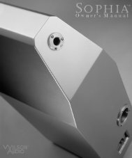
<strong>MAXX</strong> Se r i e s 3 Ow n e r ’ s Ma n u a lSection 7.2 – <strong>MAXX</strong> DimensionsFig u r e - 2670<strong>Wilson</strong> <strong>Audio</strong> Specialties
Section 8 – Propagation delay Tables
<strong>MAXX</strong> Se r i e s 3 Ow n e r ’ s Ma n u a l72<strong>Wilson</strong> <strong>Audio</strong> Specialties
S e c t i o n 8 – Pr o p a g a t i o n d e l a y Ta b l e sNumber 1: Lower Tweeter/Midrange Module Spike LengthListening DistanceEar Height 8' 9' 10' 11' 12' 14' 16' 18' 20' 22' 24' 26'48 No Spike No Spike No Spike No Spike No Spike No Spike No Spike No Spike No Spike No Spike No Spike No Spike46 No Spike No Spike No Spike No Spike No Spike No Spike No Spike No Spike No Spike No Spike No Spike No Spike44 2 2 No Spike No Spike No Spike No Spike No Spike No Spike No Spike No Spike No Spike No Spike42 3 2 2 2 No Spike No Spike No Spike No Spike No Spike No Spike No Spike No Spike40 3 3 3 3 2 2 No Spike No Spike No Spike No Spike No Spike No Spike38 3 3 3 3 3 3 2 2 No Spike No Spike No Spike No Spike36 3 3 3 3 3 3 3 2 2 No Spike No Spike No SpikeNumber 2: Lower Tweeter/Midrange Module Block PositionListening DistanceEar Height 8' 9' 10' 11' 12' 14' 16' 18' 20' 22' 24' 26'48 1 2 3 3.5 4 4.5 5.5 6 6.5 7 7 7.546 5 6 6 6.5 7 7.5 8.5 9 8 8.5 8.5 944 2.5 3.5 10 9.5 10 9.5 10 10.5 11 10 10 1042 3 6.5 6 6 11 12.5 12 12 12 11.5 11.5 1240 7.5 7 6 5.5 9 8.5 14.5 14 14 13 13 13.538 10.5 10 9 8 7.5 7 10.5 9.5 15.5 14.5 15 1536 15 13 12.5 11.5 10.5 10 8 11 10 16 16 15<strong>Wilson</strong> <strong>Audio</strong> Specialties73
<strong>MAXX</strong> Se r i e s 3 Ow n e r ’ s Ma n u a lNumber 3: Lower Tweeter/Midrange Module Block StepListening DistanceEar Height 8' 9' 10' 11' 12' 14' 16' 18' 20' 22' 24' 26'48 4 4 4 4 4 4 4 4 4 4 4 446 7 7 6 6 6 6 6 6 5 5 5 544 1 1 9 8 8 7 7 7 7 6 6 642 1 3 2 2 10 9 8 8 8 7 7 740 4 3 2 1 3 2 10 9 9 8 8 838 5 5 4 3 2 1 3 2 10 9 9 936 9 7 6 5 4 3 1 3 2 10 10 974<strong>Wilson</strong> <strong>Audio</strong> Specialties
N u m b e r 4: Up p e r Mi d r a n g e Mo d u l e Sp i k e Le n g t hNumber 4: Upper Midrange Module Spike LengthListening DistanceEar Height 8' 9' 10' 11' 12' 14' 16' 18' 20' 22' 24' 26'48 D D C C C C C B B B B B46 D D D D C C C C B B B B44 E E D D D C C C C B B B42 E E E D D D C C C C C B40 F F E E D D D C C C C C38 G F E E E D D D C C C C36 G F F F E E D D C C C CNumber 5: Upper Midrange Module Spike Detent LocationListening DistanceEar Height 8' 9' 10' 11' 12' 14' 16' 18' 20' 22' 24' 26'48 2 3 4 5 5 6 7 8 8 9 9 946 5 6 7 7 8 8 9 9 10 10 10 1044 9 9 10 10 10 10 11 11 11 11 11 1142 12 12 12 12 12 13 13 13 13 13 13 1340 15 15 15 15 15 15 14 14 14 14 14 1438 19 18 18 17 17 17 16 16 16 15 15 1536 22 21 21 20 20 19 18 17 17 17 16 16<strong>Wilson</strong> <strong>Audio</strong> Specialties75
<strong>MAXX</strong> Se r i e s 3 Ow n e r ’ s Ma n u a l76<strong>Wilson</strong> <strong>Audio</strong> Specialties
Section 9 – Warranty Section
<strong>MAXX</strong> Se r i e s 3 Ow n e r ’ s Ma n u a l78<strong>Wilson</strong> <strong>Audio</strong> Specialties
S e c t i o n 9.0 – Wa r r a n t y In f o r m a t i o nSection 9.0 – Warranty InformationLimited WarrantySubject to the conditions set forth herein, <strong>Wilson</strong> <strong>Audio</strong> warrants its loudspeakers tobe free of manufacturing defects in material and workmanship for the Warranty Period.The Warranty Period is a period of 90 days from the date of purchase by the originalpurchaser, or if both of the following two requirements are met, the Warranty Period is aperiod of five (5) years from the date of purchase by the original purchaser:Requirement No. 1. No later than 30 days after product delivery to thecustomer, the customer must have returned the Warranty RegistrationForm to <strong>Wilson</strong> <strong>Audio</strong>;Requirement No. 2. The product must have been professionally installed bythe <strong>Wilson</strong> <strong>Audio</strong> dealer that sold the product to the customer.FAILURE TO COMPLY WITH EITHER REQUIREMENT NO. 1 OR REQUIREMENT NO. 2WILL RESULT IN THE WARRANTY PERIOD BEING LIMITED TO A PERIOD OF 90 DAYSONLY.ConditionsThis Limited Warranty is also subject to the following conditions and limitations.The Limited Warranty is void and inapplicable if the product has been used or handledother than in accordance with the instructions in the owner’s manual, or has been abusedor misused, damaged by accident or neglect or in being transported, or if the product hasbeen tampered with or service or repair of the product has been attempted or performedby anyone other than <strong>Wilson</strong> <strong>Audio</strong>, an authorized <strong>Wilson</strong> <strong>Audio</strong> Dealer Technician ora service or repair center authorized by <strong>Wilson</strong> <strong>Audio</strong> to service or repair the product.Contact <strong>Wilson</strong> <strong>Audio</strong> at (801) 377-2233 for information on location of <strong>Wilson</strong> <strong>Audio</strong>Dealers and authorized service and repair centers. Most repairs can be made in the field.<strong>Wilson</strong> <strong>Audio</strong> Specialties79
<strong>MAXX</strong> Se r i e s 3 Ow n e r ’ s Ma n u a lIn instances where return to <strong>Wilson</strong> <strong>Audio</strong>’s factory is required, the dealer or customermust first obtain a return authorization. Purchaser must pay for shipping to <strong>Wilson</strong> <strong>Audio</strong>,and <strong>Wilson</strong> <strong>Audio</strong> will pay for shipping of its choice to return the product to purchaser.A RETURNED PRODUCT MUST BE ACCOMPANIED BY A WRITTEN DESCRIPTION OFTHE DEFECT. <strong>Wilson</strong> <strong>Audio</strong> reserves the right to modify the design of any product withoutobligation to purchasers of previously manufactured products and to change the prices orspecifications of any product without notice or obligation to any person.RemedyIn the event that the product fails to meet the above Limited Warranty and the conditionsset forth herein have been met, the purchaser’s sole remedy under this LimitedWarranty shall be to: (1) contact an authorized <strong>Wilson</strong> <strong>Audio</strong> Dealer within the WarrantyPeriod for service or repair of the product without charge for parts or labor, which serviceor repair, at the Dealer’s option, shall take place either at the location where theproduct is installed or at the Dealer’s place of business; or (2) if purchaser has timelysought service or repair and the product cannot be serviced or repaired by the Dealer,then purchaser may obtain a return authorization from <strong>Wilson</strong> <strong>Audio</strong> and at purchaser’sexpense return the product to <strong>Wilson</strong> <strong>Audio</strong> where the defect will be rectified withoutcharge for parts or labor.Warranty Limited to Original PurchaserThis Limited Warranty is for the sole benefit of the original purchaser of the coveredproduct and shall not be transferred to a subsequent purchaser of the product, unlessthe product is purchased by the subsequent purchaser from an authorized <strong>Wilson</strong> <strong>Audio</strong>Dealer who has certified the product in accordance with <strong>Wilson</strong> <strong>Audio</strong> standards andrequirements and the certification has been accepted by <strong>Wilson</strong> <strong>Audio</strong>, in which eventthe Limited Warranty for the product so purchased and certified shall expire at the endof the original Warranty Period applicable to the product.80<strong>Wilson</strong> <strong>Audio</strong> Specialties
S e c t i o n 9.0 – Wa r r a n t y In f o r m a t i o nDemonstration EquipmentEquipment, while used by an authorized dealer for demonstration purposes, is warrantedto be free of manufacturing defects in materials and workmanship for a periodof five (5) years from the date of shipment to the dealer. Demo equipment needing warrantyservice may be repaired on-site or, if necessary, correctly packed and returned to<strong>Wilson</strong> <strong>Audio</strong> by the dealer at dealer’s sole expense. <strong>Wilson</strong> <strong>Audio</strong> will pay return freightof its choice. A returned product must be accompanied by a written description of thedefect. Dealer owned demonstration equipment sold at retail within two (2) years of dateof shipment to the dealer is warranted to the first retail customer to be free of manufacturingdefects in materials and workmanship for the same time periods as if the producthad originally been bought for immediate resale to the retail customer. <strong>Wilson</strong> <strong>Audio</strong>products are warranted for a period of 90 days, unless extended to 5 years, as providedabove, by return and filing of completed Warranty Registration at <strong>Wilson</strong> <strong>Audio</strong> within30 days after product delivery to customer and the product was professionally installedby the <strong>Wilson</strong> <strong>Audio</strong> Dealer that sold the product to the customer.MiscellaneousALL EXPRESS AND IMPLIED WARRANTIES NOT PROVIDED FOR HEREIN AREHEREBY EXPRESSLY DISCLAIMED. ANY LEGALLY IMPOSED IMPLIED WARRANTIES RE-LATING TO THE PRODUCT SHALL BE LIMITED TO THE DURATION OF THIS LIMITEDWARRANTY. THIS LIMITED WARRANTY DOES NOT EXTEND TO ANY INCIDENTAL ORCONSEQUENTIAL COSTS OR DAMAGES TO THE PURCHASER.Some states do not allow limitations on how long an implied warranty lasts oran exclusion or limitation of incidental or consequential damages, so the above limitationsor exclusions may not apply to you. This Limited Warranty gives you specificlegal rights, and you may also have other rights, which vary from state to state.<strong>Wilson</strong> <strong>Audio</strong> Specialties81
<strong>MAXX</strong> Se r i e s 3 Ow n e r ’ s Ma n u a l82<strong>Wilson</strong> <strong>Audio</strong> Specialties