Alexia Owner's Manual - Wilson Audio
Alexia Owner's Manual - Wilson Audio
Alexia Owner's Manual - Wilson Audio
- No tags were found...

Create successful ePaper yourself
Turn your PDF publications into a flip-book with our unique Google optimized e-Paper software.
A l e x i a O w n e r ’ s M a n u a l1. Stand against the wall BEHIND the location where you intend to position<strong>Alexia</strong>. Speaking in a moderately loud voice and at a constant volume,project your voice out into the room. Your voice will have an overly heavy,“chesty” quality because of your proximity to the rear wall.2. While speaking, slowly move out into the room, progressing in a directionparallel to the sidewall. It is helpful to have another listener seated in thelistening position to assist you during this process. Listen to how your voice“frees up” from the added bass energy imparted by the rear wall boundary.Also notice that your voice is quite spatially diffuse (to your assistant, yourvoice will sound spatially large and difficult to localize) as you begin toease away from the rear wall.3. At some point during your progression forward into the room, you willobserve a sonic transition in your voice; it will sound more tonally correctand less spatially diffuse (your assistant can now precisely localize theexact origin of your voice). When you hear this transition, you have enteredthe inner edge of the Zone of Neutrality. Place a piece of tape on the floorto mark this location. Although it will vary from room to room, the zone inmost rooms begins between two and a half to three feet from the rear wall.4. Continue to walk slowly away from the rear wall. After some distance, usuallyone to two feet past the first piece of tape, you will begin to hear yourvoice lose focus and appear to reflect (echo) in front of you. This is causedby the return of the room’s boundary contribution; your voice is now interactingwith the opposite wall. At the point where you begin to hear thereflected sound of your voice, you have reached the inner edge of the Zoneof Neutrality. Place a piece of tape on the floor and mark this location. Thedistance between the “inner” and “outer” edge tape marks is usually betweeneight inches (for small, interactive rooms) and three feet (for large,more neutral rooms).5. Now position yourself against the side wall perpendicular to the intended10<strong>Wilson</strong> <strong>Audio</strong> Specialties
S e c t i o n 1 . 3 — R o o m R e f l e c t i o n sspeaker location. Stand between the two tape marks. Using the same procedureas above, begin moving into the room toward the opposite sidewall,progressing between the two pieces of tape. As above, listen for the pointin the room where your voice transitions from bass-heavy and diffuse toneutral. Mark this point with tape. Continue your progression until thereis an obvious interaction with the opposite wall in front of you and markthis point with tape. The four pieces of tape now form a rectangle that establishesthe Zone of Neutrality for the loudspeaker located on that side ofthe room. Using the four marks as your guide, tape an outline to define theboundaries of the rectangle.6. Repeat this process for each speaker location individually. These are yourZones of Neutrality, one for each channel.Theoretically, the Zone of Neutrality for any room runs like a path, parallel to thewalls all around the room. Adjacent to very large windows and open doors, the outeredge of the Zone of Neutrality moves closer to the wall and becomes wider. If you wereto extend the inner and outer boundaries of the Zone for the sidewalls and the frontwall (behind the speakers), they would intersect. After you complete this procedure forthe other loudspeaker, you will now have two rectangles, one on the floor on eitherside of the room.Section 1.3—Room ReflectionsNote: The following section contains general information on room acoustics and loudspeaker/roominteraction. The concepts outlined below are equally relevant whendealing with multi-channel audio or home theater. The careful application of theseconcepts, as you evaluate the acoustical characteristics of your own room configuration,will allow you to optimize the performance of <strong>Alexia</strong>.Slap EchoProbably the most obnoxious form of reflection is called “slap echo.” With slap-<strong>Wilson</strong> <strong>Audio</strong> Specialties11
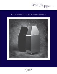
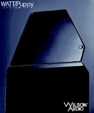
A l e x i a O w n e r ’ s M a n u a lecho, primarily midrange and high frequency sounds reflect off of two parallel hardsurfaces. The sound literally reverberates back and forth until it is finally dissipatedover time. You can test for slap echo in any room by clapping your hands sharply in themiddle of the room and listening for the characteristic sound of the echo in the midrange.Slap echo destroys the sound quality of a stereo system in two ways:• It adds harshness to the upper midrange and treble by storing time-domainsmearing energy.• It destroys the delicate phase relationships, which help to establish an accuratesoundstage.Slap echo (see Figure 1) is a common acoustical problem in the typical domesticFigure 1—Common Room Reflection Problems12<strong>Wilson</strong> <strong>Audio</strong> Specialties
S e c t i o n 1 . 3 — R o o m R e f l e c t i o n slistening room because most of these rooms have walls with a hard, reflective nature,only occasionally interrupted by curtains, wall art, or drapes. The best (but least practical)solution to eliminate slap echo is nonparallel walls. This is because, rather thansupport slap-echo, nonparallel walls allow the sound to diffuse. This approach can beaccounted for during the construction process. For existing rooms, slap echo can alsobe controlled entirely by the application of absorptive materials to the hard surfaces.These are absorptive materials that can be used to ameliorate slap echo:• Pinta Acoustic Sonex®• Air duct board• Cork panels• Large ceiling to floor drapes• Carpeting to wall surfacesIn many domestic listening environments, heavy stuffed furnishings reduce slapecho somewhat. Unfortunately, their effectiveness is not predictable. Diffusers aresometimes also used to very good subjective effect, particularly in quite large rooms.Sound absorbent materials such as described above will alter the tonal characteristicof the room by making it sound “deader,” less “bright and alive,” and “quieter.” Thesechanges usually make the room more pleasant for conversation, but sometimes renderit too dull in the high frequencies to be musically involving. Soundtrack effects will bemore localized. However, over-damping the room can render reproduced sound that islacking in musical involvement and “aliveness.”Diffusers, on the other hand, do not affect the tonal balance characteristic of theroom as much. Placed properly, diffusers create a smoother and more open sound.Some diffusers, due to their construction, create narrow midrange peaks and suck-outthe warmth region. Do not use diffusers on the wall behind the speakers or on the side-<strong>Wilson</strong> <strong>Audio</strong> Specialties13
A l e x i a O w n e r ’ s M a n u a lwalls directly beside the speakers. It is our experience that all of these room treatmentdevices should be used judiciously.Standing WavesAnother type of reflection phenomenon is “standing waves.” Standing waves causethe unnatural boosting or accentuation of certain frequencies, typically in the bass, tobe found at certain discreet locations in the room. These locations differ according toroom dimension and size. A room generating severe standing waves creates difficulty insetup. In these rooms, the speaker will sound radically different as it is moved around.The effects of standing waves on a loudspeaker’s performance are primarily in the areaslisted.• Tonal balance• Resolution of low-level detail• SoundstagingStanding waves are more difficult to correct than slap echo because they tend tooccur at a lower frequency. Absorbent materials, such as Pinta Acoustic Sonex®, areineffective at controlling reflections in the bass region. Moving speakers about slightlyin the room is, for most people, their only control over standing waves. Sometimes achange of placement of as little as two or three inches can dramatically alter the tonalbalance of a small system.Fortunately, minor low frequency standing waves are well controlled by positioningASC Tube Traps in the corners of the room. Very serious low frequency accentuationusually requires a custom-designed bass trap system.Low frequency standing waves can be particularly troublesome in rooms constructedof concrete or brick. These materials trap the bass in the room unless it is allowedto leak out of the room through windows and doors.14<strong>Wilson</strong> <strong>Audio</strong> Specialties
S e c t i o n 1 . 3 — R o o m R e f l e c t i o n sIn general, placement of the speaker in a corner will excite the maximal numberof standing waves in a room and is to be avoided for most direct radiator, full-rangeloudspeaker systems. Some benefit is achieved by placing the stereo pair of loudspeakersslightly asymmetrically in the listening room. This is so the standing waves causedby the distance between one speaker and its adjacent walls and floors are not the sameas the standing wave frequencies excited by the dimensions in the other channel.Comb Filter EffectThe “comb filter” effect is a special type of standing wave noticeable primarily athigher frequencies and shorter wavelengths.Acoustical comb filtering occurs when sound from a single source, such as a loudspeaker,is directed toward a microphone or listener from a distance. The first sound toreach the microphone is the direct sound, followed by a delayed, reflected sound. Atcertain frequencies, cancellation occurs because the reflected sound lags in phase relativeto the direct sound. This cancellation is most apparent where the two frequenciesare 180 degrees out of phase. Further, there is augmentation at other frequencies wherethe direct and the reflected sounds arrive in phase. Because it is a function of wavelength,the comb filter effect will notch out portions of the audio spectrum at linearlyspaced intervals. Subjectively, comb filter effect evidences itself as follows:• Added roughness to the sound• Reduction of harmonic richness• Smearing of lateral soundstage image focus and placementComb filter effects are often caused by side wall reflections. They are best controlledby very careful speaker placement and by the judicious placement of PintaAcoustic Sonex® or air duct panels applied to that part of the wall where the reflectionoccurs.<strong>Wilson</strong> <strong>Audio</strong> Specialties15
A l e x i a O w n e r ’ s M a n u a lSection 1.4—ResonancesResonance in listening rooms is generally caused by two sources:• Structures within the listening room.• The volume of air itself within the listening room.Structural ResonanceStructural resonances are familiar to most people as buzzes and rattles, but thistype of resonance usually only occurs at extremely high volume levels and is usuallymasked by the music. In many wood frame rooms the most common type of structuralresonance problem is “booming” of walls and floors. You can test for these very easilyby tapping the wall with the palm of your hand or stomping on the floor. Most roomsexhibit mid-bass “boom” when struck. The loudspeaker playing in the room also excitesthese resonances. To give you an idea of what the perfect wall would sound like,imagine rapping your hand against the side of a mountain. Structural wall resonancesgenerally occur in the low to mid-bass frequencies and add a false fullness to the tonalbalance. They, too, are more prominent at louder levels, but their contribution tothe sound of the speaker is more progressive. Rattling windows, picture frames, lampshades, etc., can generally be silenced with small pieces of caulk or with blocks of felt.However, short of actually adding additional layers of sheet rock to flimsy walls, thereis little that can be done to eliminate wall resonances.Volume ResonanceThe physical dimensions and volume of air in a room will also support standingwave modes and resonances at frequencies determined by the size of that room. Largerrooms will resonate at a lower frequency and have more complex (better) modal distributionsthan will smaller rooms. Volume resonances, wall panel resonances, and low16<strong>Wilson</strong> <strong>Audio</strong> Specialties
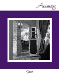
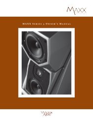
S e c t i o n 1 . 5 — Y o u r R o o mfrequency standing waves combine to form a low frequency coloration in the sound. Atits worst, it is a grossly exaggerated fullness, which tends to obscure detail and distortthe natural tonal balance of the speaker system.Occasionally, however, there is just enough resonance to give a little addedwarmth to the sound—an addition some listeners prefer. Careful placement of loudspeakersin the room can dramatically reduce the speakers’ destructive interactionwith low frequency modes. ASC Tube Traps are effective in reducing some of this lowfrequency room coloration. Custom designed bass traps, such as perforated Helmholtzresonators, provide the greatest degree of low frequency control.Section 1.5—Your RoomRoom ShapesStanding waves are pressure waves propagated by the interaction of sound and opposingparallel walls. This interaction creates patterns of low and high acoustical pressurezones that accentuate and attenuate particular frequencies. Those frequencies aredependent on room size and dimension.There are three basic shapes for most rooms: square, rectangular, and L-shaped(see Figure 2).A perfectly square room is the most difficult room in which to set up speakers.By virtue of its shape, a square room is the perfect medium for building and sustainingstanding waves. These rooms heavily influence the music played by loudspeakers,greatly diminishing the listening experience.Long, narrow, rectangular rooms also pose their own special acoustical problemsfor speaker setup. They have the ability to create several standing wave nodes, whichwill have different standing wave frequency exaggerations depending on where you<strong>Wilson</strong> <strong>Audio</strong> Specialties17
A l e x i a O w n e r ’ s M a n u a lare sitting. Additionally, these longrooms are often quite lean in thebass near the center of the room.Rectangular rooms are still preferredto square rooms because, by havingtwo sets of dissimilar length walls,standing waves are not as stronglyreinforced and will dissipate morequickly than in a square room. Inthese rooms, the preferred speakerposition for spatial placement andmidrange resolution would be onthe longer walls. Bass responsewould be reinforced by speakerplacement on the short walls.In many cases, L-shaped rooms(See Figure 2) offer the best environmentfor speaker setup. Ideally,speakers should be set up along theprimary (longest) leg of the room.They should fire from the end of theleg (short wall) toward the L, or theyshould be along the longest wall.In this way, both speakers are firingthe same distance to the back wall.The asymmetry of the walls in L-Figure 2—Possible Loudspeaker Placement withinVarious Room Shapes18<strong>Wilson</strong> <strong>Audio</strong> Specialties
S e c t i o n 1 . 5 — Y o u r R o o mshaped rooms resists the buildup of standing waves (see Figure 2).<strong>Alexia</strong> In A Dedicated Home TheaterHome theaters can be organized many different ways. Some use rows of couches.Others use rows of multiple chairs.In addition to watching movies, most users want to listen to two-channel music atthe highest quality possible. It is desirable, therefore, to choose a single optimum seatingposition in a home theater and build the rest of the seating positions around thisposition.If your optimum position is located on a couch, you should center the loudspeakerson the center position of the couch.If the seating area consists of multiple rows of chairs, the second row should beoptimized for the best sound quality. Odd numbers of chairs arranged in rows workbest as this will allow a single chair to be positioned in the center. This approach willalso provide the best overall sound for the greatest number of seats.Speaker Placement Versus Listening PositionThe location of your listening position is as important as the careful setup of <strong>Alexia</strong>speakers. The listening position should ideally be no more than 1.1 to 1.25 timesthe distance between the tweeters on each speaker. Therefore, in a long, rectangularroom of 12’ x 18’, if the speaker tweeters are going to be 9’ apart, you should be sitting9’11’’ to 11’3’’ from the speaker. This would be more than halfway down the long axisof the room.Many people place the speakers on one end and sit at the other end of the room.This approach will not yield the finest sound. Carefully consider your listening position.Our experience has shown that any listening position that places your head closer<strong>Wilson</strong> <strong>Audio</strong> Specialties19
A l e x i a O w n e r ’ s M a n u a lthan 14” from a room boundary will diminish the sonic results of your listening. Sittingdirectly in the center of the room will noticeably reduce the perception of low frequencies.Decide where you want your favorite listening position to be. Please rememberthat <strong>Alexia</strong> will fill almost any room with the most beautiful sound available. Becausethe propagation delay is adjustable on the <strong>Alexia</strong>, if you take care in placing your newspeakers, you will optimize <strong>Alexia</strong>’s performance in your room.Speaker OrientationSpeaker placement and orientation are two of the most important considerationsin obtaining superior sound. The first thing you need to do is eliminate the sidewalls asa sonic influence in your system. Speakers placed too close to the sidewalls will sufferfrom a strong primary reflection. This can cause out-of-phase cancellations, or combfiltering, which will cancel some frequencies and change the tonal balance of the music.The <strong>Wilson</strong> <strong>Audio</strong> Setup Procedure (Section 1.2) is the best method with which toposition your loudspeakers. Start with the speakers about 18” from each wall and, ifyou need to move them relative to the side wall, move them away from the wall, notcloser.A very important aspect of speaker placement is how far from the back wall toplace the speakers. The closer a loudspeaker is to the back wall, the more pronouncedthe low bass energy and centering of the image will be. However, this comes at a definitereduction in stage size and bloom as well as a deterioration of upper bass quality.You must find the proper balance of these two factors, but remember, if you are partialto bass response or air and bloom, do not overcompensate your adjustments to maximizethese effects. Overcompensated systems are sometimes pleasing in the short-term,but long-term satisfaction is always achieved through proper balance.20<strong>Wilson</strong> <strong>Audio</strong> Specialties
S e c t i o n 1 . 5 — Y o u r R o o mThe <strong>Alexia</strong> is designed for maximum phase coherence and pulse replication accuracywhen each speaker is aimed directly at the listener or microphone. Thus, <strong>Alexia</strong>should be “toed in.” In other words, the listener, when seated in the listening positionlooking forward with his/her head in a rested position, should just barely see throughthe gap created by the woofer blade and the lower side of the Upper Array. <strong>Alexia</strong>. Toeingin the speakers provides meaningful improvements in resolution of low-level detailin the midrange as well as appreciable improvements in soundstaging performance.SummaryIn summary, for optimal tonal balance accuracy, resolution of low level detail, andsoundstaging performance, the <strong>Alexia</strong> should be positioned as outlined in this section.Ideally, the speakers should not be positioned too far from the listener if maximumresolution of low-level detail is required. If possible, the speakers should be positionedout into the room, slightly asymmetrically vis-a-vis the side and rear walls. The speakersshould be “toed in” toward the listener, preferably so that the listener, at his seatedposition, can barely see the surface of the inner side of the <strong>Alexia</strong> as he/she faces thespeaker. It is recommended that a distance of two to three feet, and possibly more, bemaintained between the <strong>Alexia</strong> and the rear walls and that a distance of at least twofeet be maintained between the front panel of the <strong>Alexia</strong> and reflective side walls. Dependingon the room, judicious use of sound absorbent materials will reduce the spacerequirement.By following the guidelines in this manual, your new <strong>Alexia</strong> loudspeakers can provideyou with a lifetime of pure music reproduction.<strong>Wilson</strong> <strong>Audio</strong> Specialties21
<strong>Wilson</strong> <strong>Audio</strong> Specialties
Section 2—Uncrating <strong>Alexia</strong>
<strong>Wilson</strong> <strong>Audio</strong> Specialties
S e c t i o n 2 . 1 — U n c r a t i n g t h e A l e x i aNote: You will have two Upper Array enclosures as well as two Woofer Module enclosuresto unpack. The two modules will need to be separated into right and left channels.Clear out two spaces, one for your left and one for your right channels. Placethe ODD numbered modules in the LEFT channel section and the EVEN in the RIGHTchannel position.Section 2.1—Uncrating the <strong>Alexia</strong>Initial CheckThe <strong>Alexia</strong> is shipped in three wooden crates. Upon receiving these crates, pleasecheck their condition. If any of the crates are damaged, please report it to the shippingcompany immediately for insurance verification.The following items are recommended for this procedure:• Electric Screwdriver• Phillips head drive bit• Masking tape (for use in speaker setup)Uncrating the Woofer ModuleA minimum of two strong adults is required to set up the <strong>Alexia</strong>. Locate the twolargest crates labeled “Woofer Module.” These contain the woofer enclosures and arethe first components of the system to unpack.1. With the crate lid facing up, unscrew the wood screws securing the lid. Removethe lid.2. Carefully rotate the crate upright so that the Woofer Module is now vertical.With the Woofer Module’s bottom toward the floor, reach in and gentlyroll the Woofer Module out of the crate, carefully, so as not to hit theWoofer Module on the crate and scratch the paint.3. Place the Woofer Module with an odd serial number on the left side of the<strong>Wilson</strong> <strong>Audio</strong> Specialties25
A l e x i a O w n e r ’ s M a n u a lroom and the Woofer Module with an even serial number on the right sideof the room.Note: These two woofer enclosures are very heavy and care should be taken to preventinjury. Roll the Woofer Module with drivers facing forward for the best stability.Uncrating the Upper ArrayThe Upper Arrays are contained in a single crate. Unpack the modules using thefollowing procedure:1. With the crate lid facing up, unscrew the wood screws securing the lid. Removethe lid.2. The Upper Array crate contains the owner’s manual and tool kit. Removethese.3. Make sure the thumb bolt that secures the Tweeter is tight before moving.4. When removing the upper modules, take care so as not to hit the moduleson the crate and scratch the paint. Using the small shelf on the rear of themodule, tilt it so there is access to the bottom side. Slide the other handunder the Upper Array for support, and carefully lift the enclosure out ofthe crate.5. The cloth grilles are attached to the modules. Detach the grilles from themodule and remove the protective plastic covering the grill.6. Place the Upper Array with an odd serial number on the left side of theroom and the Upper Array with an even serial number on the right side ofthe room.Section 2.2—Crate Content ChecklistNow that you have unpacked your <strong>Alexia</strong>s, you can inventory all the additional26<strong>Wilson</strong> <strong>Audio</strong> Specialties
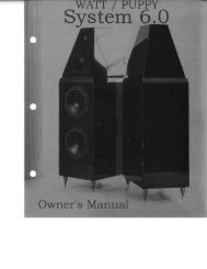
S e c t i o n 2 . 2 — C r a t e C o n t e n t C h e c k l i s titems in the crates.1 - Owner’s <strong>Manual</strong>1 - Warranty Registration2 - sets of three grills, Pin Style Grilles (1 set per enclosure)4 - “AA” Spikes2 - #2 Spikes2 - #3 Spikes2 - #4 Spikes1 - 1/2” Nut Driver1 - Polishing Cloth8 - Woofer Module Spike assembly (with conical diode)8 - Aluminum Disk Spike Floor Protectors1 - Allen Driver Handle1 - 3/32” Allen Insert1 - 5/32 Allen Insert1 - 1/8” Allen Insert1 - 7/16” Combination Wrench1 - 9/16” Combination Wrench1 - Caster Wrench1 - 3/8” Allen Wrench1 - 3/16” L-shaped Allen Wrench2 - 9.0 Ohm Resistors2 - 5.1 Ohm Resistors<strong>Wilson</strong> <strong>Audio</strong> Specialties27
A l e x i a O w n e r ’ s M a n u a lNote: After set up of the system, keep the shipping crates in case of futureshipping needs.<strong>Alexia</strong> Tool KitDiodeResistorsAluminum SpikePads7/16" and 9/16"WrenchAllen DriverCastor Wrench1/2" Nut Driver3/32", 5/32", and 1/8"Allen Inserts3/8" DriverAllen Wrench<strong>Alexia</strong> Spike KitResistorsPolishing Cloth1 1/2" Set Screws#3 SpikeSpike with Nut"AA" Spike #2 Spike #4 SpikeFigure 3—Tool Kits28<strong>Wilson</strong> <strong>Audio</strong> Specialties
Section 3—Initial Setup
<strong>Wilson</strong> <strong>Audio</strong> Specialties
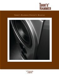
S e c t i o n 3 . 1 — I n i t i a l A s s e m b l yNote: Before setting up the <strong>Alexia</strong>, study carefully Section 1, “In Your Room.” It providesvaluable information on determining the ideal room location for your speakers.Section 3.1—Initial AssemblyPreparationYou will need the following items:• Supplied hardware kit• Tape measure• Propagation Delay Correction Tables (Section 8)• Known listening position• Masking TapeTake a moment to familiarize yourself with the top of the Woofer Module. A completeset of Propagation DelayCorrection Tables is located inSection 8.Upper Array AssemblyThe Upper Array uses thecombination of a captive spikeor the addition of one of three“AA” Spikesdifferent length accessory spikesinstalled into the bottom of itsenclosure. The spikes rotate theUpper Array to a scribed positionas a part of the <strong>Alexia</strong>’s propaga-Figure 4—Install “AA” spikes in front. Install appropriatealignment spike in the rear of Upper Array.<strong>Wilson</strong> <strong>Audio</strong> Specialties31
A l e x i a O w n e r ’ s M a n u a ltion delay adjustment. The spike also provides proper coupling of the Upper Array tothe Woofer Module. Shorter “AA” spikes are always installed in the front two positions(the threaded holes located near the bottom front of the enclosure). The spike-type isstamped in the round top of the spike. The two “AA” spikes screw into the Upper Arrayas shown in Figure 4. The spikes should be screwed in all the way, until they are handtight. Do not over tighten spikes.Section 3.2—<strong>Alexia</strong> Propagation Delay AdjustmentRoom SetupAs indicated in Figure6, the <strong>Alexia</strong> system allowsfor different listeningdistances (away from thespeakers) and listening earheights (measured distancesfrom the floor to yourear). For each distance/earheight combination there isa unique alignment geometry.To make correct inhomeset up of the <strong>Alexia</strong>possible without testUpper Array SpikePlacement GuidePainted Inner Edge andtop of Woofer ModuleForward/BackNumbered TrackRotation Ladderequipment, <strong>Wilson</strong> <strong>Audio</strong>has measured the correctFigure 5—Top of the Woofer Module, with spike guides andrear spike receptacle.32<strong>Wilson</strong> <strong>Audio</strong> Specialties
S e c t i o n 3 . 2 — A l e x i a P r o p a g at i o n D e l ay A d j u s t m e n tgeometric time domain alignment for different distance/ear height combinations. Thisinformation is provided in the Propagation delay Tables in Section 8. By measuring theear height and the distance from the speaker to the listening position, you will be ableto align the system for your listening position.Alignment ProcedureLocate the Alignment tables in Section 8. These tables contain critical informationthat will guide you to position the Upper Arrays for optimized propagation delay adjustment.The rear of the Upper Array assembly rests on a specific step in the AlignmentBlock. The alignment tables also contains information on the front-to-back alignment ofthe Upper Array. The position of the Upper Array is facilitated by the Alignment BlockEar Height (Measured from Floor)Listening Distance (Measured on Floor)Figure 6—Measure Listening Distance and Ear Height.<strong>Wilson</strong> <strong>Audio</strong> Specialties33
A l e x i a O w n e r ’ s M a n u a lsteps (rotation) as well as frontto-back—theposition of theAlignment Block. The positionis designated by the engravednumbers in the Alignment Blockmounting plate. Position theAlignment Block by aligningthe rear of the Alignment Blockto the number engraved on theplate as indicated in the chartin Section 8. There are also fourspike configurations, the useof which are determined by thedistance/ear relationship of theFigure 7—Slide the Alignment Block to Its Proper PositionAlign the rear of the blockto the correct numberinstallation. The three configurations are: no spike, or either a number 1, 2, or 3 spike.The table in Section 8 also contains information on the appropriate length spike to beused in the rear of the Upper Array.The Tweeter module’s upper plate features detents that correspond to a spike builtinto the front of the upper cross member located above the tweeter module (see Figure7), the specific location of which determines the propagation delay position ofthe tweeter module within the Upper Array. The alignment plate contains numberedindents. The alignment tables in Section 8 contain the information for positioning thetweeter module in the array, determined by the indent in which the cross member’sspike rests.Determine the alignment of each Upper Array and the Tweeter Module as follows:1. Repeat each step of this procedure on the left and right channels simultane-34<strong>Wilson</strong> <strong>Audio</strong> Specialties
S e c t i o n 3 . 2 — A l e x i a P r o p a g at i o n D e l ay A d j u s t m e n tously.2. Remove the Propagation Delay Tables from Section 8 in this booklet andplace them close by for easy reference. Propagation Delay Tables are alsoavailable on <strong>Wilson</strong> <strong>Audio</strong> APP, which is available on iTunes.3. Make sure that you are in your intended listening position.4. While sitting, have someone measure your ear height from the floor directlybelow your ear canal. You should be relaxed in your chair, as you would bewhen listening to music (see Figure 7).5. Now measure the distance (on the floor) from the point on the floor belowyour ear to the base of the loudspeaker, as shown in Figure 6.6. Refer to the Propagation Delay Tables (Section 8) and locate the correspondingear height for each module. There are four charts for the UpperArray. The first: “<strong>Alexia</strong> Upper Array Spike Length” is a table determiningthe rear spikelength. The secondis the table:“<strong>Alexia</strong> UpperArray AlignmentBlock Position”determining theblocks front-tobacklocation (seeFigure 7). The thirdtable: “<strong>Alexia</strong> UpperArray AlignmentBlock Step”specifies the stepon which the rearspike will rest(see Figure 7). TheFigure 8—Position Rear Spike of the Upper Array intothe Proper Block Step<strong>Wilson</strong> <strong>Audio</strong> Specialties35
A l e x i a O w n e r ’ s M a n u a lfourth table: “Tweeter Module Detent Position” specifies the position of thebridge spike into the detent on the top of the tweeter module (see Figure 7).7. Make a mark on the chart Number 1 “<strong>Alexia</strong> Upper Array Spike Length”indicating the proper rear spike for this module as determined by the earheight and distance from listening position.Note: The shortest spikes (labeled AA) are always used at the front of the Upper Array.8. Make a mark on the second chart labeled “<strong>Alexia</strong> Upper Array AlignmentBlock Step Position” indicating the block location for that module. Set thisinformation aside as you will refer to it in the next section. (See Figure 7.)9. Make a mark on the third chart labeled “<strong>Alexia</strong> Upper Array AlignmentBlock Step” indicating Upper Array spike’s resting position on the alignmentblock. Set this information aside as you will refer to it in the next section.(See Figure 7.)10. Refer to Table Number4 labeled “<strong>Alexia</strong>Tweeter Detent Location.”This table indicatesthe detent locationin which the crossmember spike rests(see Figure 9).Section 3.3—Mounting theUpper ArrayMaterials Required:• Correct spikes for themodules.Figure 9—Tweeter Bridge Spike Position in thePropagation Delay Detent36<strong>Wilson</strong> <strong>Audio</strong> Specialties
S e c t i o n 3 . 3 — M o u n t i n g t h e U p p e r A r r a y• The pages from Section 8 front-to-back location of each module, along withthe use of the proper length of rear spike of the upper modules. Refer to the<strong>Alexia</strong> Propagation delay Tables and the procedure in the previous sectionto determine the correct Aspherical Propagation delay spikes as necessary,Figure 10—Slide the Upper Array’s front spikes along the guides in the top of the WooferModule, keeping the rear of the Upper Array elevated to avoid scratching the Woofer Module.<strong>Wilson</strong> <strong>Audio</strong> Specialties37
A l e x i a O w n e r ’ s M a n u a lthe Alignment Block position, and the proper step location of the step.Install the Upper Array As Follows:1. Install the front pair of short (AA length) spikes into the bottom of eachmodule (see Figure 7).2. Refer to the table labeled “<strong>Alexia</strong> Upper Array Spike Length” and install theappropriate rear spike if necessary.3. Refer to table labeled “<strong>Alexia</strong> Upper Array Alignment Block Step Position.”Using the rear edge of the Alignment Block as the guide, align the block tothe proper front-to-back setting for the Upper Array. (Figure 7). Once theblock is in its proper position, lock it down using the 3/8” Allen wrench.4. Refer to the table labeled “<strong>Alexia</strong> Upper Array Alignment Block Step”Block Position table. With the front spikes pointing down, carefully lowerthe Upper Array between the alignment wings and set it on top of the wooferenclosure(see Figure10). Thereare alignmenttracks thataccommodatethe spikesand guide theUpper Arraytoward itsappropriateresting place.Rest the rearspike on theappropriatestep on theladder.Tighten the thumb bolt tosecure Tweeter ModuleFigure 11—Tighten thumb bolt to secure the Tweeter Module.38<strong>Wilson</strong> <strong>Audio</strong> Specialties
S e c t i o n 3 . 4 — T w e e t e r M o d u l e P r o p a g a t i o n D e l a yNOTE: Take caution not to scratch the painted surface with the alignment spike as youinstall the Upper Array.Section 3.4—Tweeter Module Propagation DelayRefer to Table Number 4 labeled “<strong>Alexia</strong> Tweeter Spike Detent Location.” Loosenthe oval bolt on the rear of the tweeter module enough that it can freely move front-toback.5. Locate the number onthe plate on the upperplane of the tweeterthat corresponds tothe detent indicatedin the table (see Figure9).6. Slide the tweeter suchthat the downwardpointing spike of theArray bridge alignswith the appropriatenumbered detent.7. Retighten the ovalthumb bolt, ensuring that the spike rests properly in its appropriate detent(see Figures 9 and 11).Figure 12—Connect the umbilicals to the two Upper Arrayinputs, observing correct polarity.Section 3.5—Umbilical ConnectionsThe correct connection of the two umbilicals to the Upper Array is as follows (seeFigure 12):1. Locate the connection labeled “Mid Frequency.”<strong>Wilson</strong> <strong>Audio</strong> Specialties39
2. Locate the cable marked “MID FREQ.” This cable exits the top of theWoofer Module just below the appropriate connector. Connect the RED lugof the cable to the RED (positive) terminal on the terminal labeled “Midrange.”Connect the black lug of the cable to the BLACK (negative) terminal.3. Locate the cable marked “High Freq.” Connect the RED lug to the REDterminal on the connection labeled “High Frequency” on the Upper Array.Connect the black lug of the cable to the BLACK (negative) terminal.Note: Please ensure that you do not invert the polarity of the umbilicals in the <strong>Alexia</strong>.Such an inversion will produce entertaining ambient effects, but destroys the linearityand harmonic structure of the system.<strong>Wilson</strong> <strong>Audio</strong> Specialties
Section 4—Final Setup
<strong>Wilson</strong> <strong>Audio</strong> Specialties
S e c t i o n 4 . 1 — S p i k i n g t h e A l e x i aSection 4.1—Spiking the <strong>Alexia</strong>Your dealer is trained in the art and science of the <strong>Wilson</strong> <strong>Audio</strong> Setup Procedure(WASP) outlined in Section 1.1. Before the spike/diode assemblies are attached to thebottom of <strong>Alexia</strong>, the set up and fine tuning of your loudspeaker should be completed.Before spiking <strong>Alexia</strong>, use masking tape to carefully mark their location.Spike Assembly1. Remove the mechanical diodes and move the nut to about two threads fromthe point. This will allow for greater movement when leveling the loudspeakersystem.2. Screw the spikes into the diode until the nut is against the diode. Be carefulthat the nut does not turn while inserting and threading spikes into thediode.3. Place the set screw into the other end of the diode with the Allen headtoward the spike. This will ensure that if for any reason you have to removeyour <strong>Alexia</strong> spikes, you will be able to withdraw the set screw safely usingthe supplied Allen wrench. Screw the set screw into the diode until it meetsthe spike (see Figure 13).4. Assemble the rest of the spikes/diodes5. Place the assemblies out of the traffic pattern until they are needed duringthe installation.Note: Do not tighten these assembled spikes. You will need to unscrew them whenyou level the <strong>Alexia</strong>. This will ensure that if for any reason you have to remove <strong>Alexia</strong>spikes, you will be able to withdraw the set screw using the supplied Allen wrench.Installation Procedure6. Take care to mark the exact location of the <strong>Alexia</strong>s with masking tape toensure the speakers can be returned to their set up position.<strong>Wilson</strong> <strong>Audio</strong> Specialties43
A l e x i a O w n e r ’ s M a n u a l7. Remove the Upper Array from the Woofer Module.8. Carefully lay the Woofer Module on its side.9. Using the caster wrench, remove the casters.10. Insert the diode/spike assemblies into the four holes located on the bottomof each Woofer Module. Tighten until the top surface of the Woofer ModuleDiode touches the bottom surface of the “X” material plate.11. Taking care observe the location of the woofer module to the masking tapemarking the precise location of <strong>Alexia</strong>’s position, return the module to anupright position.12. Re-install the Upper Array atop the Woofer Module.Figure 13—Spike/Diode Assembly44<strong>Wilson</strong> <strong>Audio</strong> Specialties
S e c t i o n 4 . 2 — L e v e l i n g t h e A l e x i aNote: The spike receptaclesare tapped directly into the“X” material plate on the bottomof the Woofer Module. Bevery careful NOT TO CROSSTHREAD the spikes (see Figure14).Section 4.2—Leveling the<strong>Alexia</strong>1. Place a level onthe left to rightoriented axis inthe flat area atopthe woofer behindthe Upper Array. Ifit is level, move tothe next step.2. You may rotate thespike tips in placeby using a vice-grip or toothed pliers.Figure 14—Install the assembled Woofer Module Spikesby removing the Upper Array and turning the WooferModule on its side.3. Lengthen the appropriate spike or spikes (not the Woofer Module Spike diodeon the set screw) on the lower side until the <strong>Alexia</strong> is level.4. If the speaker is leaning to the left, lengthen both Woofer Module spikes onthe right hand side of the speaker. If the speaker is leaning right, lengthenthe left hand spikes. Lengthen the spikes incrementally, checking and recheckingthe level until the <strong>Alexia</strong> is level left to right.5. Place a level on the front to back oriented axis. If it is level, then <strong>Alexia</strong>is level. If the <strong>Alexia</strong> is leaning one way or the other, following the same<strong>Wilson</strong> <strong>Audio</strong> Specialties45
A l e x i a O w n e r ’ s M a n u a lprocess as above, lengthen the appropriate spikes on the front or rear of theWoofer Module until the <strong>Alexia</strong> is level.6. To find out which spike to lower, grasp the <strong>Alexia</strong> channel and gently rockit back and forth. This will identify the spike that is out of level from theother three. If there is movement, lengthen the appropriate spike until the<strong>Alexia</strong> sits solidly on the floor. Make sure the spike is penetrating the carpetsurface and is resting on the solid floor beneath. Alternatively, if isdesirable to protect the surface beneath the spike, the aluminum spike diskscan be installed. There is a conical detent in the disk in which the spikerests.7. Once all adjustments have been made, with the 9/16” wrench provided,tighten the nut on the spike to the diode. DO NOT OVERTIGHTEN! “Snug”is tight enough.Section 4.3—Removing the Protective FilmTo protect the finish of the <strong>Alexia</strong> during final manufacture, shipment, and setupin your listening room, we have applied a removable layer of protective film over thefinish. We recommend that this film be left in place until the speakers are in their finallocation in your listening room. Once you have determined their final position, removethe film by following this procedure:1. Ensure the speaker surface is room temperature before removing the protectivefilm.Note: Removing the protective film when the speaker surface is cold can damage thepaint surface.2. Slowly remove the film from the top down, large sections at a time, gentlypulling the film downward and outward.Note: Tearing the film aggressively can damage the paint.46<strong>Wilson</strong> <strong>Audio</strong> Specialties
S e c t i o n 4 . 4 — R e s i s t o r s3. Take care in removing the protectivefilm near edges and corners to preventpaint damage in these areas.4. The protective film should not be lefton the painted surface for extendedperiods of time nor exposed to heatsources and direct sunlight.Section 4.4—ResistorsBy removing the large aluminum back coveron the rear of the woofer module of your <strong>Alexia</strong>s,you may gain access to the resistor plate (see Figures15 and 16). These resistors serve several functions.Note: Only <strong>Wilson</strong> <strong>Audio</strong> replacement resistorsshould be used in your <strong>Alexia</strong>s. Changing the valueor brand of resistor will have a deleterious affecton the sonic performance of your loudspeakersand will void your <strong>Wilson</strong> <strong>Audio</strong> Warranty.Figure 15—The resistors are locatedunder the plate on the rearof the woofer enclosure.Midrange and Tweeter ResistorsThe Midrange Level, which consists of a 2.55 ohm (2x5.1 in parallel) (See Figure16) resistor assembly for the mid, and Tweeter Level, which consists of 4.5 ohm (2x9.0in parallel) resistor assembly for the tweeter, resistors provide precise level matchingfor the midrange and tweeter drivers correspondingly. The resistors also act as ultrahigh quality fuses which open before a driver can be damaged by excess power. SeeSection 6.0 for details in replacing these resistors in the event one of these resistors isdamaged.<strong>Wilson</strong> <strong>Audio</strong> Specialties47
A l e x i a O w n e r ’ s M a n u a lWoofer Damping ResistorThere is a 18.6 ohm barrel resistor for woofer level. The 3.56 ohm Q resistor affectsWoofer Damping, which in turn affects the way the <strong>Alexia</strong>’s woofers couple to theamplifier. Both of these resistors are pre-installed in the base of the Bass Module andshould not be changed by the end user.Figure 16—Mid & Tweeter Resistor are attached to heatsinks with Allen hardware.48<strong>Wilson</strong> <strong>Audio</strong> Specialties
Section 5—Care of Your <strong>Alexia</strong>
<strong>Wilson</strong> <strong>Audio</strong> Specialties
S e c t i o n 5 . 1 — C a r e o f t h e F i n i s hSection 5.1—Care of the FinishThe <strong>Alexia</strong> loudspeakers are handpainted with <strong>Wilson</strong>Gloss paint andhand polished to a high luster. While thefinish seems quite dry to the touch, finalcuring and complete hardening takesplace over a period of several weeks.Dusting the <strong>Alexia</strong>It is important that the delicatepaint finish of the <strong>Alexia</strong> be dusted carefullywith the provided dust cloth. Werecommend that the following procedurebe observed when dusting the speakers:• Blow off all loose dust.• Using the special dust clothas a brush, gently whisk off any remaining loose dust.• Shake out the dust cloth.• Dust the finish, using linear motions in one direction parallel to the floor.Avoid using circular or vertical motions.Because the paint requires a period of several weeks to fully cure, we recommendthat no cleaning fluids, such as glass cleaners, be used during this initial period oftime. When the paint is fully cured, heavy fingerprints and other minor smudges maybe removed with a glass cleaner. Always use the dust cloth. Stronger solvents are notrecommended under any circumstances. Consult your dealer for further information ifrequired. To maintain the high luster of the finish, periodic polishing may be desired.<strong>Wilson</strong> <strong>Audio</strong> Specialties51
A l e x i a O w n e r ’ s M a n u a lWe recommend a nonabrasive carnauba-based wax and a soft cloth.Care of the GrillesPeriodically, you will want to clean the <strong>Alexia</strong>’s grilles. This is best done by usingthe round brush attachment on a vacuum cleaner hose. Gently vacuum the front surfaceof the grille. Be careful not to apply too much pressure. Do not use a hard plasticattachment against the grille. The grille cloth is stretched tightly over the grille frame.Too much pressure or use of a hard plastic attachment could cause the grille materialto tear, especially in the corners.Often <strong>Wilson</strong> speaker owners desire to change the look of their listening room bychanging the color of their speaker grilles. In addition to basic black, <strong>Wilson</strong> <strong>Audio</strong>offers a variety of grille colors to match most <strong>Wilson</strong>Gloss finishes. Contact your localdealer for grille cloth samples or to order replacement grilles for <strong>Alexia</strong>.Break-in PeriodAll audio equipment will sound best after its components have been broken in forsome period of use. <strong>Wilson</strong> <strong>Audio</strong> breaks in all drivers for approximately 12 hours. Alldrivers are then tested, calibrated, and matched for their acoustical properties. In yourlistening room, expect 25 to 50 percent of break-in to be complete after two hours ofplaying music at normal listening levels. Ninety percent of break-in is complete after24 hours of playing. Playing a CD on repeat overnight can accomplish this task quickly.<strong>Wilson</strong> <strong>Audio</strong> recommends chamber music for this task.Section 5.2—Enclosure TechnologyMaterials<strong>Wilson</strong> <strong>Audio</strong> continues to conduct many hours of research on the impact of ma-52<strong>Wilson</strong> <strong>Audio</strong> Specialties
S e c t i o n 5 . 3 — D e p t h o f D e s i g nterials on speaker enclosure performance. Through this effort, <strong>Wilson</strong> pioneered theuse of non-resonant materials, first with the use of mineral-filled acrylic in the WAMMand WATT and continuing with the further development of proprietary materials for X-1Grand SLAMM and the original WATT/Puppy. Even the best materials are not suited toall aspects of enclosure construction. Therefore, like all <strong>Wilson</strong> loudspeakers, the <strong>Alexia</strong>is constructed of several exotic materials chosen for their specific performance attributesrelevant to different portions of the enclosure.<strong>Alexia</strong> is constructed using utlra-low-resonant, high-density, composites which arethen cross-braced to further reduce cabinet resonance. Each of these composites meetsand exceeds the highest of ANSI test standards for its use, while offering very tight tolerances,high hardness, uniform density, and dimensional stability.Adhesive<strong>Wilson</strong> <strong>Audio</strong> has conducted exhaustive research into the best adhesives to permanentlybond our speaker enclosures. This is often an overlooked element crucial to theproper performance of a loudspeaker. Correct modulus of elasticity, coefficient of thermalexpansion, and natural frequency response are just a few of the important elementsof adhesives.A highly cross-linked, thermoset adhesive is used for the construction of the enclosure.It was also chosen for its excellent bond strength, solvent resistance, hardness,and optimum vibrational characteristics.Section 5.3—Depth of Design<strong>Alexia</strong>’s compellingly authentic performance and lasting value are achievedthrough careful implementation of cutting edge design and engineering and then executedusing the highest performance materials. <strong>Wilson</strong> <strong>Audio</strong>’s use of proprietary<strong>Wilson</strong> <strong>Audio</strong> Specialties53
A l e x i a O w n e r ’ s M a n u a lenclosure materials and adhesives areemployed to achieve truly exceptionalspeaker cabinet performance. The use ofthese materials in <strong>Alexia</strong> results in an enclosurethat is inherently inert and nonresonant.All of these structural aspectsare combined, allowing <strong>Wilson</strong> <strong>Audio</strong>to deliver a product that maintains thestrictest structural tolerances, durability,and reliability. This also means that the<strong>Alexia</strong> will have consistent, repeatableperformance, unaffected by the climaticconditions, anywhere in the world. Finally,like all <strong>Wilson</strong> products, <strong>Alexia</strong> ishand-crafted with meticulous attentionto detail, with an unwavering commitmentto excellence. Thus, <strong>Alexia</strong> will impart to her owner beauty and pleasure for manyyears to come.54<strong>Wilson</strong> <strong>Audio</strong> Specialties
Section 6—Troubleshooting
<strong>Wilson</strong> <strong>Audio</strong> Specialties
S e c t i o n 6 . 1 – T r o u b l e s h o o t i n gSection 6.1 – TroubleshootingOne channel is not operating:Check the interconnects from source.Check the connections on the speakercables, both at the amplifier andspeaker ends. Watch especially forconnectors touching each other.Check the umbilicals that connect thetwo modules. You may have forgottento connect them, or they may haveshorted or come loose during setup.Imaging is off-center:Check your connections. A connectionto one of the modules may havecome loose. When a tweeter or midrangedriver is not working, or is outof phase, the <strong>Alexia</strong> will not “image”properly. Double check your connectionsfor red-to-red and black-toblack.Play music at a low level and listento each driver in each channel. Youmay have a driver that is not operatingcorrectly. If you find a driverthat is silent, please go to the “DriverOut” section of this troubleshootingguide.A chronic lack of bass energy:Driver out or not playing after connectionshave been verified:Check the input cable connections onyour woofer enclosure. If one channelis out of phase (connections reversed),bass will be cancelled. Note:Turn off your amplifier and unplug itfrom the wall.If you have found a driver with nooutput, move to the rear of this particularloudspeaker.<strong>Wilson</strong> <strong>Audio</strong> Specialties57
A l e x i a O w n e r ’ s M a n u a lUsing the appropriate Allen key, openthe X-material door on the bottom ofthe Upper Array module.You will find some resistor connections.Replace the resistor with thesupplied matching resistor. Tightenthe new resistor in the old one’splace. The woofer resistor may be replacedin the same manner and is locatedbehind the access door in thebottom of the Woofer Module.Note: Use only <strong>Wilson</strong> <strong>Audio</strong> replacementresistors in <strong>Alexia</strong>. Theseresistors were carefully chosen forthe overall sonic and thermal performance.Plug your amplifier into the wall andturn it on.Listen to the channel at a low level.The driver should now be operatingcorrectly.Amplifier shuts off as soon as it is turnedon:Check to see if your speaker cablesare properly secured. Look for frayedends, loose connections, or a conductorcontacting the amplifier chassis.Turn the amplifier off and disconnectit from the AC wall outlet. Disconnectthe preamplifier leads to the amplifier.Now turn on the amplifier.If the problem is solved:If the problem persists:58There is likely something wrong withyour preamplifier or interconnect.Contact your dealer.Leave the preamp leads disconnectedand continue to the next step.<strong>Wilson</strong> <strong>Audio</strong> Specialties
S e c t i o n 6 . 1 – T r o u b l e s h o o t i n gTurn the amplifier off. Disconnect thespeaker leads at the main input to thespeaker. Now turn on the amplifier.If the problem is solved:If the problem persists:Call your <strong>Wilson</strong> <strong>Audio</strong> dealer. Theremay be a problem with the crossoveror the speaker’s internal wiring.Continue to the next step.Turn the amplifier off and disconnectit from the AC wall outlet. Disconnectthe speaker cable leads to the amplifierand turn the amplifier on again.If the problem is solved:If the problem persists:You have a short in your speaker cables.Check for frayed ends, holes(from spike feet), or make sure thatyour spade lug is not touching thechassis while it is connected to thebinding post.Call the dealer where you bought youramplifier. You appear to have a problemwith this component.<strong>Wilson</strong> <strong>Audio</strong> Specialties59
<strong>Wilson</strong> <strong>Audio</strong> Specialties
Section 7—Specifications
<strong>Wilson</strong> <strong>Audio</strong> Specialties
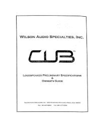
S e c t i o n 6 . 1 – T r o u b l e s h o o t i n gEnclosure Type Tweeter Module:Enclosure Type Midrange Module:Enclosure Type Woofer Module:Sealed, X-MaterialRear Vented, X- & S-MaterialRear Ported, X-MaterialWoofers:Midrange:Tweeter:One—8 inch (20.32 cm) Paper PulpOne—10 inches (25.4 cm) Paper Pulp7 inch (17.78 cm) Paper Pulp Composite1 inch (2.54 cm) Doped Silk FabricSensitivity:Nominal Impedance:Minimum Amplifier Power:Frequency Response:90 dB (one watt at one meter at 1Khz)4 ohms/minimum 2 ohms @ 80 Hz20 watts per channel20 Hz—32 kHz +/- 3 dB(with port contribution)Overall Dimensions:Height—53 1/4 inches (135.29 cm)Width—15 1/4 inches (38.74 cm)Depth—21 1/8 inches, (53.7 cm)<strong>Alexia</strong> Weight Per Channel:256 lbs (116.12 kg)<strong>Wilson</strong> <strong>Audio</strong> Specialties63
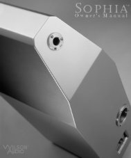
A l e x i a O w n e r ’ s M a n u a lSection 7.2—<strong>Alexia</strong> DimensionsFigure 1764<strong>Wilson</strong> <strong>Audio</strong> Specialties
Section 8—Propagation Delay Tables
<strong>Wilson</strong> <strong>Audio</strong> Specialties
S e c t i o n 8 . 1 — P r o p a g a t i o n D e l a y T a b l e sSection 8.1—Propagation Delay Tables<strong>Alexia</strong> Upper Array Spike LengthListening Distance8' 9' 10' 11' 12' 14' 16' 18' 20' 22' 24' 26'48 No Spike No Spike No Spike 2 2 2 2 3 3 3 3 446 No Spike 2 2 2 2 2 2 3 3 3 4 444 2 2 2 2 2 2 2 3 3 3 4 442 2 2 2 2 2 3 3 3 3 4 4 440 3 2 2 2 2 3 3 4 4 4 4 438 3 2 3 3 3 3 4 4 4 4 4 436 3 3 3 3 4 4 4 4 4 4 4 4<strong>Alexia</strong> Upper Array Alignment Block PositionListening Distance (feet)8' 9' 10' 11' 12' 14' 16' 18' 20' 22' 24' 26'48 2 5 7.5 3 4.5 7 9 7 8 8.5 9.5 546 5.5 2 3.5 5 6.5 9 10.5 8.5 10 10 11 6.544 3 4 7 8 9.5 11 12 10 10.5 11.5 6.5 6.542 6 7.5 9 10 11.5 9.5 10.5 12 12 7 8 8.540 5 11 12 13 13 11 12 7.5 8.5 8.5 8.5 1038 8.5 14 11 12 12 13 8 9 9 10 10 1036 12 13 14 14 9 10 10 11 10.5 10.5 12 12Ear Height (inches)Ear Height (inches)<strong>Wilson</strong> <strong>Audio</strong> Specialties67
A l e x i a O w n e r ’ s M a n u a l<strong>Alexia</strong> Upper Array Alignment Block StepListening Distance8' 9' 10' 11' 12' 14' 16' 18' 20' 22' 24' 26'48 6 8 10 3 4 6 7 6 7 7 8 546 8 2 3 4 5 7 8 7 8 8 9 644 2 3 5 6 7 8 9 8 8 9 6 642 4 5 6 7 8 7 8 9 9 6 7 740 3 7 8 9 9 9 9 5 7 7 7 838 5 9 7 8 8 9 6 7 7 8 8 836 7 8 9 9 7 7 7 8 8 8 9 9<strong>Alexia</strong> Tweeter Detent PositionListening Distance8' 9' 10' 11' 12' 14' 16' 18' 20' 22' 24' 26'48 2 3 4 4 5 6 7 7 8 8 8 946 2 3 4 4 5 6 7 7 8 8 8 944 2 3 4 4 5 6 7 7 8 8 8 942 2 3 4 4 5 6 7 7 8 8 8 940 2 3 4 4 5 6 7 7 8 8 8 938 2 3 4 4 5 6 7 7 8 8 8 936 2 3 4 4 5 6 7 7 8 8 8 9Ear Height (inches)Ear Height (inches)68<strong>Wilson</strong> <strong>Audio</strong> Specialties
Section 9—Warranty Information
<strong>Wilson</strong> <strong>Audio</strong> Specialties
S e c t i o n 9 . 1 — W a r r a n t y I n f o r m a t i o nSection 9.1—Warranty InformationLimited WarrantySubject to the conditions set forth herein, <strong>Wilson</strong> <strong>Audio</strong> warrants its loudspeakersto be free of manufacturing defects in material and workmanship for the WarrantyPeriod. The Warranty Period is a period of 90 days from the date of purchase by theoriginal purchaser, or if both of the following two requirements are met, the WarrantyPeriod is a period of five (5) years from the date of purchase by the original purchaser:Requirement No. 1. No later than 30 days after product delivery to thecustomer, the customer must have returned the Warranty RegistrationForm to <strong>Wilson</strong> <strong>Audio</strong>;Requirement No. 2. The product must have been professionally installed bythe <strong>Wilson</strong> <strong>Audio</strong> dealer that sold the product to the customer.FAILURE TO COMPLY WITH EITHER REQUIREMENT NO. 1 OR REQUIREMENT NO. 2WILL RESULT IN THE WARRANTY PERIOD BEING LIMITED TO A PERIOD OF 90 DAYSONLY.ConditionsThis Limited Warranty is also subject to the following conditions and limitations.The Limited Warranty is void and inapplicable if the product has been used or handledother than in accordance with the instructions in the owner’s manual, or has beenabused or misused, damaged by accident or neglect or in being transported, or if theproduct has been tampered with or service or repair of the product has been attemptedor performed by anyone other than <strong>Wilson</strong> <strong>Audio</strong>, an authorized <strong>Wilson</strong> <strong>Audio</strong> DealerTechnician or a service or repair center authorized by <strong>Wilson</strong> <strong>Audio</strong> to service or repairthe product. Contact <strong>Wilson</strong> <strong>Audio</strong> at (801) 377-2233 for information on location<strong>Wilson</strong> <strong>Audio</strong> Specialties71
A l e x i a O w n e r ’ s M a n u a lof <strong>Wilson</strong> <strong>Audio</strong> Dealers and authorized service and repair centers. Most repairs canbe made in the field. In instances where return to <strong>Wilson</strong> <strong>Audio</strong>’s factory is required,the dealer or customer must first obtain a return authorization. Purchaser must pay forshipping to <strong>Wilson</strong> <strong>Audio</strong>, and <strong>Wilson</strong> <strong>Audio</strong> will pay for shipping of its choice to returnthe product to purchaser. A RETURNED PRODUCT MUST BE ACCOMPANIED BYA WRITTEN DESCRIPTION OF THE DEFECT. <strong>Wilson</strong> <strong>Audio</strong> reserves the right to modifythe design of any product without obligation to purchasers of previously manufacturedproducts and to change the prices or specifications of any product without notice orobligation to any person.RemedyIn the event that the product fails to meet the above Limited Warranty and theconditions set forth herein have been met, the purchaser’s sole remedy under this LimitedWarranty shall be to: (1) contact an authorized <strong>Wilson</strong> <strong>Audio</strong> Dealer within theWarranty Period for service or repair of the product without charge for parts or labor,which service or repair, at the Dealer’s option, shall take place either at the locationwhere the product is installed or at the Dealer’s place of business; or (2) if purchaserhas timely sought service or repair and the product cannot be serviced or repaired bythe Dealer, then purchaser may obtain a return authorization from <strong>Wilson</strong> <strong>Audio</strong> and atpurchaser’s expense return the product to <strong>Wilson</strong> <strong>Audio</strong> where the defect will be rectifiedwithout charge for parts or labor.Warranty Limited to Original PurchaserThis Limited Warranty is for the sole benefit of the original purchaser of the coveredproduct and shall not be transferred to a subsequent purchaser of the product, unlessthe product is purchased by the subsequent purchaser from an authorized <strong>Wilson</strong><strong>Audio</strong> Dealer who has certified the product in accordance with <strong>Wilson</strong> <strong>Audio</strong> standards72<strong>Wilson</strong> <strong>Audio</strong> Specialties
S e c t i o n 9 . 1 — W a r r a n t y I n f o r m a t i o nand requirements and the certification has been accepted by <strong>Wilson</strong> <strong>Audio</strong>, in whichevent the Limited Warranty for the product so purchased and certified shall expire atthe end of the original Warranty Period applicable to the product.Demonstration EquipmentEquipment, while used by an authorized dealer for demonstration purposes, iswarranted to be free of manufacturing defects in materials and workmanship for a periodof five (5) years from the date of shipment to the dealer. Demo equipment needingwarranty service may be repaired on-site or, if necessary, correctly packed and returnedto <strong>Wilson</strong> <strong>Audio</strong> by the dealer at dealer’s sole expense. <strong>Wilson</strong> <strong>Audio</strong> will pay returnfreight of its choice. A returned product must be accompanied by a written descriptionof the defect. Dealer owned demonstration equipment sold at retail within two (2) yearsof date of shipment to the dealer is warranted to the first retail customer to be free ofmanufacturing defects in materials and workmanship for the same time periods as if theproduct had originally been bought for immediate resale to the retail customer. <strong>Wilson</strong><strong>Audio</strong> products are warranted for a period of 90 days, unless extended to 5 years, asprovided above, by return and filing of completed Warranty Registration at <strong>Wilson</strong> <strong>Audio</strong>within 30 days after product delivery to customer and the product was professionallyinstalled by the <strong>Wilson</strong> <strong>Audio</strong> Dealer that sold the product to the customer.MiscellaneousALL EXPRESS AND IMPLIED WARRANTIES NOT PROVIDED FOR HEREIN AREHEREBY EXPRESSLY DISCLAIMED. ANY LEGALLY IMPOSED IMPLIED WARRANTIES RE-LATING TO THE PRODUCT SHALL BE LIMITED TO THE DURATION OF THIS LIMITEDWARRANTY. THIS LIMITED WARRANTY DOES NOT EXTEND TO ANY INCIDENTAL ORCONSEQUENTIAL COSTS OR DAMAGES TO THE PURCHASER.Some states do not allow limitations on how long an implied warranty lasts or<strong>Wilson</strong> <strong>Audio</strong> Specialties73
A l e x i a O w n e r ’ s M a n u a lan exclusion or limitation of incidental or consequential damages, so the above limitationsor exclusions may not apply to you. This Limited Warranty gives you specificlegal rights, and you may also have other rights, which vary from state to state.74<strong>Wilson</strong> <strong>Audio</strong> Specialties