

Gilflo ILVA Flowmeters System Overview - Spirax Sarco
Gilflo ILVA Flowmeters System Overview - Spirax Sarco
Gilflo ILVA Flowmeters System Overview - Spirax Sarco

Create successful ePaper yourself
Turn your PDF publications into a flip-book with our unique Google optimized e-Paper software.
Cert. No. LRQ 0963008<br />
ISO 9001<br />
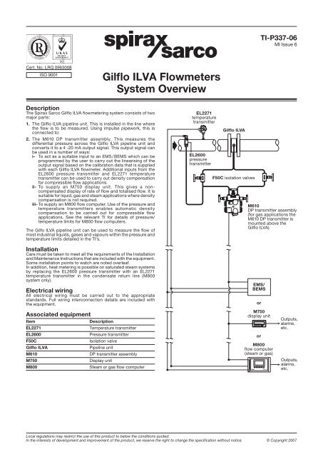
Description<br />
The <strong>Spirax</strong> <strong>Sarco</strong> <strong>Gilflo</strong> <strong>ILVA</strong> flowmetering system consists of two<br />
major parts:<br />
1. The <strong>Gilflo</strong> <strong>ILVA</strong> pipeline unit. This is installed in the line where<br />
the flow is to be measured. Using impulse pipework, this is<br />
connected to:<br />
2. The M610 DP transmitter assembly. This measures the<br />
differential pressure across the <strong>Gilflo</strong> <strong>ILVA</strong> pipeline unit and<br />
converts it to a 4 -20 mA output signal. This output signal can<br />
be used in a number of ways:<br />
i- To act as a suitable input to an EMS / BEMS which can be<br />
programmed by the user to carry out the linearising of the<br />
output signal based on the calibration data that is supplied<br />
with each <strong>Gilflo</strong> <strong>ILVA</strong> flowmeter. Additional inputs from the<br />
EL2600 pressure transmitter and EL2271 temperature<br />
transmitter can be used to carry out density compensation<br />
for compressible flow applications.<br />
ii- To supply an M750 display unit. This gives a noncompensated<br />
display of rate of flow and totalised flow. It is<br />
suitable for liquid, gas and steam applications where density<br />
compensation is not required.<br />
iii- To supply an M800 flow computer. Use of the pressure and<br />
temperature transmitters enables automatic density<br />
compensation to be carried out for compressible flow<br />
applications. See the relevant TI for details of pressure/<br />
temperature limits for M800 flow computers.<br />
The Gilfo <strong>ILVA</strong> pipeline unit can be used to measure the flow of<br />
most industrial liquids, gases and vapours within the pressure and<br />
temperature limits detailed in the TI's.<br />
Installation<br />
Care must be taken to meet all the requirements of the Installation<br />
and Maintenance Instructions that are included with the equipment.<br />
Some installation points to watch are noted overleaf.<br />
In addition, heat metering is possible on saturated steam systems<br />
by replacing the EL2600 pressure transmitter with an EL2271<br />
temperature transmitter in the condensate return line (M800<br />
system only).<br />
Electrical wiring<br />
All electrical wiring must be carried out to the appropriate<br />
standards. Full wiring interconnection details are included with<br />
the equipment.<br />
Associated equipment<br />
Item Description<br />
EL2271 Temperature transmitter<br />
EL2600 Pressure transmitter<br />
F50C Isolation valve<br />
<strong>Gilflo</strong> <strong>ILVA</strong> Pipeline unit<br />
M610 DP transmitter assembly<br />
M750 Display unit<br />
M800 Steam or gas flow computer<br />
<strong>Gilflo</strong> <strong>ILVA</strong> <strong>Flowmeters</strong><br />
<strong>System</strong> <strong>Overview</strong><br />
EL2271<br />
temperature<br />
transmitter<br />
EL2600<br />
pressure<br />
transmitter<br />
<strong>Gilflo</strong> <strong>ILVA</strong><br />
F50C isolation valves<br />
Local regulations may restrict the use of this product to below the conditions quoted.<br />
In the interests of development and improvement of the product, we reserve the right to change the specification without notice. © Copyright 2007<br />
����<br />
TI-P337-06<br />
MI Issue 6<br />
M610<br />
DP transmitter assembly<br />
(for gas applications the<br />
M610 DP transmitter is<br />
mounted above the<br />
<strong>Gilflo</strong> <strong>ILVA</strong>)<br />
EMS/<br />
BEMS<br />
or<br />
M750<br />
display unit<br />
or<br />
M800<br />
flow computer<br />
(steam or gas)<br />
��<br />
Outputs,<br />
alarms,<br />
etc.<br />
Outputs,<br />
alarms,<br />
etc.
Installation points to watch:<br />
1. Ensure that all pipework is adequately supported and properly aligned. Special care should be taken to ensure that the <strong>Gilflo</strong> <strong>ILVA</strong><br />
pipeline unit is concentrically mounted in the line.<br />
2. The <strong>Gilflo</strong> <strong>ILVA</strong> pipeline unit should be selected on capacity rather than line size. Where line size changes on steam systems are<br />
necessary, use eccentric reducers to avoid build-up of condensate.<br />
3. The minimum recommended lengths of straight pipe upstream and downstream are 6 D and 3 D respectively. See other literature<br />
for more details concerning the <strong>Gilflo</strong> <strong>ILVA</strong>.<br />
4. Take care to ensure the correct direction of flow as indicated by the arrow on the flowmeter body.<br />
5. Take care to avoid reverse flow through the flowmeter.<br />
6. Avoid installing the flowmeter downstream of a pressure reducing valve (especially on steam systems) as this may cause inaccurate<br />
readings. Similarly, avoid installing the flowmeter downstream of a partially open valve.<br />
7. Remember that actuated valves may cause rapid pressure fluctuations which could cause damage.<br />
8. On steam or liquid systems, the M610 DP transmitter assembly is mounted below the flowmeter. Take care to ensure that all impulse<br />
lines remain full to prevent damage to the DP transmitter through contact with steam or high temperature liquid.<br />
9. For steam applications, care should be taken to ensure adequate line drainage, trapping etc., to avoid condensate slugs impacting the<br />
flowmeter. Where practicable, steam separators should be fitted. These should be drained using a float trap set.<br />
10. For gas applications, the M610 DP transmitter assembly is installed above the pipework. Ensure that the impulse lines allow<br />
free drainage of moisture away from the DP transmitter and back into the pipeline.<br />
<strong>Gilflo</strong> <strong>ILVA</strong> <strong>Flowmeters</strong> <strong>System</strong> <strong>Overview</strong><br />
TI-P337-06 MI Issue 6


