Gilflo ILVA Flowmeter DN250 and DN300 - Spirax Sarco
Gilflo ILVA Flowmeter DN250 and DN300 - Spirax Sarco
Gilflo ILVA Flowmeter DN250 and DN300 - Spirax Sarco

Create successful ePaper yourself
Turn your PDF publications into a flip-book with our unique Google optimized e-Paper software.
Cert. No. LRQ 0963008<br />
ISO 9001<br />
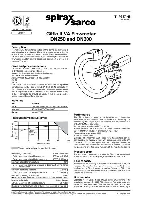
Description<br />
The <strong>Gilflo</strong> <strong>ILVA</strong> flowmeter operates on the spring loaded variable<br />
area principle <strong>and</strong> produces a differential pressure related to the rate<br />
of flow. It can be used with most industrial fluids, gases <strong>and</strong> both<br />
saturated <strong>and</strong> superheated steam. A general description of the <strong>ILVA</strong><br />
flowmetering system <strong>and</strong> its associated equipment is given in a<br />
separate TI sheet.<br />
Sizes <strong>and</strong> pipe connections<br />
<strong>DN250</strong> <strong>and</strong> <strong>DN300</strong>. For DN50, DN80, DN100, DN150 <strong>and</strong><br />
DN200 sizes see separate literature.<br />
Suitable for fitting between the following flanges:<br />
EN 1092 PN16, PN25 <strong>and</strong> PN40.<br />
ASME (ANSI) B 16.5 Class 150, 300 <strong>and</strong> 600.<br />
JIS 20.<br />
KS 20.<br />
The <strong>Gilflo</strong> <strong>ILVA</strong> flowmeter should be installed in pipework<br />
manufactured to BS 1600 or ASME (ANSI) B 36.10 Schedule 40.<br />
For different pipe st<strong>and</strong>ards / schedules, downstream spool pieces<br />
with an equivalent internal diameter to BS 1600 or ASME (ANSI)<br />
B 36.10 Schedule 40 should be used. If this is not possible,<br />
please contact <strong>Spirax</strong> <strong>Sarco</strong> Limited.<br />
Materials<br />
Part Material<br />
Body Cast stainless steel S.316 (CF8M/1.4408)<br />
Internals 431 S29/S303/S304/S316<br />
Spring Inconel X750<br />
Pressure / temperature limits<br />
Temperature °C<br />
400<br />
300<br />
200<br />
100<br />
0<br />
-29<br />
0<br />
Steam<br />
saturation<br />
curve<br />
<strong>Gilflo</strong> <strong>ILVA</strong> <strong>Flowmeter</strong><br />
<strong>DN250</strong> <strong>and</strong> <strong>DN300</strong><br />
20 40 60 80 100<br />
Pressure bar g<br />
The product must not be used in this region.<br />
Body design conditions ASME (ANSI) 600<br />
PMA Maximum allowable pressure 100 bar g @ 50°C<br />
TMA Maximum allowable temperature 400°C @ 69 bar g<br />
Minimum allowable temperature -29°C<br />
PMO<br />
Maximum operating pressure is dependant on the flange<br />
specification<br />
Minimum operating pressure 0.6 bar g<br />
TMO Maximum operating temperature 400°C @ 69 bar g<br />
Minimum operating temperature -29°C<br />
Note: For lower operating temperatures consult <strong>Spirax</strong> <strong>Sarco</strong><br />
Maximum viscosity 30 centipoise<br />
DPMX Maximum differential pressure 498 m bar<br />
Designed for a maximum cold hydraulic test pressure of 155 bar g<br />
TI-P337-46<br />
MI Issue 2<br />
Performance<br />
The <strong>Gilflo</strong> <strong>ILVA</strong> is used in conjunction with linearising<br />
electronics such as the M800 flow computer or M750 display unit.<br />
Alternatively the output signal linearisation can be performed on<br />
an EMS / BEMS or equivalent.<br />
Accuracy when used with M800 or M750:<br />
±1% of measured value from 5% to 100% of maximum rated flow.<br />
±0.1% FSD from 1% to 5% of maximum rated flow.<br />
Repeatability better than 0.25%<br />
Turndown: up to 100:1<br />
Caution: The Scanner 2000 mass flow transmitters can be<br />
configured at the factory to work with a single, specific <strong>Gilflo</strong> <strong>ILVA</strong><br />
flowmeter. For correct operation the configured transmitter<br />
must always be installed with its allocated flowmeter. Labels on<br />
the packaging give the serial numbers of the matched products.<br />
Pressure drop<br />
The maximum pressure drop across the <strong>Gilflo</strong> <strong>ILVA</strong> pipeline unit<br />
is 498 m bar (200 ins water gauge) at maximum rated flow.<br />
Flow capacity<br />
To determine the capacity of the <strong>Gilflo</strong> <strong>ILVA</strong> for different fluids, it is<br />
necessary to calculate the equivalent water flowrate QE (in l/min)<br />
as described in Step 1, under the section 'sizing the <strong>Gilflo</strong> <strong>ILVA</strong>'<br />
then selecting the appropriate size of flowmeter from the Table<br />
under Step 2 overleaf.<br />
How to order<br />
Example: 1 off <strong>Spirax</strong> <strong>Sarco</strong> <strong>DN250</strong> <strong>Gilflo</strong> <strong>ILVA</strong> flowmeter for<br />
installation between EN 1092 PN40 flanges. The body material is<br />
to be 316 stainless steel. The flow medium will be saturated<br />
steam at 10 bar g <strong>and</strong> the maximum flow will be 28 000 kg/h.<br />
Local regulations may restrict the use of this product to below the conditions quoted.<br />
In the interests of development <strong>and</strong> improvement of the product, we reserve the right to change the specification without notice. © Copyright 2010
Dimensions/weights (approximate) in mm <strong>and</strong> kg<br />
Size A B C D E F Weight<br />
<strong>DN250</strong> 104 204 444 330 35.0 35 41.5<br />
<strong>DN300</strong> 120 250 530 385 42.5 35 67.0<br />
Note:- Pressure tappings are threaded ¼" NPT<br />
Safety information, installation <strong>and</strong> maintenance<br />
For full details see the Installation <strong>and</strong> Maintenance Instructions<br />
supplied with the product.<br />
Installation note:<br />
The following main points are given here for guidance:<br />
1. The <strong>Gilflo</strong> <strong>ILVA</strong> should be mounted with a minimum of 6 straight<br />
pipe diameters upstream <strong>and</strong> 3 downstream. No valves, fittings<br />
or cross sectional changes are permitted within these pipe<br />
lengths. Where an increase in nominal pipe diameter is required<br />
upstream of the flowmeter, the length of straight pipe should be<br />
increased to 12 diameters. Similarly, where a <strong>Gilflo</strong> <strong>ILVA</strong> is<br />
installed downstream of two 90 degree bends in two planes,<br />
a pressure reducing valve or a partially open valve, 12 upstream<br />
pipe diameters should be allowed.<br />
2. It is important that the internal upstream <strong>and</strong> downstream diameters<br />
of pipe are smooth. Ideally seamless pipes should be used. It is<br />
recommended that slip-on flanges be used to avoid any intrusive<br />
weld beads on the internal diameter of the pipe.<br />
3. Care should be taken to install the <strong>Gilflo</strong> <strong>ILVA</strong> concentrically in the<br />
line. If this is not done, flow measurement errors may occur.<br />
4. The <strong>Gilflo</strong> <strong>ILVA</strong> should be mounted horizontally. For vertical<br />
installations, consult <strong>Spirax</strong> <strong>Sarco</strong>.<br />
5. For steam applications, good basic steam engineering practices<br />
should be followed:<br />
- Correct line drainage through adequate trapping.<br />
- Good alignment <strong>and</strong> support of associated pipework.<br />
- Line size changes achieved by the use of eccentric reducers.<br />
Sizing the <strong>Gilflo</strong> <strong>ILVA</strong> flowmeter<br />
In order to determine the flow capacity of a <strong>Gilflo</strong> <strong>ILVA</strong> pipeline unit,<br />
it is necessary to calculate the equivalent water flowrate (Q E )<br />
based on the anticipated actual flow (see Step 1).<br />
The Table below is used to select the appropriate unit (steam only).<br />
Step 1. Determine equivalent water flowrate (Q E ) in l/min:-<br />
Liquids<br />
Gases<br />
<strong>and</strong> steam<br />
actual flow<br />
conditions<br />
Gases<br />
st<strong>and</strong>ard<br />
conditions<br />
Maintenance note:<br />
Q = 6 174 litres / min<br />
E<br />
There are no user serviceable parts in the <strong>Gilflo</strong> <strong>ILVA</strong>. A visual<br />
check together with confirmation that the orifice / cone reference So a <strong>DN250</strong> <strong>ILVA</strong> is recommended.<br />
dimension is within tolerance is possible.<br />
Note: 1 m³ / h = 16.667 litres / min<br />
Sizing - <strong>Gilflo</strong> <strong>ILVA</strong> flowmeter minimum <strong>and</strong> maximum saturated steam flowrates in kg / h<br />
Notes:<br />
1. These capacities are based on a differential pressure across the flowmeter of 498 m bar H20 (200 Inches).<br />
2. Minimum flow is 1% of maximum (100:1 turndown).<br />
3. The table below is a guide only.<br />
Size<br />
<strong>DN250</strong><br />
<strong>DN300</strong><br />
E<br />
D<br />
F<br />
A<br />
B<br />
Note: Pressure tappings<br />
(2 off located on one side only)<br />
C<br />
Mass flow units Volumetric units<br />
Q E =<br />
qm<br />
SG<br />
Q E = QL SG<br />
Where:<br />
Q = Equivalent water flowrate (litres/min)<br />
E<br />
q = Mass flowrate (kg /min)<br />
m<br />
Q = Maximum liquid flowrate (litres/min)<br />
L<br />
Q = Maximum gas flowrate at st<strong>and</strong>ard conditions (litres/min)<br />
S<br />
Q = Maximum gas flowrate at actual flow conditions (litres/min)<br />
F<br />
SG = Specific gravity<br />
D = Density of gas at st<strong>and</strong>ard conditions (kg /m³)<br />
S<br />
D = Density of gas at actual flow conditions (kg /m³)<br />
F<br />
P = St<strong>and</strong>ard pressure: 1 S . 013 bar a, 1 . 033 kg/cm 2 a, 14.70 psi a<br />
P = Actual flow pressure in same absolute units as P F S<br />
TS TF Q = q<br />
E M<br />
= St<strong>and</strong>ard temperature (K) = °C + 273<br />
= Actual flow temperature (K) = °C + 273<br />
Step 2. Using the value of Q E as determined in Step 1, select the<br />
correct size of the <strong>Gilflo</strong> <strong>ILVA</strong> flowmeter using the Table below. In<br />
practice, it will often be the line size that determines the choice of<br />
the flowmeter.<br />
<strong>Flowmeter</strong> type Max. QE litres / min<br />
Maximum pressure drop<br />
Wg<br />
<strong>DN250</strong> 7 750 200<br />
<strong>DN300</strong> 10 975 200<br />
Example: Determine which <strong>Gilflo</strong> pipeline unit is required to<br />
measure the flow of compressed air when:<br />
1: Estimated maximum rate of flow = 28000 s m³ /h at 7 bar g <strong>and</strong> 20°C.<br />
Note: St<strong>and</strong>ard conditions = 1.013 bar a, 0°C giving a st<strong>and</strong>ard<br />
density of 1.29 kg / m³<br />
2: Calculate Q E from:<br />
1000<br />
D<br />
D P P<br />
Q E = Q S x x<br />
1000 P T<br />
<strong>Gilflo</strong> <strong>ILVA</strong> <strong>Flowmeter</strong> <strong>DN250</strong> <strong>and</strong> <strong>DN300</strong> TI-P337-46 MI Issue 2<br />
F<br />
S F F<br />
S S<br />
DF<br />
Q E = QF 1000<br />
D P T S S F<br />
Q = Q DS PF P<br />
E S<br />
F<br />
Q E = x Q x<br />
1 000 PF S T x x<br />
1000 S PS TS<br />
Ö<br />
D P T S S F<br />
Q = Q x x<br />
E S 1 000 PF TS 1.29 1.013 293<br />
1000 8.013 273<br />
Q E =(28000 x 16.667) x x x<br />
QE 1 3 5 7<br />
Steam pressure bar g<br />
10 12 15 20 25 30 40<br />
Max. 7 750 15 985 22 185 26 915 30 899 36 043 39 099 43 292 49 541 55 155 60 325 69 758<br />
Min. 78 160 222 269 309 433 391 433 495 552 603 698<br />
Max. 10 975 22 637 31 417 38 115 43 758 51 042 55 369 61 307 70 157 78 107 85 428 98 778<br />
Min. 110 226 314 381 438 510 554 613 702 781 854 988<br />
How to order example: 1 off <strong>Spirax</strong> <strong>Sarco</strong> <strong>DN250</strong> <strong>ILVA</strong> flowmeter suitable for fitting between EN 1092 PN16 connections.<br />
Ö