Orifice Plate Flowmeters for Steam, Liquids and Gases - Spirax Sarco
Orifice Plate Flowmeters for Steam, Liquids and Gases - Spirax Sarco
Orifice Plate Flowmeters for Steam, Liquids and Gases - Spirax Sarco

You also want an ePaper? Increase the reach of your titles
YUMPU automatically turns print PDFs into web optimized ePapers that Google loves.
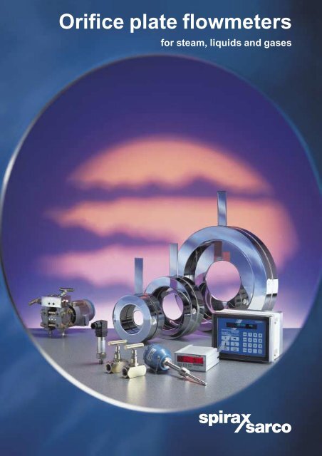
<strong>Orifice</strong> plate flowmeters<br />
<strong>for</strong> steam, liquids <strong>and</strong> gases
2<br />
Why measure flow?<br />
In many of today’s industrial processes, it is essential<br />
to measure accurately the rate of fluid flow within a<br />
system as a whole or in part. This applies equally to<br />
gases <strong>and</strong> liquids (e.g. carbon dioxide, nitrogen, liquors<br />
etc.) which are an integral part of the process, or to<br />
compressed air, water or steam which are fundamental<br />
to plant operation. The installation of any flowmeter<br />
can be justified in one of two ways:<br />
1. Process control<br />
Here the flowmeter is used to measure the rate of fluid<br />
or energy flow to allow the process to be controlled <strong>and</strong><br />
so ensure that the end product is of the required<br />
quality. A common example of this would be in steam<br />
injection systems <strong>for</strong> the animal feeds industry...too<br />
much steam <strong>and</strong> the product will not pellet...too little<br />
steam <strong>and</strong> the raw materials will not process <strong>and</strong> may<br />
damage the production machinery.<br />
2. Cost allocation<br />
Where energy is used to provide process or space<br />
heating, it is fundamental to know where the costs<br />
associated with the energy are actually being incurred.<br />
Flowmetering allows energy costs to be allocated to a<br />
particular product, department or other user this usually<br />
resulting in a significant reduction in total energy costs.<br />
Measuring flow allows you to:-<br />
Improve process control<br />
Allocate heating costs<br />
Identify major energy users<br />
Monitor the results of process changes<br />
Check on steam boiler efficiency<br />
Identify energy patterns through the day<br />
Provide management in<strong>for</strong>mation<br />
Lord Kelvin once said:<br />
“When you can measure what you are speaking about<br />
<strong>and</strong> express it in numbers, you know something about<br />
it; but when you cannot measure it, when you cannot<br />
express it in numbers, your knowledge is of a meagre<br />
<strong>and</strong> unsatisfactory kind.”<br />
In other words, you cannot manage what you cannot<br />
measure <strong>and</strong> nowhere is that more true than in the<br />
measurement of flow.<br />
Tab h<strong>and</strong>led<br />
orifice plate<br />
Upstream<br />
pressure tapping<br />
Gasket<br />
Rate of flow kg/h<br />
1 000<br />
800<br />
600<br />
400<br />
200<br />
Flow<br />
Flowrate<br />
Actual system<br />
pressure<br />
Cumulative error<br />
0<br />
0 1 2 3 4 5 6<br />
Hours elapsed
10<br />
8<br />
6<br />
4<br />
2<br />
0<br />
7 8<br />
Pressure bar g<br />
2 500<br />
2 000<br />
1 500<br />
1 000<br />
500<br />
0<br />
Cumulative error kg<br />
Downstream<br />
pressure tapping<br />
Carrier plate <strong>for</strong><br />
clamping between<br />
flanges<br />
Optional<br />
drain hole<br />
Why use orifice plates?<br />
<strong>Orifice</strong> plates are still the most widely used type of<br />
flowmeter in the world today. They offer significant cost<br />
benefits over other types of flowmeter, especially in<br />
larger line sizes, <strong>and</strong> have proved to be rugged, effective<br />
<strong>and</strong> reliable over many years. Where a need exists <strong>for</strong> a<br />
rugged, cost effective flowmeter which has a low<br />
installation cost <strong>and</strong> a turndown of not more than 4:1,<br />
the orifice plate continues to offer a very competitive<br />
solution.<br />
DP<br />
How do orifice plates work ?<br />
An orifice plate installed in a line creates a pressure<br />
differential as the fluid flows through it. This differential<br />
pressure is measured via impulse lines by a differential<br />
pressure transmitter which converts it into an analogue<br />
or digital signal which can be processed to provide a<br />
display of the instantaneous rate of flow. The<br />
relationship between the rate of flow <strong>and</strong> the differential<br />
pressure produced is very well understood <strong>and</strong> is fully<br />
covered by comprehensive national st<strong>and</strong>ards. The<br />
relevant st<strong>and</strong>ards are BS 1042 <strong>and</strong> the equivalent<br />
ISO 5167. One of the principle advantages of orifice<br />
plates manufactured <strong>and</strong> installed following these<br />
st<strong>and</strong>ards is that they do not require calibration. This<br />
means that orifice plates are very cost effective on<br />
larger line sizes.<br />
Density compensation<br />
With liquid metering systems, the flowing density is usually fairly constant <strong>and</strong> relatively<br />
simple processing of the output signal from the differential pressure transmitter is usually<br />
all that is required.<br />
However, it is rare <strong>for</strong> the pressure in steam systems to remain absolutely constant.<br />
Unless this is taken into account, flow measurement errors will occur. By using the<br />
automatic density compensation capability of the <strong>Spirax</strong> <strong>Sarco</strong> M240G <strong>Steam</strong> Flow<br />
Computer, these errors are completely eliminated allowing accurate steam metering<br />
whatever the steam pressure.<br />
Example: A simple non compensated flowmeter is set <strong>for</strong> 6 bar g. The actual pressure in<br />
the system varies through the day <strong>and</strong> unless this is allowed <strong>for</strong>, by the end of the day,<br />
very significant errors can arise. This is typical of many steam systems.<br />
3
4<br />
<strong>Spirax</strong> <strong>Sarco</strong> orifice plate flowmeters - the system<br />
<strong>Orifice</strong> plates are amongst the most simple <strong>and</strong> easy to use type of flowmeter. However, in order to get the very<br />
best out of them, it is essential to ensure that the user specifies a complete system that meets his requirements.<br />
All too often, factors such as the need <strong>for</strong> density compensation are not fully specified by the user with the result<br />
that the full potential of the orifice plate primary element is not achieved. Frequently, it is necessary to source<br />
items from several different manufacturers <strong>and</strong> hope that the components will be compatible.<br />
<strong>Spirax</strong> <strong>Sarco</strong> has completely eliminated this by introducing a range of orifice plate based flowmetering systems<br />
suitable <strong>for</strong> use on steam, liquids <strong>and</strong> gases. One of these systems will be ideal <strong>for</strong> your application. Select the<br />
system that is best suited <strong>for</strong> your needs from the 14 options available then decide on the display you<br />
need.....M700 <strong>for</strong> simple non compensated applications or the M240G steam flow computer <strong>for</strong> the ultimate in<br />
steam flow measurement capability. <strong>Spirax</strong> <strong>Sarco</strong> can advise, if necessary, which is the best system <strong>for</strong> any<br />
application.<br />
F50C Isolation<br />
valve<br />
Flow<br />
M610<br />
DP transmitter<br />
assembly<br />
User benefits<br />
All items available from a single equipment<br />
supplier.<br />
EL2271<br />
Temperature<br />
transmitter<br />
A complete range of systems available <strong>for</strong> most<br />
applications.<br />
Systems available <strong>for</strong> steam, liquids <strong>and</strong> gases.<br />
All orifice sizing calculations carried out<br />
by <strong>Spirax</strong> <strong>Sarco</strong> to BS 1042 / ISO 5167.<br />
Spare plates available.<br />
Available to suit most flange specifications.<br />
Wide range of sizes from DN25 up to DN600.<br />
M240G<br />
<strong>Steam</strong> flow<br />
computer<br />
Note: Configuration shown<br />
here is <strong>for</strong> steam. Gas <strong>and</strong><br />
liquid installations will differ.<br />
M410 <strong>Orifice</strong> plate<br />
assembly<br />
EL2600 Pressure<br />
transmitter<br />
Outputs<br />
Alarms etc.<br />
M700<br />
Display unit
approach that makes it simple<br />
Step 1<br />
Choose the orifice plate option<br />
M410 tab h<strong>and</strong>led orifice plate<br />
to BS 1042 / ISO 5167 complete<br />
with gaskets ... designed to be<br />
clamped between the user's<br />
own flanges, this is the<br />
simplest option.<br />
Or<br />
M410 orifice plate, gaskets,<br />
carrier ring with the addition of<br />
two F50C isolation valves to<br />
provide primary isolation.<br />
Step 2<br />
Choose the differential pressure transmitter<br />
High accuracy M610<br />
differential pressure transmitter<br />
fitted with a three-way manifold<br />
<strong>for</strong> isolation <strong>and</strong> zero<br />
adjustment.<br />
Where pressure <strong>and</strong> / or temperature varies then it is necessary to compensate <strong>for</strong> density variations <strong>and</strong><br />
the following options should be considered:-<br />
Step 3<br />
Choose the pressure transmitter <strong>for</strong> applications<br />
where the line pressure varies<br />
EL2600 pressure transmitter.<br />
Step 4<br />
Choose the temperature transmitter <strong>for</strong> applications<br />
where the line temperature varies<br />
EL2271 temperature<br />
transmitter <strong>for</strong> line<br />
temperatures up to 250°C<br />
Or<br />
EL2270 temperature sensor<br />
<strong>and</strong> separate EL2810<br />
temperature transmitter <strong>for</strong><br />
temperatures above 250 o C.<br />
OPTIONS<br />
1 2 3 4 5 6 7 8 9 10 11 12 13 14<br />
� � � � � � �<br />
� � � � � � �<br />
OPTIONS<br />
1 2 3 4 5 6 7 8 9 10 11 12 13 14<br />
� � � � � � � � � � � �<br />
OPTIONS<br />
5 6 7 8 9 10 11 12 13 14<br />
� � � � � �<br />
OPTIONS<br />
5 6 7 8 9 10 11 12 13 14<br />
� � � �<br />
� � � �<br />
Example: Option 7 would include 1 x M410, 1 x M610, 1 x EL2270 <strong>and</strong> 1 x EL2810.<br />
5
6<br />
Installation of orifice plate flowmeters<br />
Almost all flowmeters need certain lengths of straight,<br />
uninterrupted pipe upstream <strong>and</strong> downstream of the<br />
flowmeter itself, <strong>and</strong> orifice plates are no exception. As<br />
the per<strong>for</strong>mance of orifice plates is based on theoretical<br />
predictions, the installation is very important <strong>and</strong> is<br />
described in detail in national st<strong>and</strong>ards BS 1042 <strong>and</strong><br />
ISO 5167. The recommened minimum lengths are<br />
shown here.<br />
Minimum number of pipeline diameters required<br />
upstream of M410 orifice plate.<br />
b<br />
For guidance a b ratio of 0.7 should be used<br />
b
Dimensions (approximate in mm)<br />
The M410 is available as a tab h<strong>and</strong>led<br />
plate that can be located between<br />
customers flanges or fitted in its own<br />
carrier with integral pressure tappings.<br />
BS 4504 BS 4504 BS 4504 BS10<br />
Weight<br />
ANSI 150 ANSI 300 ANSI 600 JIS20 KS20<br />
PN16 PN25 PN40 Table H (see note 6)<br />
Size A A A A A A A A A kg<br />
DN25 73 73 73 71.4 66.7 73.0 73.0 74 74 2.36<br />
DN40 94 94 94 88.9 85.7 95.3 95.3 89 89 3.72<br />
DN50 109 109 109 111.1 104.7 111.1 111.1 104 104 4.91<br />
DN65 129 129 129 130.1 123.8 130.2 130.2 124 124 6.21<br />
DN80 144 144 144 149.2 136.5 149.3 149.3 140 140 7.91<br />
DN100 164 170 170 174.6 174.6 181.0 193.7 165 165 13.75<br />
DN125 194 196 196 215.9 196.9 216.0 241.3 203 203 20.98<br />
DN150 220 226 226 241.3 222.3 250.9 266.7 238 238 23.51<br />
DN200 275 286 293 304.9 279.4 308.0 320.6 383 383 31.25<br />
DN250 331 343 355 358.8 339.7 361.9 400.0 356 356 47.95<br />
DN300 386 403 420 415.9 409.6 422.2 457.1 406 400 58.74<br />
DN350 446 460 477 469.9 450.8 485.7 492.1 450 450 60.20<br />
DN400 498 517 549 527.0 574.3 539.7 565.1 570 570 85.99<br />
DN450 559 567 574 581.0 549.2 596.8 612.7 575 575 94.38<br />
DN500 620 627 631 644.5 606.4 654.0 682.6 630 630 117.69<br />
DN600 737 734 750 749.3 717.5 774.7 790.6 734 734 146.37<br />
note 4<br />
B<br />
Notes:<br />
1. Dimension C is 25.4 mm <strong>for</strong> all sizes in line with<br />
BS 1042 / ISO 5167.<br />
2. For line sizes DN25 to DN350, orifice plate thickness T is 3 mm,<br />
above DN350, T is 6 mm.<br />
3. Gaskets are 1.6 mm thick.<br />
4. For line sizes up to DN350, carrier assembly thickness B is 82 mm,<br />
above DN350, B is 85 mm.<br />
5. An optional drain hole that meets BS 1042 can be incorporated<br />
if required.<br />
6. Maximum weights shown above are based on ANSI 600 flanges.<br />
A<br />
T, note 2<br />
C, note 1<br />
note 5<br />
note 3<br />
M410 <strong>Orifice</strong> plate<br />
F50C Isolation valves<br />
The F50C is a needle type isolation valve designed <strong>for</strong><br />
primary isolation flowmetering applications <strong>for</strong> steam<br />
<strong>and</strong> other industrial fluids.<br />
Connection<br />
½" NPT<br />
B A<br />
A B C Weight (kg)<br />
66 28 76 0.5<br />
Materials<br />
Body Passivated zinc plated carbon steel<br />
Seals Graphoil<br />
Limiting conditions<br />
Maximum operating pressure 413 bar g<br />
Maximum operating temperature 430°C<br />
C<br />
7
Technical in<strong>for</strong>mation<br />
Description<br />
The M410 orifice plate <strong>and</strong> carrier assembly is a<br />
primary flow element consisting of a tab h<strong>and</strong>led<br />
square edged orifice plate <strong>and</strong> optional carrier. The<br />
orifice plate is designed <strong>and</strong> manufactured to meet<br />
the requirements of BS 1042 <strong>and</strong> ISO 5167 in all<br />
respects <strong>and</strong> is suitable <strong>for</strong> measuring the flowrate of<br />
most liquids, gases <strong>and</strong> steam. The tab h<strong>and</strong>led orifice<br />
plate can be used:<br />
1) On its own fitted between flanges with pressure<br />
tappings in the users pipework or flanges, or;<br />
or<br />
2) Fitted into a carrier with integral flange tappings<br />
designed to fit between customer flanges.<br />
Materials<br />
Tab h<strong>and</strong>led orifice plate BS 1449 S316<br />
Carrier Passivated zinc plated carbon steel<br />
Gaskets Exfoilated graphite<br />
Pipe sizes available<br />
DN25, 40, 50, 65, 80, 100, 125, 150, 200, 250,<br />
300, 350, 400, 450, 500, 600<br />
Limiting conditions<br />
The tab h<strong>and</strong>led orifice plate <strong>and</strong> carrier<br />
assembly are suitable <strong>for</strong> use up to the limiting<br />
conditions of the specified flanges.<br />
Accuracy<br />
To BS 1042 <strong>and</strong> ISO 5167.<br />
The per<strong>for</strong>mance of an orifice plate flowmetering<br />
system can be greatly influenced by installation<br />
variables, so the figures given below are <strong>for</strong><br />
guidance only:<br />
Accuracy: typically +/- 3 % of actual flow.<br />
(equivalent to +/- 1.5 % full scale deflection at<br />
50 % of rated maximum flow).<br />
Repeatability: typically +/- 0.3 %.<br />
Turndown: typically 4:1.<br />
Connections<br />
Tab h<strong>and</strong>led plates <strong>and</strong> carriers are available<br />
to suit the following flange specifications:<br />
BS 4504 PN16, PN25 <strong>and</strong> PN40.<br />
BS 10 Table H.<br />
ANSI B 16.5 class 150, 300 <strong>and</strong> 600.<br />
Japanese Industrial St<strong>and</strong>ard JIS 20.<br />
Pressure tappings<br />
When the tab h<strong>and</strong>led orifice plates are used without the<br />
optional carrier, it is the responsibility of the user to<br />
provide appropriate presssure tappings in either his<br />
flanges or in the upstream <strong>and</strong> downstream pipework as<br />
specified in BS 1042 / ISO 5167.<br />
The optional carrier assembly incorporates upstream<br />
<strong>and</strong> downstream pressure tappings threaded ½" NPT.<br />
These tappings are 25.4 mm either side of the orifice<br />
plate face in line with the requirements of BS 1042 /<br />
ISO 5167.<br />
For full technical details of associated equipment, see relevant <strong>Spirax</strong> <strong>Sarco</strong> literature.<br />
Some of the products shown may not be available in certain markets.<br />
<strong>Spirax</strong>-<strong>Sarco</strong> Limited, Charlton House,<br />
Cheltenham, Gloucestershire, GL53 8ER UK.<br />
Tel: +44 (0)1242 521361 Fax: +44 (0)1242 573342<br />
E-mail: Enquiries@<strong>Spirax</strong><strong>Sarco</strong>.com<br />
Internet: www.<strong>Spirax</strong><strong>Sarco</strong>.com<br />
© Copyright 2000 <strong>Spirax</strong> <strong>Sarco</strong> is a registered trademark of <strong>Spirax</strong>-<strong>Sarco</strong> Limited<br />
SB-S66-11<br />
MI Issue 4<br />
OPLATE