

Gilflo 'B' Flowmeter Pipeline Unit - Spirax Sarco
Gilflo 'B' Flowmeter Pipeline Unit - Spirax Sarco
Gilflo 'B' Flowmeter Pipeline Unit - Spirax Sarco

Create successful ePaper yourself
Turn your PDF publications into a flip-book with our unique Google optimized e-Paper software.
Cert. No. LRQ 0963008<br />
ISO 9001<br />
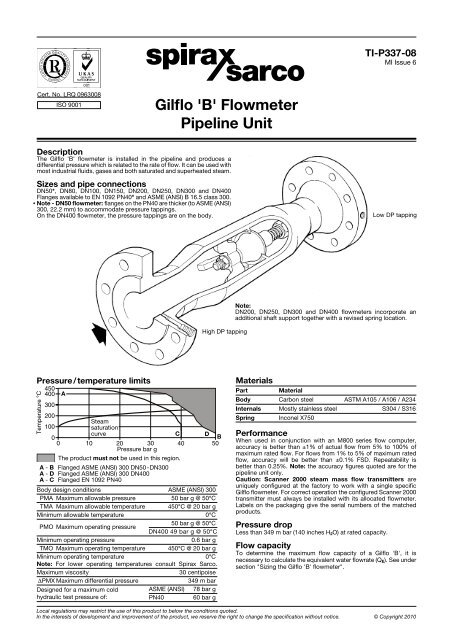
450<br />
400<br />
300<br />
200<br />
100<br />
Steam<br />
saturation<br />
0<br />
0<br />
curve<br />
10 20 30<br />
Pressure bar g<br />
C<br />
40<br />
D<br />
B<br />
50<br />
The product must not be used in this region.<br />
A - B Flanged ASME (ANSI) 300 DN50-DN300<br />
A - D Flanged ASME (ANSI) 300 DN400<br />
A - C Flanged EN 1092 PN40<br />
Body design conditions ASME (ANSI) 300<br />
PMA Maximum allowable pressure 50 bar g @ 50°C<br />
TMA Maximum allowable temperature 450°C @ 20 bar g<br />
Minimum allowable temperature 0°C<br />
PMO Maximum operating pressure<br />
50 bar g @ 50°C<br />
DN400 49 bar g @ 50°C<br />
Minimum operating pressure 0.6 bar g<br />
TMO Maximum operating temperature 450°C @ 20 bar g<br />
Minimum operating temperature 0°C<br />
Note: For lower operating temperatures consult <strong>Spirax</strong> <strong>Sarco</strong>.<br />
Maximum viscosity 30 centipoise<br />
DPMX Maximum differential pressure 349 m bar<br />
Designed for a maximum cold ASME (ANSI) 78 bar g<br />
hydraulic test pressure of: PN40 60 bar g<br />
<strong>Gilflo</strong> <strong>'B'</strong> <strong>Flowmeter</strong><br />
<strong>Pipeline</strong> <strong>Unit</strong><br />
Description<br />
The <strong>Gilflo</strong> <strong>'B'</strong> flowmeter is installed in the pipeline and produces a<br />
differential pressure which is related to the rate of flow. It can be used with<br />
most industrial fluids, gases and both saturated and superheated steam.<br />
Sizes and pipe connections<br />
DN50*, DN80, DN100, DN150, DN200, DN250, DN300 and DN400<br />
Flanges available to EN 1092 PN40* and ASME (ANSI) B 16.5 class 300.<br />
* Note - DN50 flowmeter: flanges on the PN40 are thicker (to ASME (ANSI)<br />
300, 22.2 mm) to accommodate pressure tappings.<br />
On the DN400 flowmeter, the pressure tappings are on the body.<br />
Pressure/temperature limits<br />
Temperature °C<br />
A<br />
High DP tapping<br />
TI-P337-08<br />
MI Issue 6<br />
Low DP tapping<br />
Note:<br />
DN200, DN250, DN300 and DN400 flowmeters incorporate an<br />
additional shaft support together with a revised spring location.<br />
Materials<br />
Part Material<br />
Body Carbon steel ASTM A105 / A106 / A234<br />
Internals Mostly stainless steel S304 / S316<br />
Spring Inconel X750<br />
Performance<br />
When used in conjunction with an M800 series flow computer,<br />
accuracy is better than ±1% of actual flow from 5% to 100% of<br />
maximum rated flow. For flows from 1% to 5% of maximum rated<br />
flow, accuracy will be better than ±0.1% FSD. Repeatability is<br />
better than 0.25%. Note: the accuracy figures quoted are for the<br />
pipeline unit only.<br />
Caution: Scanner 2000 steam mass flow transmitters are<br />
uniquely configured at the factory to work with a single specific<br />
<strong>Gilflo</strong> flowmeter. For correct operation the configured Scanner 2000<br />
transmitter must always be installed with its allocated flowmeter.<br />
Labels on the packaging give the serial numbers of the matched<br />
products.<br />
Pressure drop<br />
Less than 349 m bar (140 inches H2O) at rated capacity.<br />
Flow capacity<br />
To determine the maximum flow capacity of a <strong>Gilflo</strong> <strong>'B'</strong>, it is<br />
necessary to calculate the equivalent water flowrate (QE). See under<br />
section "Sizing the <strong>Gilflo</strong> <strong>'B'</strong> flowmeter".<br />
Local regulations may restrict the use of this product to below the conditions quoted.<br />
In the interests of development and improvement of the product, we reserve the right to change the specification without notice. © Copyright 2010
Dimensions / weights (approximate) in mm and kg<br />
Size A B Weight<br />
DN50* 480 89 14<br />
DN80 543 114 22<br />
DN100 716 168 48<br />
DN150 797 219 87<br />
DN200 990 324 123<br />
DN250 1458 406 257<br />
DN300 1599 457 340<br />
DN400* 1995 610 900<br />
B<br />
Pressure tappings: The H.P. and L.P. pressure<br />
tappings are threaded ¼" NPT (female).<br />
On the DN400 flowmeter, the pressure tappings<br />
are on the body.<br />
* Note - DN50 flowmeter: flanges on the PN40 are thicker (to ASME (ANSI) 300, 22.2 mm) to accommodate pressure tappings.<br />
Safety information, installation and maintenance<br />
For full details see the Installation and Maintenance Instructions<br />
supplied with the product.<br />
Installation:<br />
Installation and Maintenance Instructions are supplied with each<br />
<strong>Gilflo</strong> <strong>'B'</strong> flowmeter. The following main points are given for guidance:-<br />
1. The <strong>Gilflo</strong> flowmeter should be installed with a minimum of<br />
6 straight pipe diameters upstream and 3 downstream. No<br />
valves, fittings or cross sectional changes are permitted<br />
within these pipe lengths. Where an increase in pipe diameter<br />
is necessary upstream of a <strong>Gilflo</strong> flowmeter, the length of straight<br />
pipe should be increased to 12 diameters. Similarily, where a<br />
<strong>Gilflo</strong> flowmeter is installed downstream of two 90° bends in<br />
two planes, a pressure reducing valve or a partially open valve,<br />
12 pipe diameters should be allowed.<br />
2. The <strong>Gilflo</strong> flowmeter should normally be mounted horizontally.<br />
Vertical installation (with flow vertically downward) is also<br />
permissible and must be specified at the time of ordering.<br />
Ensure flow is in the correct direction and avoid reverse flow.<br />
3. For steam applications, good basic steam engineering practice<br />
should be followed:<br />
- Ensure all pipework is adequately lagged.<br />
- Ensure correct line drainage through adequate trapping.<br />
- Where practicable, fit a steam separator upstream of the<br />
flowmeter. This should be drained using a float trap set.<br />
- Ensure good alignment and support of all associated pipework.<br />
- Achieve line size reduction by the use of eccentric reducers.<br />
- Avoid close installation (less than 25 pipe diameters) upstream<br />
or downstream of a pressure reducing valve or modulating<br />
valve.<br />
4. See the '<strong>Gilflo</strong> flowmeters - system overview', TI-S41-10 which<br />
provides information on the installation of a <strong>Gilflo</strong> flowmetering<br />
system.<br />
Maintenance note:<br />
There are no user serviceable parts within the <strong>Gilflo</strong> <strong>'B'</strong> flowmeter.<br />
Sizing the <strong>Gilflo</strong> <strong>'B'</strong> flowmeter<br />
In order to determine the flow capacity of a <strong>Gilflo</strong> <strong>'B'</strong> flowmeter for<br />
a particular application, it is necessary to calculate the equivalent<br />
water flowrate (QE) based on the maximum anticipated actual flow.<br />
Liquids<br />
Gases and<br />
steam<br />
actual flow<br />
conditions<br />
Gases<br />
standard<br />
conditions<br />
Where:<br />
QE = Equivalent water flowrate (litres/min)<br />
qm = Mass flowrate (kg /min)<br />
QL = Maximum liquid flowrate (litres/min)<br />
QS = Maximum gas flowrate at standard conditions (litres/min)<br />
QF = Maximum gas flowrate at actual flow conditions (litres/min)<br />
SG = Specific gravity<br />
DS = Density of gas at standard conditions (kg /m3) DF = Density of gas at actual flow conditions (kg /m3) PS = Standard pressure (atmospheric) = 1.013 bar a<br />
= 1.033 kg/cm2 a<br />
= 14.70 psi a<br />
PF = Actual flow pressure in same absolute units as PS<br />
TS = Standard temperature (K) = °C + 273<br />
TF = Actual flow temperature (K) = °C + 273<br />
<strong>Gilflo</strong> <strong>'B'</strong> <strong>Flowmeter</strong> - <strong>Pipeline</strong> <strong>Unit</strong> TI-P337-08 MI Issue 6<br />
A<br />
Mass flow units Volumetric units<br />
QE = qm<br />
QE = q m<br />
QE =<br />
SG<br />
1 000<br />
DF<br />
qm<br />
DS x PF x TS<br />
1 000 PS TF<br />
QE = QF<br />
QE = QS<br />
DF<br />
1 000<br />
DS PS TF<br />
x x<br />
1 000 PF TS<br />
Sizing - <strong>Gilflo</strong> <strong>'B'</strong> flowmeter minimum and maximum saturated steam flowrate in kg / h<br />
Notes:<br />
1. QE = The equivalent water flowrate litres / min for a <strong>Gilflo</strong> <strong>'B'</strong> flowmeter. These equivalent water flowrates are based on a differential<br />
pressure across the flowmeter of 349 m bar (140 inches H2O).<br />
2. Minimum flow is 1% of maximum (100:1 turndown).<br />
3. The table below is a guide only.<br />
Size<br />
DN50<br />
DN80<br />
DN100<br />
DN150<br />
DN200<br />
DN250<br />
DN300<br />
DN400<br />
QE<br />
1 3 5 7<br />
Steam pressure bar g<br />
10 12 15 20 25 30 40<br />
Max. 355 732 1 016 1 233 1 415 1 651 1 791 1 983 2 269 2 526 2 763 3 195<br />
Min. 4 7 10 12 14 17 18 20 23 25 28 32<br />
Max. 1 165 2 403 3 335 4 046 4 645 5 418 5 877 6 508 7 447 8 291 9 068 10 485<br />
Min. 12 24 33 40 46 54 59 65 74 83 91 105<br />
Max. 1 870 3 857 5 353 6 494 7 456 8 697 9 434 10 446 11 954 13 308 14 556 16 830<br />
Min. 19 39 54 65 75 87 94 104 120 133 146 168<br />
Max. 4 550 9 385 13 025 15 802 18 141 21 161 22 955 25 416 29 085 32 382 35 416 40 951<br />
Min. 46 94 130 158 181 212 230 254 291 324 354 410<br />
Max. 8 085 16 675 23 144 28 078 32 235 37 601 40 789 45 163 51 683 57 539 62 932 72 767<br />
Min. 81 167 231 281 322 376 408 452 517 575 629 728<br />
Max. 11 120 22 936 31 832 38 619 44 335 51 716 56 101 62 116 71 084 79 139 86 556 100 083<br />
Min. 111 229 318 386 443 517 561 621 711 791 866 1001<br />
Max. 19 305 39 818 55 262 67 044 76 970 89 783 97 395 107 838 123 406 137 390 150 267 173 750<br />
Min. 193 398 553 670 770 898 974 1 078 1 234 1 374 1 503 1 738<br />
Max. 31 360 64 682 89 770 108 910 125 033 145 847 158 213 175 177 200 467 223 183 244 101 282 248<br />
Min. 314 647 898 1 089 1 250 1 458 1 582 1 752 2 005 2 232 2 441 2 822<br />
How to order example: 1 off <strong>Spirax</strong> <strong>Sarco</strong> DN150 <strong>Gilflo</strong> <strong>'B'</strong> flowmeter flanged to EN 1092 PN16.<br />
QE = QL<br />
SG


