Create successful ePaper yourself
Turn your PDF publications into a flip-book with our unique Google optimized e-Paper software.
User levels ______________________________________________________________124Annex _____________________________________________________________________125File types_________________________________________________________________125Operating modes of the radio system _________________________________________129Installation mode _________________________________________________________129Extended installation mode _________________________________________________130Standard mode ___________________________________________________________131Extended standard mode ___________________________________________________132Search mode _____________________________________________________________133Extended search mode _____________________________________________________133Load factory setting________________________________________________________134Media ___________________________________________________________________135Error messages____________________________________________________________136File types for billing software ________________________________________________137Format Descriptions _______________________________________________________137XML description _________________________________________________________137*.REP format description ___________________________________________________140*.BIL file description ______________________________________________________143Technical data of PC radio module ___________________________________________146System check _____________________________________________________________147Notes ____________________________________________________________________149Siemeca AMRContents • v
Safety notes and description ofsystemIntroductionThe Siemeca AMR radio system is a wireless remote readoutsystem for measuring consumption in households or commercialbuildings. It is based on modern technologies and is easy to installand operate.This manual describes the application and use of the PC radio moduleand the commissioning and readout software ACT26.This chapter not only contains general information and safety regulationsbut also a description of the system.Siemeca AMR Contents • 1
Explanationsadditional informationappears next to the text.Special explanations or remarks in addition to the normal text, willappear next to the text in italics.In order to simplify the reading of the manual, important sectionswill be marked as follows:attentionThis symbol denotes possible risks or damage to property.general installation instructionsThis symbol denotes general instructions on the installation of heatmeters.special technical instructionsThis symbol denotes texts that refer to problems relating to radiotechnology.program operation withkeyboardOperation with the keyboard in this manual is described with thefollowing combination:+, This means that you must first press the keys and simultaneouslyand then the key (this combination opens themenu „Connect“, and then the window „Login“).2 • Safety notes and description ofsystemSiemeca AMR
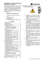
Description of systemSystem functionsmetermetermetermetermetermeternetwork nodenetwork nodenetwork nodenetwork nodeGatewayGatewayGSMGSMRS232RS232billingbillingcontrolcontrolmetermetermetermetermetermeternetwork nodenetwork nodenetwork nodenetwork nodeM-Bus (cable)EthernetEthernetinformationinformationotherservices otherservicesin flatcommunicationin housecommunicatinautomatic meter readingRemote datatransmissiondata processingThe Siemeca AMR system is for wireless remote meter readingfor consumption (meters) devices in the household and commercialbuildings.For this purpose, it contains a number of consumption (measuring)devices that transmit the acquired data to the network nodes severaltimes a day. The individual network nodes receive and store thedata and distribute them throughout the network.We offer a gateway for remote readout that provides the consumptionvalues of all (meters) devices for remote data transmission.6 • Safety notes and description ofsystemSiemeca AMR
consumption measuring devicesconsumption(measuring) devicesThe consumption (meters) devices are as follows:• heat cost allocator WHE26...• water meter WMV26... (measuring capsule) and WFV26...(single-jet)• heat meter WMM26... (measuring capsule) and WFM26...(single-jet)• heat/cold meter WMM26... (measuring capsule) andWFM26... (single-jet)• impulse adapter AEW36.2 for integrating external meters withimpulse outputThe consumption meters transmit the readout data several times aday. The network nodes receive these data telegrams and storethem.Siemeca AMR Contents • 7
Network nodes WTT16 and WTX16functional descriptionThe network nodes WT..16.. form the actual radio network, thatreceives, processes and provides the user of theSiemeca radio system with the data that are transmitted fromthe individual meters for readout purposes.In order to meet the various requirements, different network nodesare available:network nodes • network nodes with battery supply WTT16• network nodes with mains supply WTX16• network nodes with different external communication interfacesWT..16.....types:applicationBatteryoperatedMainsconnectionstandard WTT16 WTX16with RS232 interface for localdata readout WTT16.232 WTX16.232with Gateway for remotereadout via GSM -- WTX16.GSMwith Gateway for remotereadout via Ethernet -- WTX16.IP8 • Safety notes and description ofsystemSiemeca AMR
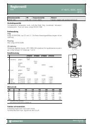
every network node hasthe entire data stock!remote datatransmission via GSM orEthernetOne or several WT..16.. form a network. Every network nodeWT..16.. receives the data telegrams of the meters within its receptionradius. All network nodes WT..16.. exchange all consumptionvalues within this network to ensure that each WT..16.. is in possessionof all information, i.e. all consumption values of all meters.These data can then be read out locally with the PC radiomodule or via the M bus directly from the network node that is theeasiest to reach.A network node WTX16.GSM can be used at any point in thenetwork for reading out via the GSM network or a WTX16.IPwith Ethernet interface. This network node that is capable of remotereadout requires a mains voltage supply.s3sThe consumption values of the meters are received (either directlyfrom a meter or from another network node) and distributedthroughout the network by the transmitter.s4The memory in the network node is for storing the consumptionvalues.network21sAfter all the network nodes have been installed, they independentlyform a network in which each individual network node is integratedvia at least one radio link.The illustration on the left demonstrates the principle of such anetwork.Although individual network nodes do not (cannot) directly communicatewith all the other network nodes in the network, the consumptionvalues (readout data) arenevertheless made available at all other network nodes.For example in the illustration, the network node receives theconsumption values that were received from via the networknodes and .Siemeca AMR Contents • 9
ief installation descriptionThe following is a brief description on how to install the completesystem.It contains only information that is necessary for understanding thesystem.A detailed description of installation can be found in the systemmanual.10 • Safety notes and description ofsystemSiemeca AMR
planningThe following points must be known before commencing installationof a radio system:• number of (measuring) devices,( = meters)• spatial expansion of the building,• propagation conditions,• number of network nodes required, etc.The first step is always the planning.The extent of the planning depends more or less on the size of theplanned system.A plan (layout) of the building is always helpful to determine thepositions for the network nodes.Each (meter) device must be received by at least one network nodeand each network node must be capable of reaching at least oneother network node in the network.Siemeca AMR Contents • 11
installation of the network nodesAfter planning, the positions for the network nodes are established.Usually the network nodes are installed first.For installing battery-operated network nodes, insert two plugs tosecure the housing of the network nodes.After installing the first network node, set the so-called installationmode by pressing the red MODE key. The network node thenchecks first whether other network nodes are already in the receptionrange.If this is not the case, this device (first) is allocated the networkaddress 01, as well as an unambiguous four-digit network number.During the installation phase, this first network node has the specialtask of allocating all further addresses. After installation, allnetwork nodes in the network have equal priority and each nodereceives the same information.After the second network node has been installed and set in the installationmode, it searches for further network nodes in the receptionrange.In this case it will find the already existing network node fromwhich it will receive a new device number and the already determinedunambiguous network number.Installation continues in this manner until all network nodes are installed.The installer only has to press the MODE key, no further operationis required.The status in the network can be checked at the LCD of the networknodes.12 • Safety notes and description ofsystemSiemeca AMR
mounting and installation of measuring devicesOnce a network has been installed, the (meters) devices can be installedin the same manner as conventional devices:The (meter) device is mounted at the intended site by the fitter. Thedevices log into the network automatically by transmitting installationtelegrams in the network. Heat cost allocators transmit theseinstallation telegrams automatically after closing the housing (forthis reason, it is important that the housing remains open before installation!).Other meters require the activation of keys at the device to transmitinstallation telegrams –further operation however, is unnecessary.After all devices have logged into the network, the system is basicallyready to function.Installation is completed manually (by repeatedly pressing the redkey MODE at a network node) or automatically after 8 hours.Every device transmits current measured values and due date valuesto the network.The network nodes exchange the received measured values andthus ensure that at all measured values are available at every networknode within the network.The system is now ready for operation.The commissioning file is saved with the aid of the ACT26 software.Save this file carefully – you will need it for restoring the devicelist (directory) in a network node in case of an error. (see page66).Siemeca AMR Contents • 13
The PC radio ModuleapplicationsThe PC radio module can be used aloneor in conjunction with a laptop and the readout andcommissioning software ACT26 for the following applications:• project planning of Siemeca AMR systems as well astesting the technical RF characteristics of buildings• monitoring commissioning of Siemeca AMR systems(with ACT26)• fault diagnosis and administration of Siemeca AMR systems(with ACT26)• wireless readout (with ACT26)The applications with ACT26 are explained in the description ofthe software.14 • The PC radio Module Siemeca AMR
setupon/offholdCPU,memoryThe PC radio module comprises the following modules:• a transmitter and a receiver for 868 MHz enable communicationwith the Siemeca AMR system• a USB interface enables the PC radio module to be connectedto a PCreceiver, transmitter2 x AA(1,5 V)USBinterface• the supply voltage for operation with connection to a PCvia two batteries Type AA; current is supplied to the USBport of a PC via this connection• two control buttons and a display enable the use of the PCradio module for field strength measurementsSiemeca AMR Contents • 15
Supply voltageThe PC radio module can either be powered by two batteries TypeAA (Mignon) or by connecting to a PC or laptop via the USB connection.battery supplyLoosen the two screws on the back of the PC radio module to accessthe battery compartment that holds two batteries or accumulatorsType AA (Mignon).We recommend using alkaline manganese batteries or nickel hybridaccumulators to ensure a long service life of the PC radiomodule.The correct polarity of the batteries is marked in the battery compartment.supply via USBThe PC radio module can be connected to a PC or a laptop withthe USB cable that is included in the scope of delivery of the PCradio module set. When the laptop is switched on, the PC radiomodule is ready for operation.Details on connection and installation of the PC radio module canbe found in „connection of PC radio module“ on page 27.16 • The PC radio Module Siemeca AMR
Operationon / offpress for 2 seconds!holdThe PC radio module has two buttons for manual operation:„on/off“ Press this button to switch the PC radio moduleon/off. A switch-on delay avoids incorrect operation.Therefore, press the button longer than two seconds until the deviceis switched on/off.„hold“ Keep the button pressed to retain the device that hasjust been received in the display (normally the display is onlyvisible for a few seconds to show the devices in chronological order).After releasing the button, information is displayed that has beenreceived in the meantime.The display contents change cyclically when the „hold“ button ispressed:The display at the left shows the device number of the (measuring)device that has just been received.The number of bars above and below the digits show the data signalquality detector.This display alternates with the display above.It contains further information on the device that has just been received:This display shows the relative reception level in therange between 0 and 255.This display shows the relative noise level in the rangebetween 0 and 255.Siemeca AMR Contents • 17
Instead of displaying a measuring device number (in the top illustration04999118), this display can appear near to already operatingradio systems.This is the display for a network node (in this case, the networknumber 2010 and network node 1).The number of bars above and below the digits show the data signalquality detector. Press the „hold“ button to display informationon the signal and noise level.Two arrows can appear via the 8-digit display that denotethe ready-to-receive state /or an existing USB connection.18 • The PC radio Module Siemeca AMR
Project planning, field strength measurementIn conjunction with the supplied keyboard transmitterWHE26.DEMO, it is possible to check the propagation characteristicsof buildings and to determine during the planning phasewhether safe connections can be established between (meters) devicesand network nodes or between the network nodes themselves.keyboard transmitter WHE26.DEMOThe keyboard transmitter WHE26.DEMO has four different operatingmodes that can be activated via the button on the front of thedevice:transmitter is deactivated:This state is automatically reverted to after an hour intransmit mode.transmission of installation telegramstransmission of data telegramstransmission of statistical telegramsThe selected telegrams are transmitted twice per minute.For measuring the field strength, the telegram AdatH is recommendable.For other tests in existing radio systems, it may be of assistance toselect another type of telegram.Siemeca AMR Contents • 19
field strength measurementThe objective of this measurement is to determine whether the(meters) devices can be received by network nodes at a specificposition.For this purpose the keyboard transmitter WHE26.DEMO isplaced at the furthest point or critical points in the planned receptionrange of a network node and activated by pressing the buttontwice. Its display then indicates AdatH .The PC radio module then checks whether the field strength at theintended installation site is adequate for reliable reception.In order to assess the reception field strength, bars are displayedabove and below the device number in the display of the PC radiomodule.This display can be interpreted using the table on the front of thedevice. If a keyboard transmitter WHE26.DEMO is used, use onlythe left column of this table for estimating the strength.Only use the right column when a network node WT..16.. is usedas a test transmitter.20 • The PC radio Module Siemeca AMR
field strength assessmentno bar:The field strength is inadequateone bar: The field strength is weak; interruptions in communicationbetween the (meter) device and the network node arepossible.This field strength is still inadequate for communication betweentwo network nodes.two bars: The field strength is good. Interruptions in communicationmay occur in special circumstances.three bars:The field strength is very good.four bars: The field strength is above average; the transmitteris in the near-field region.In order to ensure that the Siemeca AMR system functions reliably,every (meter) device that is being installed must indicateone or two bars.Too low reception levels can result in installation problems, interruptionsin communication between the network node and (meter)device after installation and in the worst case, to a permanent interruptionin communication.Siemeca AMR Contents • 21
Installation and set-up of the softwareACT26General overviewThe commissioning and readout software ACT26 can be usedfor the following purposes:installation Siemeca AMR systems, installation monitoring,reading and writing commissioning fileslocal readout of Siemeca AMR systems via M-Bus, RS-232or wireless with the aid of the PC radio moduleexchange of device, deleting individual devices or completedevice groupserror detectingSiemeca AMR Installation and set-up of the software ACT26 • 23
System conditionsThe software ACT26 requires a PC with the operating systemWindows®98 or Windows®2000.It requires 10 MB fixed-disk storage.The PC or laptop must be equipped with the PC radio module witha USB interface for operating the ACT26. The PC radio module issupplied with voltage by the PC.For the local readout of Siemeca AMR systems via theM-Bus, the PC must be equipped with a serial interface RS232(COM). The following accessories are also required:only for local readout ofWT..16.232local readout of anyWT..16..RS 232 cable WTZ.K232Programming adapter: M-Bus Minimaster WFZ.MBM24 • Installation and set-up of the software ACT26 Siemeca AMR
Installationinstallation of softwareInstallation of the commissioning and readout software will usuallycommence automatically after inserting the CD ROM (activatedautostart).Should the autostart not function, please start installation as follows:Click „Start“ and select „Run“ to start manually.Enter the following in the entry line:X:setupThis entry line contains „X“ for the drive letter of your CD drive.Change this letter accordingly. Click OK .After autostart or after manually starting installation as described,the InstallShield Wizard opens. This program copies the softwareonto the PC.Follow the instructions on the screen. Alterations are normally notrequired.Click the next button to open the next window. Click theback button to return to the previous window.You must agree to the licence conditions.Choose the option:„I accept the terms...“Siemeca AMR Installation and set-up of the software ACT26 • 25
Change the installation path.The standard path is:C:\Programs\Siemeca\ACT26On completion of the installation program, click finish ; thesoftware ACT26 is now installed on your PC.The following directory is standard.C:\Programs\Siemeca\ACT26How to change the storage location for the data is described onpage 31.26 • Installation and set-up of the software ACT26 Siemeca AMR
connection of PC radio moduleWhen connecting the PC radio module to the PC for the first time,two (!) drivers are installed.The following instruction describe the installation of the driversunder Windows® 2000.The dialogs vary under other versions of the operating system, butthe procedure remains basically the same.Connect the PC radio module and a USB port of your computer tothe supplied cable.You will usually find one or more ports on the back of your computer.After connecting the PC radio module for the first time, the Windows®hardware assistant will indicate that it has found a new device.If this does not occur automatically, click the hardware icon in thesystem control and start a search for the device.The installation assistant then starts.Choose the option „find a suitable driver“.Siemeca AMR Installation and set-up of the software ACT26 • 27
If the installation assistant requests the source for the driver files,choose „state other source“.In the next window, you are requested to choose the source forcopying the drivers.The drivers are on the program CD or the fixed disk of your PC ifyou have already installed the software.Click „search“ to open the window with a directory tree. Choosethe folder:• C:\Programs\Siemeca\ACT26\Drivers or• X:\Drivers („X“ stands for the drive letter of your CDdrive)Click „open“.The source for the driver installation appears in the entry line.Click „OK“.Windows® will find a suitable driver for „USB Serial“.Click „next“.The driver is now copied.Confirm by clicking „finish“.28 • Installation and set-up of the software ACT26 Siemeca AMR
Windows® then announces that new hardware, a USB serial porthas been found.Proceed as described above.The required drivers are in the same directory on the fixed disk oron the CD.You will now find a new entry USB serial port in the devicemanager with the automatically allocated COM port number.In case the automatic search routine of ACT26 software does notfind the PC radio module, the COM port number can be found inthe device control and entered manually in the program.Siemeca AMR Installation and set-up of the software ACT26 • 29
Initial startBefore using this software, a few simple preparations are required:setup of PC radio moduleAfter starting the software ACT26, a login window appears.When starting for the first time,click „cancel“ instead of logging in.error message when loggingin without PC radiomoduleShould you, nevertheless, login when starting the software forthe first time, the error message on the left appears, indicatingthat the PC radio module is not yet installed.Acknowledge the window “error” with click OK .Close the window „connection” by clicking the button X in thetop right corner of the window.To install communication with the PC radio module, open the menu„extra“ ( + ) andactivate „link via...“.This can also be achieved by clicking the button or by clicking this symbol.To choose the type of connection to the network (M-Bus, serial orradio), you have to close the window „connection “ !30 • Installation and set-up of the software ACT26 Siemeca AMR
A window opens:choose radioand click settings .In this window, you can see the COM port that is required for thePC radio module.If you do not know the port, click detect USB port and itcan be determined automatically.After a successful search, the settings window closes automatically.If the search was not successful, you can determine the reservedCOM port in the device manager (see page 29).determine storage locationWhen data is read out of the network, they are stored in a specialfolder.The name of this folder contains the number of the network. Example“...LSE_DATA\NW_2440”if you readout network 2440.These folders are filed in the directory:C:\LSE_DATAEnter the usual storage location for your billing data, e.g.:D:\Billing\Siemeca_DataSiemeca AMR Installation and set-up of the software ACT26 • 31
file dataOpen the menu „extra“ and choose „link via...“(alternatively with +, ).The window on the left appears. You have two possibilities:1. you have already created a new folder in explorer. Choosethis folder in the window. The path is displayed in the entryline.2. enter the new path manually in the entry line:e.g. D:\Billing\Siemeca_Data.If the folder does not exist, it will be automaticallycreated.Confirm with OK .This path will now be offered when saving.You can, of course, choose another folder.loginFor the first run of the software, you have to login as administrator.Open the menu „connection“ and click „login“.You can also use the key orthe keyboard shortcut +, .As authorisation choose „administrator“, user is „ADMIN“ andfor the password also enter „ADMIN“(without inverted commas ! ).If you exit the program, all changes that you have made,will be automatically saved andare available when you call the program again.32 • Installation and set-up of the software ACT26 Siemeca AMR
Working with the software ACT26IntroductionThis chapter is concerned with how to solve a specific problem.The readout sequence is described first and then the installation and diagnosis of a radio system (from page 34 onward).At the end of this chapter, a number of settings and special features are described that are not applicable to theabove-mentioned sequence (from page 100 onward).Siemeca AMR Working with the software ACT26 • 33
Login and LogoutThe software demands a login immediately after the program hasstarted. This authorizes you as legal user of this system and preventsmanipulation by unauthorized persons.loginIf you have a newly installed system, you can always login withthe standard user name „ADMIN“ and the password „admin“.If you have defined other users, you can, of course,login under this user name (see page 58).In the „login“ window, you can choosethe options „keep user“ and „keep password“.With this option, the software automatically suggests the chosenuser name after the next program start.You can change the user name at all times.Both the user name and the password should notexceed 6 characters. Only capital letters are used.However, should you enter small letters, these will be automaticallychanged to capital letters.You can use the following characters:„A…..Z“; „0…..9“; „_“ and the blankAfter logging in, the user name „ADMIN“ and the user level„administrator“ appear in the footer of the program window:switch to user levelYou can login at all times even when already connected to switchto the user level.Siemeca AMR Working with the software ACT26 • 35
To login again, choose „login“ ( + , or ) in themenu „connection“.Enter the new user name in the „login“ window.If you have already done this, this name will appear in the list thatyou reach via the button next to the input window „username“. Otherwise click the input window and enter the new username via the keyboard.The user name then appears in the footer of the program window asconfirmation, e.g. „NEUADM“, and the user level „administrator“:Ensure that you enter the correct password for the user name andalso choose the correct authorisation.choose correct user authorisation!Should you login with an invalid user name or password, or shouldthe user name not match the authorisation,you will not immediately receive an error message.However, later when you wish to access a network (double click anetwork node in the window „connect“),access will be refused and the error message on the left appears :„Access denied. Check entries in the login window ! “logoutWhen you logout, the user rights are reset to guest (state beforelogin). Logout is not compulsory.Choosing a networkAfter login, the window „connect“ opens automatically.This window you can also re-open with the menu „connection“ /connect„connect“ ( + , or )or by clicking the symbol on the left.36 • Working with the software ACT26 Siemeca AMR
When you are correctly connected to one of the types of connection• radio• M-Bus• serial(see page 30,34), the window “connect” opens anddisplays one or several network nodes depending on the connection.If you connect your PC with a programming adapter WFZ.MBMor with a serial connection via the special cable WTZ.K232 to anetwork node, only a connection to the relevant network node ispossible and only one network node will be displayed in this window.If you use the PC radio module, all network nodes in the radiorange will be displayed after a brief waiting period(usually 2 minutes).This enables you to choose e.g. the network node with the best receptionlevel in the desired network.In case you readout the entire M-Bus line, all devices directly connectedto the M-Bus will be displayed.Every network node stands for a separate network.Siemeca AMR Working with the software ACT26 • 37
Connection to a networkYou still have no connection to the network.To connect to a network node,double click the desired network node in the window„connect“.Choose the network node via the keyboard using the cursor andthen press to open the desired network.The network node that is used to create the connection thenappears in blue.If the connection has been set up successfully, a green dot appearsin the state bar which indicates that you are connected to the network.Also the current network structure is automatically displayed in thewindow „Network“ immediately after connection has been set up.However, you can only open a connection to one network. Furthernetwork windows can be displayed on the screen but older onesare no longer active.38 • Working with the software ACT26 Siemeca AMR
Readout• In order to readout a network, the PC must first be connectedto this network.For this purpose you can choose between three types of connection(see page 30, 34).• radio• M-Bus• serialWhen the connection has been set up, the window„network“ appears on the screen and the status bar indicates„ready-to-receive“ with the green symbol.In order to read out the network, enter themenu „data / read data“(or activate + , or ).You can also click with the mouse on the button illustrated below:The window „readout data“ then opens and readout commences.After all data have been transmitted, the values can be found in thewindow „readout data“:Siemeca AMR Working with the software ACT26 • 39
Contrary to other standard windows, this window has its ownmenu bar.Different forms of representing the readout data are possible in thewindow “readout data”.The data can also be saved in different readout formats.The setting you make remains valid!40 • Working with the software ACT26 Siemeca AMR
Readout formatsThe software ACT26 uses three different formats for readout files:• *.REP readout filesThis format was already supported by the first versions ofthe ACT26.Compare the point description on page 142.• *.BIL readout filesThis format became available with version 1.2.It contains some additional points.Compare description on page 132.• *.XML readout filesThis format also became available with version 1.2.So far, it has only been supported by the ACS26, the remotereadout software for network nodes with Gateways. Comparedescription on page 137.Siemeca AMR Working with the software ACT26 • 41
Choose readout formatBasically, you can change the readout format, in other words, theformat in which you save the data, with every readout.This means that the PC must be connected to a network and thedata must have already been read out to determine the readout format.As a rule, you will only want to determine the readout format onceso that you can always save the same format.To make this one-time setting, the PC must be connected to a networkand the consumption values must have been read in once.In the previous section, you have learned how to connect to a networkand how to readout data.The presentation of the readout data is always the same; the formatof the saved data, however, can vary.To determine the data format of the readout file, choose in themenu „extra“, the option „format readout file “.A window opens with different options:The following settings are possible:42 • Working with the software ACT26 Siemeca AMR
file format -(XML or ASCII)definitionXML: Short for “Extensible Markup Language”;XML is a universal concept for saving data and therefore not restrictedto the Internet and WWW.We use this format to be able to provide a universally applicablereadout format for future purposes.ASCII: Short for »American Standard Code for InformationInterchange«. This standard encodes the most common charactersby an 8-bit sequence of numbers.The ASCII files are simple text files in which the individual datapoints are separated by tabulators.If you decide on XML or ASCII, you are basically choosing theformat for the readout file:ASCII comprises the *.REP and *.BIL files that are compatiblewith the old remote readout systems of Landis & Staefa.XML stands for *.XML files.table format - (OZW10 or OZW20)This type only affects the number of data points in both ASCIIformats.If you have chosen the XML as file format, this does notaffect the output format.If you choose OZW10 under„table format“, the readout file willbe a *.BIL file;if you choose OZW20, the readout file will be a *.REP file. Bothfiles are text files (ASCII), that only differ slightly in their datacontents and in the layout of their data.The *.BIL format (OZW10) hasSiemeca AMR Working with the software ACT26 • 43
more points than *.REP format (OZW20).table header - (OZW or plain text)This choice only affects the column headers in both ASCII formats.XML files are not affected by a setting in this section of the window.If you choose under „table header“ the OZW format, all columnheaders will include abbreviations, otherwise,the column headers appear in plain text.44 • Working with the software ACT26 Siemeca AMR
for example :plain textdateday of weektimeoperating hoursOZW formatZDat305ZWt306ZUhr306CBS304A complete format description can be found from page Fehler!Textmarke nicht definiert. onward.please note:You only receive readout files that are compatible with the formatdescriptions from page Fehler! Textmarke nicht definiert. onward,if you choose the file format ASCII in the window „formatreadout file“and under “table format” the OZW type.You must also not use the filter functions offered in the window„readout data“, as this may result in complete columns beingblinded out.Siemeca AMR Working with the software ACT26 • 45
forming standard file namesThe standard names of the readout files are formed as follows:yyyymmddhhmm.fffThe standard name is formed from the• year, month and day (yyyymmdd),• hours and minutes (hhmm) and• with the following file extensions (fff):XML or REP or BILsave readout dataIn order to save the readout data, choose „file / save file“.Keyboard shortcut: + , save before editing thereadout file!storage pathimportant:If you save readout data, the data that are displayed on the screenare saved.This means that the you should save the data before changing thescreen shots described in the following chapter.Otherwise, information that is not displayed is not saved in the file!You already determined the location for storing files when thesoftware was started for the first time.Compare page 3146 • Working with the software ACT26 Siemeca AMR
Working with readout filesThis section describes individual procedures for working withreadout files.change column headers in device listThe column headers can be switched between plain text and the(standard) abbreviations of the defined OZW format.A complete overview of the headers, designations and contents ofthe readout files in OZW format can be found in the annex. Examples:SFunkDev ... network nodeZDatR233 ... readout dateZuhrR234 ... readout timeThe column header with plain text is set !sort dataIn order to sort the readout data according to specific criteria, clicka column in the corresponding “table header”.Click further to choose between sorting upward or downward.E. g. here the list of the received network nodes is sorted upward.In order to create the original sequence, sort the first columnheader „number“.Siemeca AMR Working with the software ACT26 • 47
searchStart the search function in the menu „edit / find“.(here is themeaning of find = search)It is useful when searching for special data, e.g. the identificationnumber „4501824“.If the search is successful, the desired cell next to the search windowis highlighted in blue.copyWith function „copy“, all visible values in the table can be copiedinto the clipboard of Windows®.The data can then be imported to other programs e.g. Excel for furtherediting.When the filters are activated, only the displayed data will beadopted!48 • Working with the software ACT26 Siemeca AMR
choose individual columnsIn order to simplify matters, individual columns can be activated.Click „extra / select columns“or the keyboard shortcut : + , A new window opens that contains all the column headers. Choosethe column header you require.Then click OK and the chosen column headers appear on thescreen.In the dropdown menu under „view“, „selected columns“ is automaticallyactivated.To display all the column headers again, deactivate the menu item„selected columns“.Or the keyboard shortcut:before saving, deactivate„select column“ !! + , important:When the readout files are stored, the data that appears in thescreen is saved.As far as the selected columns headers are concerned, this meansthat only the „selected (measured) data” are stored.Deactivate the filter before storing all (measured) data.Siemeca AMR Working with the software ACT26 • 49
select rangeYou can select a specific range (for example. any lines) using themouse.If you choose „select range“ in the menu „view“, only the markedrange appears on the screen.Keyboard shortcut : + , before saving switch off„select item“!important:When the readout files are saved, the data that appears in thescreen are saved.As far as the selected ranges (lines) are concerned, this means thatonly the „selected“ (measured) data are saved.To save all measured data, you have to select before„view / all“ !50 • Working with the software ACT26 Siemeca AMR
Filter table entriesIf you wish to search large readout files according to specific criteria,this function helps you to filter the data according to one orseveral criteria, e.g. faulty devices or low consumptions:numbernw node = network nodereadout datereadout timedevice IDmanufacturersoftware versionerror codeerror dateerror timecumulative energydim. cum. energycumulative volumedim. cum. volumemediumenergy on set daydim. energy on set dayset daystatistic datestatistical value 1 …18dimension of statisticstariff1 valuedim. tariff1 valuetariff1 value on set daydim. tariff1 value on set daySiemeca AMR Working with the software ACT26 • 51
The sorting criterion can also include whether it is equivalent,smaller or greater than the freely selectable value.For example:criterionnetwork node = 1devices ID > 12345678resultdisplays all (meters) devices in networknode 1displays all (meters) devices with anID greater than 12345678max. three criteria can be combined.criterionnetwork node = 1ANDmedium = 8resultdisplays all (meters) devices in networknode 1 ANDMedium = 8, i.e. all heat costallocators in network node 1medium = 6ORmedium = 7displays all (meters) deviceswith a medium equivalentto 6 OR 7, i.e. all cold and hot watermeters.Activate the filter with the following keyboard shortcut: + , If you have defined a filter, it will be applied to the readout file.„filter“ is then automatically activated under „view“.52 • Working with the software ACT26 Siemeca AMR
medium = 7ORmedium = 8would thus display a readout list that only contains water meters.before saving, deactivatefilter !In order to display all devices again, deactivate the filter in themenu „view“.important:If you save readout files, the data that appears in the screen aresaved.As far as the filter is concerned, this means that only the„filtered“ measured data are stored.Always deactivate the filter before storing all measured data.After use, the filter can also be saved in the menu „file“: + , Name the file as desired. The file extension is „FLT“. (FILTER)Reload saved filters in the menu „file” : + , Siemeca AMR Working with the software ACT26 • 53
Monitor installationTo avoid confusion as regards already installed devices,we recommend logging the entire installation procedureon the PC.Use the installation log in conjunction with a PC radiomodule that is connected to the PC for this purposestart the installation log via themenu „diagnosis / installation log“.alternative : + , or Installation is as follows:• the (meter) device transmits installation telegrams. The installationtelegram is received directly by the PC radiomodule and displayed on the screen highlighted in red.• a network node also receives the installation telegram. The(meter) device is identified as a new device and entered inthe device list of the network node. Shortly afterwards, thisinformation („receive new device“) is transmitted throughoutthe network.• The PC radio module also receives this information andchanges the colour of the highlighted device to green.54 • Working with the software ACT26 Siemeca AMR
In order to receive the installation telegrams directly from the PCradio module, the (meter) device must be within the reception radiusof the PC radio module (15 to 25 m).If this is not the case, the installation telegrams highlighted ingreen will be displayed immediately and not the red ones. This informationis received from the nearest network node. It clearlyconfirms that a new device has logged into the network.The window „installation log“ provides information on how to usethe displayed data:• save of installation logs• open already saved installation logs• delete devices (meters)• refresh devicesAll these functions are reached via the context menu that is openedby clicking the right mouse button on a line inthe window„installation log“.Siemeca AMR Working with the software ACT26 • 55
save installation logsAfter clicking the window and closing the window„installation log“you can save the device list for your documentation orfor subsequent use.A file name yyyymmdd.LOG is suggested.This name comprises the year, month and day.The LOG file is stored in your data folder sub-folder „LOG“ whennot otherwise stated.open already saved installation logsThis function is useful if you wish to continue with the work fromthe previous day and wish to view the already installed devices onthe screen.56 • Working with the software ACT26 Siemeca AMR
delete devices (meters)By deleting, „irrelevant“ (meter) devices that are unintentionallydisplayed, are removed from the screen.note:Deleting at this point does not affect the device list.Therefore, if the „irrelevant“ (meter) device is highlighted ingreen, it must also be deleted from the network!refresh devicesSelecting this function, induces the corresponding network node tore-transmit an „acknowledgement telegram“ for this device so thatdevices unintentionally highlighted in red on the screen arechanged to green (=received).note:If “refresh devices” is not successful, you can assume that the (meter)device was not installed.In this case release new installation telegrams!Siemeca AMR Working with the software ACT26 • 57
Create user accountsThe user concept is explained on page 123 where you will find instructionson how to proceed.important:In order to prevent „your“ network from being read outby unauthorized persons from the street, the standard account thathas been created „ADMIN“ must be deleted!create a new administratorCreating a new administrator is carried out in two stages.You must first create a new account beforedeleting the old one.login:In order to create a new administrator account, you must first loginor already have logged in with the standard user name „ADMIN“and the password „admin“.Acknowledgement of the user name „ADMIN“ and the user level„administrator“ appears in the footer of the program window.Set up a connection to the network for which you wish to create anew administrator (double click the network node in the window„connect“).58 • Working with the software ACT26 Siemeca AMR
user list :In the menu „plant directory“ (system directory) select „user list“.alternative + , A small information window then opens with :„read user list“.create a new user:As soon as the user list is downloaded from the network, it is displayedon the screen.For a newly installed network under number 1, it shows the user„ADMIN“, with the authorisation of an „administrator“.Click the second line with the mouse and then change .An input window “password” appears.Select under authorisation„administrator“and enter a new user name under user name.In the example, „NEUADM“ was selected for both - the user nameand the password. You can, of course, choose the name for theuser and password you wish.The password is not displayed for security reasons. For this reason,you must enter the password in both entry fields.Siemeca AMR Working with the software ACT26 • 59
Ensure that both passwords are identical.In case of an error, the error message on the left appears.The user name and the password have a maximum of sixcharacters. Only capital letters are used.Small letters are automatically changed to capital letters.You can use the following characters:„A….Z“; „0….9“; „_“ and the blank.If all entries were correct, two users appear in the list: „ADMIN“and „NEUADM“.Close the window by either clicking closeor the button X in the top right corner of the window.You must now login again as the account with which you have justlogged in, cannot be deleted.60 • Working with the software ACT26 Siemeca AMR
new login:To login again, select the item „login“ in the menu„connection“or( + , or ).Enter as user name „NEUADM“ and as password „NEUADM“ orthe new name that you have chosen in the „login“window,.The user name „NEUADM“ and the user level „administrator“ appearin the footer of the program window as confirmation:delete old user account:Choose „user list“ in the menu „plant directory”Alternative : + , Mark the line 1 (user name „ADMIN“)and click delete .Click yes to acknowledge„Are you sure to delete account ?“ andthe new user list is then written.(This is the same like “write user list”)The old account for the user „ADMIN“ is now deleted.Siemeca AMR Working with the software ACT26 • 61
no access!If you now wish to access the network with theuser name „ADMIN“ and password „ADMIN“ (doubleclick a network node in the window „connect“),access will be denied.create a new userIn order to create a new user, you must have logged in with theuser rights “administrator“ .Set up a connection to the network for which you wish to create anew user (double click a network node in the window „connect“ ).To create a new user account, select the item „user list“ in themenu „plant directory .Alternative : + , A small information window opens „read user list“.(this is the same like “reading security table”)create a new user:As soon as the user list has been loaded from the network, it appearson the screen.As a rule, it shows a user that has the authorisation of an „administrator“.In the example on the left, this is a newly created user„NEUADM“.Select a free line with the mouse and click change .62 • Working with the software ACT26 Siemeca AMR
A window „password“ appears.Select „Nutzer“ under authorisation andenter a new user name under „user name“.The user name always appears in capital letters and can have amaximum of six characters.„NUTZ01“ was entered in the example.You are of course, free to choose the desired user name.Enter a password and re-enter it in the last entry field.In the example, „nutz01“ was entered as a password.The password can comprise digits, or small or capital letters. Thepassword length is limited to six characters.Ensure that the two entered passwords are identical.In case of an error, the error message on the left appears.If all entries were correct, two users appear in the list: „ADMIN“with administrator rights and„NUTZ01“ with user rights.Close this window by either clicking close orthe button X in the top right corner of the window.Siemeca AMR Working with the software ACT26 • 63
delete a userIn order to delete a user, you must have logged in with the userrights „administrator“.Set up a connection to the network in which you wish to delete auser (double click the network node in the window „connect“).To delete a user account, select the item „user list “ in the menu„plant directory“ (system directory).alternative : + , A small information window opens „read user list“.(This is the same like “Reading security table”)delete user:As soon as the user list is downloaded from the network, it appearson the screen.Select the user that you wish to delete with the mouse and clickdelete .You will then be asked whether you wish to delete the user:„Are you sure to delete account ?“If you confirm with yes, the user is deleted.You can now close the window „user list“with either closeorX in the top right corner of the window.important:64 • Working with the software ACT26 Siemeca AMR
You cannot delete your own account with which you are logged in!If you wish to delete your own account, you must loginbeforehand under another name (the name entered as administrator)!Siemeca AMR Working with the software ACT26 • 65
Read and save commissioning fileread commissioning fileThe commissioning file is the plant directory that contains all the(measuring) devices in the network.important:In order to have a device list of the installed system available incase of an error, a commissioning file should be saved and storedafter every installation or change made to the plant directory.Set up a connection to the network !Access is via the menu „plant / plant directory“ .alternative: + , or You can also click button illustrated below with the mouse:The window „plant directory“ opens.Click the button read from nw node .The data are transferred from the network node to the PC and displayedin tabular form:Click save file .66 • Working with the software ACT26 Siemeca AMR
A window appears in which you can change the file name andchange the save the storage location.The suggested standard name for the commissioning file is as follows:commissioning filePLxxxx_yyyymmddhhmm.PLTThe standard name is formed from „PL“ for „plant file“(=commissioning file), the network number (xxxx) year, month,day and time (yyyymmddhhmm) with the file extension „PLT“.The file is filed in the sub-folder „ADMIN“ of the relevant networkfolder.Siemeca AMR Working with the software ACT26 • 67
write commissioning file in the network nodeonly possible with wirejunction!You can load the commissioning file from the fixed disk as requiredand write it in the network node.important:To write in a commissioning file, the network node must be connecteddirectly to the PC, e.g. via a wire junction.The PC radio module cannot be used to write in the commissioningfile.The programming adapter WFZ.MBM can be used to connect anM-Bus connection to any network node.With the network nodes, type WTT16.232 and WTX16.232 youcan also create a serial connection via the RS-232.Access is via the menu „plant / plant directory “,alternative : + , or You can also click the button illustrated below with the mouse:The window „plant directory“ opens.Click the button read from file .You can now select the corresponding folder and open the desiredcommissioning file.(Only files with the extension „PLT“ are displayed.)The devices of the plant appears.Click the button write to network node .A new device entry is now created for every new device in thenetwork node.68 • Working with the software ACT26 Siemeca AMR
startup file is added to existingdevice folder!write startup file in all networknodes!NW node 0important:When you import the commissioning file again in a new networknode, the new devices will be added to the existing folder !If you only want the devices that are entered in the commissioningfile in the network, you must reset the network nodes to the factorysetting (see annex on page 134).Import the commissioning file and set up the network again (installationmode !).important:Every network node has a plant directory of the installed devicesand exchanges this information with other network nodes.If you import a new commissioning file only in one network node,the (measuring) devices will only be received by this networknode.It is, therefore, important to load a new commissioning file inevery network node of a network !As the newly transferred devices have not been received by a networknode, the devices are allocated to the temporarily fictitiousnetwork node „0“.Later, when all devices have been received, the (measuring) deviceswill be allocated to a real network node.The network node „0“ then no longer appears in the device list.a new system directory requiresthe extended searchmode!important:If you have imported a new commissioning file, the network nodemust first „learn“, when these new devices transmit.For this purpose, you must start the extended search mode afterinstallation (see also page 82).Siemeca AMR Working with the software ACT26 • 69
Edit the commissioning fileIf configuration of the network was changed after commissioning,it may be necessary to manually adapt the plant directory and/orthe commissioning file.Please observe instructions to avoid faults in the network.The plant directory can be changed in the window„plant“.The special feature of this type of change is that changes to thenetwork only become effective when the commissioning file is reimportedin the network node.You have the following possibilities:sort the table entriesClick a column header to sort the table entries in ascending or descendingorder. This can help you to find devices.70 • Working with the software ACT26 Siemeca AMR
delete and insert devices (meters)To delete, select a line. The corresponding line appears in blue.Click delete meters .commissioning file does notdelete devices in the networknode!The device is removed from the commissioning file.Important: When you re-import the commissioning file in a networknode, only the new devices will be added to the existing devicelist !Existing devices are still accessible even if they no longer appearin the commissioning file. If you wish to delete individual devices,use the menu „plant / plant directory /delete meters“ or ( + , ).If you only require the devices that are entered in the commissioningfile in the network, reset the network node beforehand to thefactory setting. (See annex page 134).In order to insert a new device, click first add deviceA new, empty line is inserted in the table.Edit the line as follows:edit a table entryenter all fields correctly ifsystem directories arechanged!Mark the option „edit table“ in the bottom right corner. Click therelevant cell and change the table entry or re-insert.important:When you enter new devices, ensure that all entries correspondexactly with the installed (meters) devices.Otherwise, the devices will not be received by the network node.If in doubt, readout the device number directly from one of the devicesto be installed using the service software.If this is not possible, please contact our Sales Support !Siemeca AMR Working with the software ACT26 • 71
a new system directory, requiresthe extended searchmode!important:If you have imported a new commissioning file, the network nodemust first “learn” when these new devices transmit.For this purpose, start the extended search mode after installation(see also page 82).72 • Working with the software ACT26 Siemeca AMR
DiagnosisUnder the menu item „diagnosis“ you will find a number of diagnosispossibilities for different devices in the network.diagnosisread wireless metersread M-Bus devicesdiagnosis of all wireless metersof the current networkdiagnosis of all connectedM-Bus devices of the currentnetworkread network devicesread all devicesinstallation logsave device diagnosisdiagnosis of all network nodesof the current networkdiagnosis of all devicesinstallation monitoringsave diagnosis fileThe following information can be found in the diagnosis file:• date and time of the last readout• manufacturer (usually LSE = Landis & Staefa electronic)• device identification and serial number• software version of device• device type as code (medium; compare overview on Page128) and in plain text• error code and error date (only applies to major errors)• access number• network number• reception level• network node that has received the corresponding deviceSiemeca AMR Working with the software ACT26 • 73
The example shows a diagnosis of all devices. Depending on theselected menu item,only all transmitting (meters) devices oronly all directly connected (M-Bus) devices oronly all network nodes of the networkcan be displayed.Click a column header to sort the table entries in ascending or descendingorder. This can help you in finding devices.When you close the window, you will be asked whether you wishto save the diagnosis file.A window appears in which you can change the file name and storagelocation if required.The suggested standard name for the diagnosis file is described inthe annex on page 127.74 • Working with the software ACT26 Siemeca AMR
Properties of metersIf necessary, you can open a window “network” for every (measuring)devicee.g. to check the current reception field strengthor an error analysis.Access to the properties of a device is via the device list.Click one of the network nodes in the window “network” withthe right mouse button and a context menu appears.Select „device list“ to open this window.You can also open the device list via key or via the button below:Siemeca AMR Working with the software ACT26 • 75
The device list provides you with information on the device status.Devices that have a temporary error (e.g. interruption in communication),appear in blue, devices with a major error appear in red.If you double click one of the (meters) devices in thedevice list, the window “properties” of this device opens with thepage „state“ :It contains the following information:• current date (and time) of the (meter) device• time of the data telegram received last.There is a clock in both the PC and the (meter) device and bothmay differ from one another.The time can be represented either based on the clock in the deviceor on the clock in the PC.If you click the option „refresh device“, current data will be requestedfrom the (meter) device.If the high-speed mode is active, the data will be updated withinthe next minute. Otherwise, it takes one to two hours until you canaccess the refreshed (updated) information.• error code and description (only in case of an error)76 • Working with the software ACT26 Siemeca AMR
• information on reception in the network (which networknode receives the device, last telegram number and receptionlevel)The last telegram number indicates whether a new telegram hasbeen received by the corresponding (meter) device since the lastreadout.The quality of the radio link can be estimated from the last and averagereception level. The reception level isa relative value between 0 and 250 andshould always be clearly above 50.In the window „properties“ of the device, you also have access toanother page:In the window „device ID“, you will find information onthe manufacturer,device ID, software version anddevice numbers (fabrication no., family no.)Siemeca AMR Working with the software ACT26 • 77
Properties of network nodesYou can recall extensive information on every network node. Thefollowing describes the information that is available.important:You can only receive complete and current information from thenetwork node that is directly connected to the PC (via the PC radiomodule or a wire junction).Information that you receive from the network nodes that are notdirectly connected, contains data from the last communication.Click one of the network nodes in the window “network” with theright mouse button and a context menu appears.If you select „network node“ in this context menu, the window“properties” of this network node appears.You can also open the window “properties” of this network nodeby double clicking the network nodeor via the key or via the button illustrated below:If you select the network node, to which the software is directlyconnected (appears in turquoise in the network window), the window“properties” of this network node appears.It contains detailed information and can be used for changing thenetwork status.Further information can be found on page 121.78 • Working with the software ACT26 Siemeca AMR
If you select another network node, a window “properties” appearsthat only provides information on exactly this network node(device ID and information on the device and reception status).properties of the network node (directly connected to PC)The page „network“ provides information on important networkdata.information on current network statusIn the top left field you can see the network mode (standard, installationor search mode; either normal or extended).Details on the individual operating modes can be found in the systemmanual or in a brief summary in the annex of this description.You can also see the following information in the top left field:• number of (meters) devices• number of network nodes• access interval – how often is opened an access window tothe network in one hourSiemeca AMR Working with the software ACT26 • 79
• update rate – how long does it take until all the data of eachmeasuring device rotate once in the networkThere are three buttons in the top right field:• change mode - switch between individual networkmodes (compare next section)• reset device - separate all network connections of thedirectly connected network node (compare page 84)• restart network – separate all network connectionsin the network and restart this network (compare page 84)information on all network nodesThe bottom field provides information on all network nodes in thenetwork. The columns in the table are allocated to the individualnodes of the network.The lines contain the following information :• high speed transmission – network nodes that are in highspeedmode, are identified here.• network connections – indicates the number of connectionsthat one node has to other nodes• meter connections – indicates the number of measuringdevices that are received by the corresponding node.• battery in % - the remaining capacity of the battery in percent.The network node with the lowest remaining capacityis highlighted.When the lowest remaining capacity falls below a thresholdvalue, it is highlighted in red.Nodes with network supply are specially marked in thisfield.80 • Working with the software ACT26 Siemeca AMR
communication state of network nodeIn the page „network node“ you will find information on the errorstatus(details on types of error can be found in the annex on page 136)and on the status of radio links:• last telegram number• last reception level (in the range between 0 and 250)• average noise level (in the range between 0 and 250)Siemeca AMR Working with the software ACT26 • 81
Change network modeDetails on the individual operating modes can be found in the systemmanual or in a brief summary in the annex of this description.Only the installation mode (red „MODE“ button) can be activateddirectly at the network node.All other changes to the network mode require thesoftware ACT26.You can see the current network mode in the left corner of thewindow “properties” of the network node.Please note that the „checkboxes“ / options, that displaythe current network mode cannot be changed by clicking themouse.In order to change the network mode,click the button change mode .The window „change mode“ appears.Select the desired mode.Combinations of several modes are possible.Confirm the selected mode by clicking OK .to change the networkmode, close the window„properties“ byclicking OK !Important:After closing the window „change mode“, the change in mode hasbeen booked. (The checkboxes / options are marked in grey.)To change the mode, close the window „properties“ of the networknode by clicking OK .Click cancel to reject the change to the network mode.The directly connected network node will change its mode within20 seconds.82 • Working with the software ACT26 Siemeca AMR
Depending on the network mode adopted so far and on the size ofthe network, changing the mode of the entire network may lastfrom a few minutes to two hours.switching the mode of largernetworks may last longer.important:If, for example, you switch a large network with ACT26 fromstandard to commissioning mode, the installation of (measuring)devices at a distant point in the network will not function immediatelybecause the information„switch to installation mode“ has not yet been received.A possible solution to this problem is either to commence installationof the (meter) device near to the network node that has justbeen switched toand/orto start the change of mode directly at the point in the network,where you wish to start installation.You can also switch the mode at several positions.Siemeca AMR Working with the software ACT26 • 83
Reset the networkThe so-called resetting of the network is a repair measure that isapplied when for example, two networks have mistakenly mergedto one single network because they were simultaneously in installationmode.By resetting, all connections of each network node to other networknodes are separated; the (meters) devices stored in the networknode are not affected.You have two possibilities to reset the network:• the network nodes can be individually reset( reset device ) – you have the possibility here to intervenein the entire process as individual network nodesstill exist.• restart network – a new network is automaticallycreated; no further details are required.Important:Always start with the network node with the address 01 andalways reset ALL network nodes.Network node 01 first!Reset ALL network nodes!84 • Working with the software ACT26 Siemeca AMR
Reset network nodes individuallyYou have two possibilities to reset the network nodes individually:• via the software - reset device in the window„properties“ under the header „Modify network“• at the network node itself – press the „RESET“ button inthe control panel of the network nodes.note:Every network node within a network must be individually reset.network node 01 first!reset ALL network nodes!important:Always start with the network node with the address 01 andalways reset ALL network nodes.You now have a number of „individual“ networks that can bemerged to one or even to several networks.To reset the network nodes individually, selectreset device in the window „properties“ under the header„Modify network“.This function is equivalent to pressing the „RESET“ button in thecontrol panel of the network nodes.Siemeca AMR Working with the software ACT26 • 85
Set the network nodes individually in the installation mode to remerge,and a new network forms immediately.If you wish to set up a second network and for this reason you hadnot reset all (now individual) network nodes in the installationmode, the installation mode in this network will be deactivatedagain and then (!) activated for the remaining networks.The remaining network nodes form a second, separate network.In order to reset a network node, a direct connection to this devicemust be set up (either via PC radio module or wire-bound).In the window „properties“ of this network node, you will findthe button reset device.Click this button and you will receive the following screenmessage:You have the possibility to change the network mode before resetting.Click the button change mode .At this point, reset would be interrupted and the process continuedby changing the network mode.86 • Working with the software ACT26 Siemeca AMR
These sequences are described in the previoussection.In order to reset the network node, click thebutton OK .click OK to reset the window„properties“ !important:After the window „reset device“ has been closed, the command isbooked.(„reset device“ button is inactive.)In order to reset the network node really, close thewindow „properties“ of the network node by clicking OKClick cancel to reject the reset command.Restart networkIn order to automatically create a new network, several basic conditionsmust be adhered to:• the network must be in the extended standard mode• this function operates only with the network nodes of Version1.3 or higher that are available from September 2003onward.prepare network restartextended standard modeSiemeca AMR Working with the software ACT26 • 87
In order to activate the extended standard mode, click the buttonchange mode .The window on the left „change mode“ then appears.Select „extended standard mode“.Confirm by clicking OK .important:After closing the window „change mode“, the change of mode isbooked. (The checkboxes / options are highlighted in grey.)click OK to change thenetwork mode window „properties“!In order to change the mode, close the window „properties“ ofthe network node by clicking OK .Click cancel to reject changing the network mode.After approx. 20 seconds, the connected network node is in theextended standard mode.all(!) network nodes must be in theextended standard mode. Depending on the structure of the network, it may take longer untilthe entire network has adopted the extended standard mode.Check that the last network node is in the extended standardmode and then continue.88 • Working with the software ACT26 Siemeca AMR
conditions:• Network node in extended standardmode• Version number 13 or higherSiemeca AMR Working with the software ACT26 • 89
check version number of the network nodeYou can check the version number of the network node by clickingthe „device ID“ page in this window.After checking, click the „network“ page again.condition:version number 13or higher90 • Working with the software ACT26 Siemeca AMR
estart the networkIn order to automatically create a new network,select restart network in thewindow „properties“ under the header “modify network”You now see the screen message again that informs you of thefunction that is about to be performed:Click resetThe window „network reset “ is then closed; the change of modeis booked. In order to change the mode,close the window „properties“ of the network node byclicking OK .Click cancel to cancel the procedure.The following windows inform you of the progress:Siemeca AMR Working with the software ACT26 • 91
eset begins with node 1.2. the procedure is continued.3. the network was reset.The screen message „acknowledge of network reset” informs youof the completion of the procedure and requests you to re-open thewindow „connect“.Confirm by clicking OK .Observe the following special features:92 • Working with the software ACT26 Siemeca AMR
• the old network no longer exists– it has been set up againand now has a network number increased by 1000.• not all connections under the network node are set up againimmediately after resetting.This takes a few minutes.The following illustrations show these special features:old network (1567) is still displayed,but does not exist afternetwork reset.the new network (2567)Siemeca AMR Working with the software ACT26 • 93
immediately aftersetting up the networkagain.after a fewminutes..94 • Working with the software ACT26 Siemeca AMR
Delete network nodesNetwork nodes cannot be deleted. If you wish to alter the networkstructure, reset the entire network and set it up again without the„undesired“ network nodes (See also „Reset the network“ on page84!).Delete (meters) devicesIn order to delete (meters) devices from a network, you must connectthe PC to this network.This connection can be wireless, if you have connected a PC radiomodule to this PC.With wire-bound connections, you can choose betweenM-Bus and RS-232:You can create an M-Bus connection with the programmingadapter WFZ.MBM to any network node.With the network nodes type WTT16.232 and WTX16.232 youcan also create an RS-232 connection.When the connection has been created, thewindow „network“ appears on the screen.In order to delete a network, enter themenu „plant directory / delete meters“.alternative : + , You can also click the button illustrated below with the mouse:Siemeca AMR Working with the software ACT26 • 95
The window „delete meters“ opens.Click on read from network node and wait until the devicelist appears on the screen.The duration of the readout depends on the type of connection andsize of the plant. Approximate values for readout times can befound in the annex.The device list that appears in the window is normally sorted innumerical order. It contains the following columns:• manufacturer• device ID• serial number• software version• mediumClick the relevant column header to change the sorting sequence.In the above screen shot, the devices are sorted in ascending order.96 • Working with the software ACT26 Siemeca AMR
delete individual devicesIn order to delete an individual device, click the corresponding linewith the mouse. The selected line appears in red. Click deleteselection .The prompt on the left appears.If you confirm with yes , the device is deleted.delete several devicesIn order to delete several devices, mark the device by clicking thecorresponding line.Press the or key during marking to extend theselection as under Windows.The selected lines appear in red.Click delete selection .A prompt appears.If you confirm with yes , the devices are deleted.With the aid of theinvert selectionandselect all / deselect allyou can also change the selection.Siemeca AMR Working with the software ACT26 • 97
delete groups and specific devicesIn order to delete whole device groups or also an individual specific(meter) device,click group deletion in the window „delete meters“.The window „delete group“ appears:delete an individual, specific You have the possibility here to delete the device with the devicedeviceID „12345678“, by entering the ID as search criterion. This savesyou from searching for individual devices.98 • Working with the software ACT26 Siemeca AMR
delete meter groupsYou also have the possibility of deleting entire device groups byentering the medium as deleting criterion(See also annex on page 135):Medium = 4 deletes all heat metersMedium = 6 deletes all hot water metersMedium = 7 deletes all cold water metersMedium = 8 deletes all heat cost allocatorsAfter clicking the button delete the prombt on the left appears.Confirm with yes, to delete.Please note, that with the current software version, the deleted (meter)devices are still displayed on the screen, although they havebeen deleted in reality.Click read from network node again to viewthe cleared device list.Siemeca AMR Working with the software ACT26 • 99
Device settingsThe ACT26 provides the function „device settings“, for definingsettings for the individual network nodes.In general, only activating/deactivating the statistical function willbe of interest; other settings only apply to users of the M-Bus centralcontrol unit OZW10.These functions are described in the following two sections.Open the dialog box „device settings“ via themenu „settings / configuration / device settings“.Activate/deactivate statistical functionAfter 1.2 version that has been available since September 2003, thestandard statistical function of the network node WT..16.. is alwaysactivated.This means that all network nodes for each (meter) device compilesstatistics containing the final values of the last 13 months.This statistical function can be deactivated as required.The statistical function is activated when older WT..16s.. are updatedto the new version.To activate/deactivate the statistical function, the PC must be connectedto the network (double click a network node in the window„connect“).Open the dialog box „device settings“ via the menu „settings / configuration/ device settings“.100 • Working with the software ACT26 Siemeca AMR
To open this window, data must be exchanged between the PC andthe network nodes which will require some time.In this window you can select two settings:• statistical values: „off“ or „on“• number of monthly values: „max.“ or „12 months“The first setting is self-explanatory;with the second possibility,one would usually select „max“.Further settings in the window „device settings“ are not of importanceto the „normal user“.Note:All settings that you make here apply only to the network nodethat is directly connected to the PC.Therefore, it may be necessary to repeat the same procedure for allnetwork nodes in the network.Siemeca AMR Working with the software ACT26 • 101
Observe when using the OZW10If you use an M-Bus central control unit, Type OZW10 to readoutSiemeca AMR networks, you have to activate the following option,otherwise it is possible that an error no. 98 (on the OZW10) ispresent..observe when using theOZW10Adapt accordingly in the dialog box „device settings“.Open the dialog box “device settings“ in the menu „settings / configuration/ device settings”.Select „12 months“ and „on“ under defined „M-Bus“.Service functionsThis section describes new service functions:• set the M-Bus primary address of a network node• set the internal clock of a network node• set the access interval to a network node102 • Working with the software ACT26 Siemeca AMR
set the primary address of M-BusThe M-Bus primary address of a network node must be set if youwish to interconnect several networks to a large network via an M-Bus.Open the menu „settings / primary address / setting (primery addressof M-Bus)“(alternative + , ).Enter an M-Bus address in the range between 0 and 255.note:You can only change the M-Bus primary address when the PC isdirectly connected to the network node via the M-Bus or RS232. Asetting is not possible with a PC radio module !set the internal clock of a network nodeThe internal clock can only be set in „Idle“ mode of a networknode, as changing the time of an operating network node wouldcompletely confuse the synchronization of the entire network.To set the internal clock, open the dialog box “set clock” in themenu “settings / configuration / clock“(alternative + , , ).A window „setting“ opens which informs you that the clock canonly be set in „Idle“ mode.If you click OK to confirm, the time of the network node is set atthe time of your PC.If the network node was not in „Idle“ mode, its clock will not bechanged and you will receive an error message.Siemeca AMR Working with the software ACT26 • 103
note:You can only change the clock of a network when the PC isdirectly connected to the network node via the M-Bus or RS232.It cannot be set with a PC radio module !The network node must be in „Idle“ mode !set the access intervalThe access interval of a network node determines how often thisnetwork node opens a „window“ to allow a PC radio module access.In the window “setting / access interval” you can select and set thenumber of “radio windows / radio transmissions per hour”.The standard value is 30 (windows / accesses per hour)note:The higher the access interval, the higher the current consumptionof battery-powered WTT16 network nodes.ATTENTION ! By battery-powered WTT16 the consumption ofcurrent goes up with the number of radio transmissions per hour ! -That´s why the normal service life of the battery is reduced !We recommend a access interval for battery-powered devices ofnot more than 30 radio transmissions per hour.104 • Working with the software ACT26 Siemeca AMR
To set the access interval, open the dialog box / option„access interval” under“settings / configuration / access interval “(alternative + , , ).A window „setting“ opensin which you can enter, how many„windows“ (radio transmissions) should open per hour.You have the following possibilities :(radio transmissions per h)(max. waiting period until access)6 x 10 min12 x 5 min30 x 2 min60 x 1 minSiemeca AMR Working with the software ACT26 • 105
OverviewThe following sections provide you with an overview of the operationand different properties of the program.They will assist you in finding specific functions.They also contain information on the different operating possibilitieswith the mouse and keyboard as well as the meaning of the coloursin the different windows.106 • Overview Siemeca AMR
Menusmain menuThe software contains different menus that can be used to accessindividual functions:connectionloginlogin with another user nameand user rightconnect opens the connect window(overview of all networks)exitexitPlantplant directorydelete metersread, save and write the plantdirectory / system directorydelete meters (devices)(individually or in groups)networkdevice listuser listopens the window “properties”of the current network node;change network modeoverview of all devices of thecurrent networkoverview of all users; newusers can be createdSiemeca AMR Overview • 107
open networkopens already saved networksDataread dataopen datareads all consumption valuesfrom the current networkopens already saved readoutfilesDiagnosisread wireless metersread M-Bus devicesdiagnosis of all radio-transmitted(meters) devices of the currentnetworkdiagnosis of all connectedM-Bus devices of the currentnetworkread network devicesread all devicesinstallation logsave device diagnosisdiagnosis of all network nodesof the current networkdiagnosis of all devices of thecurrent networkinstallation monitoringsave data of diagnosisSettingsprimary addressnetwork nodesetting of primary address of adirectly (!) connected networknodesettings at the network node(clock and access interval)Extra108 • Overview Siemeca AMR
Extralanguage data folderlarge iconslink via …language determine choice the storage (English location / German)for readout and other datalarge symbols, capital letterssetting of connection (PC radiomodule, direct readout via M-Bus or RS-232)Networkopen networkwrite protectiondrag points on / offgrid on / offload an automatically savednetwork structure file (extension„NET“)network structure is protectedagainst unintentional changespossibility to show the dragpoints for moving the connectionlines.possibility to show the grid linesfor positioning the networknodes.Siemeca AMR Overview • 109
eadout menuThis menu appears after selecting „read data“ or „open data“ in themain menu.Filesave fileopen filtersave filtersaves the displayed readout fileopens an already saved filter filesaves the current filter fileEditcopyfindcopies the readout data in theclipboardopens a search windowViewalllast viewfilterselected columnsselected rangeshows all columnsshows the last viewswitches filter on or offshows selected columnsshows a selected range110 • Overview Siemeca AMR
Extraformat readout filecreate filterselect columnsenables the selection of a specificformat for the readout filepossibility to filter data accordingto different criteriapossibility to select individualcolumns for displayingSiemeca AMR Overview • 111
Quick access to important functionsThe software has additional buttons which can be used via themouse for accessing important functions:connectionopens the window connect (overview of all available networks)read datareads all consumption values from the current networknetworkalways opens the window “properties” of the directly connectednetwork node;change of network mode possibledevice listoverview of all devices / meters of the current network and accessto properties of the meters.plant directoryread, save and write the plant directory(system directory)installation loginstallation monitoringdelete devicesdelete devices / meters (individually or in groups)link via …connection setting (via PC radio module, direct readoutvia M Bus or via RS-232)112 • Overview Siemeca AMR
Quick access via keyboardYou can also operate the software fully via the keyboard.In addition to the normal control of menus via the keyboard, thereare also a number of so-called hotkeys that can be used for quickaccess to important functions: call online help (not yet available in Version 1.1)plant directoryread, save and write the plant directory / (system directory) all windows close the current window link via connection setting (via PC radio module, direct readoutvia M-bus or via RS-232) device list overview of all (meters) devices of the current networkNetworknodeopens the window “properties” of the current network node;network mode change possible login login with other user name and user rightsconnectinstallationlogread dataopens the window “connect”starts the installation monitoringreads all consumption values from the current networkSiemeca AMR Overview • 113
Program windowThe software provides the user with a variety of information.The three standard windows are mentioned first:window “connect”The window “connect” contains the networks that are required forsetting up a connection.If you connect your PC witha programming adapter WFZ.MBM or witha serial connection via the special cable WTZ.K232 to a networknode, only one connection can be set up to the corresponding networkso that only one network will be displayed in this window.For many critical settings, this type of connection is the only onepossible (e.g. re-setting the clock of a network node or programmingan M-Bus address).If you use a PC radio module, you may be able to receive manyindividual networks at your location. The window “connect” enablesyou to select a special network from these different networks.Please note that it may take up to two minutes until the first networkappears in the window „connect“ after starting the software.In addition to displaying the networks, the window “connect” alsoprovides additional information on networks and network nodes :114 • Overview Siemeca AMR
Network 1220 comprises at least 4 network nodes (additional networknodes may be outside the reception range of the PC radiomodule).The vertical bars, at the right next to the symbol for the networknodes, indicate the reception field strength:II (two bars) – weak reception, may be interrupted occasionallyIIIII (five bars) – extremely high reception field strengthThe network node highlighted in blue is the one that is currentlycommunicating with the PC radio module.The yellow network nodes are in normal operatingmode.It may take up to ten seconds until the PC radiomodule has received access.The green network nodes are in high-speed mode;access can be made immediately.The red network nodes have been received overa brief period but are no longer being received.As the field is low, interruptions may occur.When a network is opened by double clicking anetwork node, the network node appears in darkgreen. - This means that a quick data exchange ispossible between the network node and the PC radiomodule.please note:When large volumes of data are transmitted between the PC radiomodule and a network node, communication with other networknodes may be affected.They may appear temporarily in red.This does not denote a fault.Siemeca AMR Overview • 115
network windowSet up a connection to this network by double clicking a networknode in the window “connect”.The network that reproduces the network structure is displayed.Several network windows may be opened in succession, however,only the window opened last is active.If you point the cursor to a network node (without clicking!) theaverage interference level is displayed.It shows a relative value exactly in the same way as the receptionlevel and should always be well below 50.Radio interference can otherwise be expected.This window on the screen and the footer inform you of the progressof the connection set-up.The footer provides you with the following information:1 noise level of connection to the selected network2 status of communication between PC radio moduleand the selected network nodeyellowgreenredwait; data transmission, no accessreadynetwork node outside the reception range;move closer to the network node3 progress of current transmission (read data)116 • Overview Siemeca AMR
The symbols of the network nodes can be dragged to represent thelayout of the network nodes in the building.Each line symbolizes an existing connection between networknodes.The arrowheads describe the status of the connection.In the illustration on the left, all network nodes, for example aredirectly connected to one another, although the existing connectionfrom network node 1 to 3 has failed.The meaning of the arrowhead for the connection status :green : connection OKyellow: a connection to a network node is interrupted;data is exchanged via other communication pathsred:no connection to a network node.Error !Siemeca AMR Overview • 117
Device listClick the window “network” with the right mouse button and acontext menu appears.Click „device list“ in this context to activate this window.You can also open the device list via or via this button:The device list contains all (meters) devices in the network andtheir allocation to the individual network nodes.The devices are represented as follows:• manufacturer – e.g. „LSE“• device ID number – e.g. „07410353“• device type – e.g. „hot water“• storage location numberThe error status of (meters) devices is represented as follows:LSE 04501820 HKV 1 (black) no errorLSE 07410353 Heat 2(blue) temporary error,e.g. temporarily no communicationLSE 07410272 Heat 192 (red) permanent error, e.g. device failure118 • Overview Siemeca AMR
window “properties” – meters (devices)Double click a (meter) device in the device list to open the window“properties” of this meter :The following information can be found on the page „communicationstate“ :• current date (and time) of the (meter) device• time when last data telegram was received(both times can be based on the clock in the device or onthe PC time)• error code and description (only in case of an error)• information on the reception in the network (which networknode receives the device, last telegram number and receptionlevel)Siemeca AMR Overview • 119
In the window „properties“ of the (meter) device, you can also accessanother page:The „device ID“ page contains information on themanufacturer,device type,software versionmediumfabrication number (= serial number) andfamily numberThe serial number is identical with the device ID, unless the devicenumber was changed with parameterisation software in the (meter)device (e.g. number of connected water device entered in an impulseadapter AEW36).120 • Overview Siemeca AMR
window “properties” – network nodeDouble click a network node in the device list to open the window“properties” of this network node.This window contains the following information:• current date (and time) of the (meter) device• time when last data telegram was received(both times are based on either the clock in the device or onthe PC time)• error code and description (only in case of an error)• information on the reception in the network (which networknode receives the device, last telegram number andreception level)If you select the network node to which the software is directlyconnected, the window “properties” of the network appears.It contains detailed information and a possibility to change thenetwork status (see page 78).Siemeca AMR Overview • 121
command historyThe page „command history“ contains an overview of all commands that have been transmittedby a user to the network. These commands may be a reset command or a change in the networkmode.With the two buttons in the window, you can delete the individual commands or the entire commandlist.device IDThe page „device ID“ contains the identification number andrelevant information on the network node.122 • Overview Siemeca AMR
User conceptThe software recognizes different user levels that differ from oneanother due to the varying rights.It is thus possible to employ different qualified personnel for differenttasks without expecting errors to be made due to unintentionalincorrect operation.users are saved in thecorresponding network,not on the PC !The users are allocated to the corresponding network and aresaved there so that specific networks can only be modified by specificusers.This also provides protection against unauthorized reading out byunauthorized users.Changes that are made in the network are saved together with thecorresponding users in the network nodes.no access!If you wish to access a network with incorrect user data (doubleclick a network node in the window „connect“),the error message on the left appears:„Access denied. Check entries in login window !”Siemeca AMR Overview • 123
User levelsThere are three different user levels:administratoradministrator rights:change networks,change user,readoutThe administrator has all rights and can create and change networks.The administrator has the possibility to create or deleteother users and to perform other special tasks.A standard feature in each network is an administrator with thefollowing properties:authorisation: administratoruser:password:ADMINADMINYou should only work with this administrator account to createother users during the commissioning phase of the software.You should then delete the account to prevent any damage by usinga generally known password.useruser rights:readoutThe user has limited rights. He may only readout networks but notchange them.A user is not defined in a network (standard).guestguest rights:view of reachable networknodes in the window“connect”Every login with a valid user name or password is automaticallytreated as a „guest“.A guest can only open the connect window to see, for example,which network nodes are in reception radius of the PC radio module.124 • Overview Siemeca AMR
AnnexFile typesThe software ACT26 uses different file types for saving a varietyof information. These files are saved for an individual network inindividual directories. The following describes the individual filetypes:installation logyyyymmdd.LOGThe installation log contains a list of all devices that have been installedbetween starting and closing the installation log.The file is created on closing the installation log window (afterprompt). Call-up with:diagnosis / installation log .The file name comprises• year, month and day (yyyymmdd)• with the file extension „LOG“.This LOG file is saved in your file directory in the sub-folder„LOG“ if not otherwise stated.readout files yyyymmddhhmm.REPThis file contains readout data of a network and is created with thereadout window indata / read dataSiemeca AMR Annex • 125
The standard name comprises• year, month and day (yyyymmdd),• hours and minutes (hhmm) and• the file extension REP.In its original state (i.e. without using display filters) it is identicalwith „REP“ files of the older readout system Synergyr. The file issaved in the data folder of the corresponding network. (The standardpath is used :C:\Programs\Siemeca\ACT26\LSE_Data\NW_xxxx)commissioning filePLxxxx_yyyymmddhhmm.PLTThe commissioning file contains a list of all (measuring) devices inthe network.The standard name comprises• „PL“ for „plant file“ (=commissioning file),• the network number (xxxx),• year, month, day and time (yyyymmddhhmm)• the file extension PLT.The file is saved in the sub-folder „ADMIN“.126 • Annex Siemeca AMR
diagnosis files xxxll_yyyymmddhhmm.DEVcomprises diagnosis information of different device classes.The file is written when the diagnosis window (after prompt) isclosed. Call-up withdiagnosis / device tables / submenu.• The standard name comprises the device abbreviation(xxx):ALL - all devicesMBUS- M-Bus devicesNWN - network nodesRMD - measuring devices• the radio primary address of the network node (ll)that has been read out,• year, month and day (yyyymmdd),• time in hours and minutes (hhmm),• file extension „DEV“.The file is saved in the sub-folder „ADMIN“.filter filesrandom.FLTthis file contains the filter for a minimized representation of a readoutfile in the window „readout“.It is created in the window „readout“ with the menusave file / filter.A standard name is not stipulated. The file extension is „FLT“.Siemeca AMR Annex • 127
network files xxxxxxxx.NETare automatically written when a network is opened. If you changethe position of nodes in the window „network“ by drag and drop todisplay the true position in the building on the screen, this changeof position is saved in this file.The file name comprises• the device ID of the network node 01 in the network,• and the file extension „NET“.128 • Annex Siemeca AMR
Operating modes of the radio systemThe Siemeca AMR network can operate in different modes.Some operating modes can be activated manually at the networknode, some operating modes can only be activated by a connectedPC and some individual operating modes are activated automatically.Installation modeRxnewdeviceinstallationtelegramnew device inthe device listdistributettknowndevicedata telegramThe installation mode is used for installing network nodes (networkcommissioning) and (meters) devices.Devices must transmit installation telegrams for installing.The installation mode has the following properties:• the recipient of the network node (Rx in the above diagram)is permanently activated• installation telegrams of (meters) devices:- are received- new meters are entered in the meter folder- the information („new meter received“) is distributedthroughout the network• data telegrams of known meters ( devices that are alreadyin the device list):- are received- the consumption values are savedSiemeca AMR Annex • 129
- the information („consumption data – readout data -of thedevice x“) is distributed throughout the network• data telegrams of unknown meters:- are rejectedExtended installation modeRxdevice1installationtelegramnew device inthe device listnew device inthe device listttdevice2data telegramtThe extended installation mode is for installing (meters) devicesthat do not (no longer) transmit installation telegrams.Each data telegram (even from devices so far unknown) is receivedand the device entered in the device list.This is useful, for example, when it was necessary to install devicesbefore the network nodes.The extended installation mode is identified by the following:• the recipient of the network node (Rx in the above diagram)is permanently activated• the network nodes also behave in the same manner as in installationmode:• data telegrams of unknown meters:- are received- the new device is entered in the device list- the information („new device received“) isdistributed throughout the network130 • Annex Siemeca AMR
Standard modeRxdevice1datatelegramdistributeno receptionfor telegramtdistributetdevice 2datatelegramdatatelegramtAs the name suggests, this is the standard mode of the network nodes(an exception applies to mains-powered devices WTX16..).The standard mode has the following properties:• the recipient is only activated when a data telegram of aknown device is expected• data telegrams(of devices, that are in the device list):- are received- the information („consumption data of device x“) isdistributed throughout the network• data telegrams of unknown devices:- are rejectedSiemeca AMR Annex • 131
Extended standard modeRxtdevice 1datatelegramdistributedistributetdevice 2datatelegramtAll mains-powered network nodes WTX16.. are operated in theextended standard mode.In this mode, the recipient of the network node is permanently activated.Battery-powered network nodes can (only with the readout andcommissioning software ACT26) be set for a max. of eight hoursin the extended standard mode.In this mode, the network node operates faster. This mode is recommendedfor e.g. deleting several (meters) devices.The extended standard mode has the following properties:• the recipient is permanently activated• data telegrams(of devices that are in the device list):- are received- the information („consumption of device x“) is distributedthroughout the network• data telegrams of unknown meters:- are rejected132 • Annex Siemeca AMR
Search modeup to 20 minutes atthe end of the monthRxtdevice 1datatelegramdistributeno receptionfor telegramdistributetdevice 2data telegramdata telegramtThe search mode is automatically activated at the end of the monthin case of communication problems to find and re-synchronize lostdevices. - The recipient remains activated for several minutes.Extended search modeRxdata telegramdevice 1device 2eight hourstelegram synchronizedata distributedata telegramttelegram synchronizedata distributettThe extended search mode can only be activated with the readoutand commissioning software ACT26.It is used, for example, when a defective network node has beenexchanged to re-synchronize the data telegrams of (meters) devices.- Properties of the extended search mode:• recipient remains activated for eight hours• only meters from their own device list (plant) are searchedfor (contrary to the extended installation mode !)Siemeca AMR Annex • 133
Load factory settingRESETMODEDISPLAYTo reset the network node in its state at the time of delivery,briefly insert the plug panel of the network node together with theprovided jumper into the right plug panel of the network node:A brief display test then appears on the LCD.The device is then in its state at the time of delivery.Idle mode is displayed:Attention!When you load the factory settings, saved data is lost !Only the information set at the factory remains saved in thedevice ! (e.g. user ADMIN)134 • Annex Siemeca AMR
MediaThe following codes refer to the various media. The descriptioncomplies with the standard EN 1434-3 (M-Bus).mediacodenetwork node 14heat / cold 13heat (flow) 12cold (flow) 11cold (return) 10heat cost allocator 8water 7hot water 6heat (return) 4gas 3electricity 2other 0Siemeca AMR Annex • 135
Error messagesno. error code1 battery has less than 15 months residual servicelife042 hardware defect – permanent error 403 beyond the operating limit – temporary error 804 permanent interruption of communication 1365 temporary interruption of communication 1446 error 1 and 2 447 error 1 and 3 848 error 1 and 4 1409 error 1 and 5 14810 error 2 and 4 16811 error 2 and 5 18412 error 3 and 4 21613 error 3 and 5 208136 • Annex Siemeca AMR
File types for billing softwareThe readout softwares ACS26 and ACT26 write two different formats:readout files in XML or in a proprietary text format *.REP.Theses files contain all data that are required for billing. ACT26can create another format *.BIL that contains additional information.Usually, this additional data is not required for billing.Format DescriptionsXML description*.XML-Dateien are written by the ACT26 software if you makethe following setting when reading the dataData format:XMLThe settings for „Table header“ and „Table format“ do not affect*.XML files.Designator Plain text Details XML1 siemeca Main designator2 communicator Information on Gateway3 name Name of Gateway Specified by customer (ACT21)4type Type of Gateway 1 - signG - GSM (WTX16.GSM)E – Ethernet (WTX16.IP)5 version Firmware version of Gateway Two digits0 … 996 serialnr Serial number of Gateway Eight digits7 address Address of system Not used, reserved8 street Street Not used, reserved9 city Town Not used, reserved10 postcode Postal code Not used, reserved11 datacreate Startup Not used, reservedSiemeca AMR Annex • 137
Designator Plain text Details XML12 date Startup date Not used, reserved13 time Startup time Not used, reserved14 colectordev Designator for information on networknodes15 measuredev Designator for information on measuringdevices16 fixeddataheader General information on eachdeviceComplies with M-Bus standard17 identnr Identification number Eight digits00000000 … 9999999918 manufact Manufacturer code max. five digits0 … 6553519 version Software version max. three digits0 … 25520 devtype Medium max. two digits0 … 9921 accessnr Access number max. 3 stellige Zahl0 … 25522 status Error status byte max. three digits0 … 25523 signature signature Not used, default = 024 fabnr serial number Eight digits; VIF=78h00000000 … 9999999925 model Device identification (model / version) Eleven digits; VIF=FDh,VIFE=0Ch xxxx.xxxx.xxx26 paramset Parameter block, “WTT16” Five digits; VIF=FDh, VIFE=0Bh;eg. “WTT16”27 hourson Operating hours max. seven digits28 errorflags Error max. three digits0 ... 25529 errordate Error date dd.mm.yyyy (day, month, year)30 date Readout date dd.mm.yyyy (day, month, year)31 time Readout time hh:mm:ss (hours; minutes, seconds)32 subnet Sub-network (when several networks are Equivalent to primary address ofconnected via M bus)the connected network nodemax. 3 digits 0 … 25533 receiver Network number in theTwo digitssub-network34 powerstatus Residual capacity of the battery [%] ormains supply0 … 16“Ext.power” - for WTX…0% … 100% - for WTT…35 datapoint Designator for individual dataitems36 storagenr Storage number As per M bus documentation:0 Current value1 Due date value8 – 20 Monthly value138 • Annex Siemeca AMR
Designator Plain text Details XML37 value Numerical value of the current storage Number or texteg. ”10.2” or “Meyer”38 dimension Dimension of the current storage Text; eg. „m3“39 description Additional information about the currentstoregeor “customer’s name”nicht benutzt, reserviert40 tariff Rate max. three digits0 … 25541 subunit Sub-unit max. three digits0 … 255Siemeca AMR Annex • 139
*.REP format descriptionACT26*.rep files are written if you make the following settings when readingthe data:File format:OZW type:Table header:ASCIIOZW20OZW formatThe columns of the data blocks are described by abbreviations.ACS26If you want to store data from ACS26 in a format that is not*.XML you have to select from the list the data that have to bestored. Click Open .A new window displaying a table with the data will get opened.Click REP File .Another window „Data in OZW format“ will get opened. Here youmay select what sort of column title you want for the readout file:plain textshort names (OZW-Header)140 • Annex Siemeca AMR
Click Save then and choose REP from the drop-down list tostore the file with the selected column headers.Description of short namesColumn headerColumn headerDetailsREP(plain text)(OZW format)1 File name File “OZW_XXX.REP”(XXX=001..999) or“yyyymmddhhmm.REP”(year, month, day, hour, minute)2 Customer number KKundeNr301 Max. 8 digits3 Factory number KFabNr354 Max. 8 digits4 Software index KSWInd352 Version, revision, max. 2 digits each5 Date ZDat305 DD.MM.YY6 Day of the week ZWt306 1..7 (Monday.. Sunday)7 Time ZUhr306 hh.mm.ss8 Operating hours CBS304 h, max. 6 digits9 Error code SFehler350 2 digits10 Date – error event ZDatEvent DD.MM.YY11 Time – error event ZUhrEvent hh.mm.ss (ss=00)12 Number of meters CFunkDev347 Max. 3 digits13 Device type Type 'OZW20'14 number of meters Zähler Max. 3 digits15 Number of network node SMBusDev 2 digits16 Date of readout ZDatR233 dd.mm.yy (day, month, year)17 Time of readout ZUhrR234 hh.mm.ss (ss=00)18 Customer number KKundeNr101 Max. 8 digits19 Manufacturer code KCoCode282 Max. 5 digits20 Software index KSWIndZ252 Max. 3 digits21 Error code SFehler250 Max. 2 digits22 Date – error event ZDatEvent dd.mm.yy (day, month, year)23 Time – error event ZUhrEvent hh.mm.ss (ss=00)24 Cumulative consumptionCVxKVal102Max. 8 digitsvalue25 Cumulative consumptiondimensionCVxKDimPoint positions and symbol ifapplicable26 Cumulative volume value CVolKVal103 Max. 8 digits27 Cumulative volumedimensionCVolKDimPoint positions and symbol ifapplicable28 Medium KMed187 1 digit29 Consumption on due dateCVxSt1Val107Max. 8 digitsvalue30 Consumption on due date dimension CVxSt1Dim Point positions and symbol ifapplicable31 Due date ZDatSt1110 dd.mm.yy (day, month, year)32 Date of previous month (statistics) ZDatSta1 dd.mm.yy (day, month, year)33 Meter reading of previous month CVxStat1Val121 max. eight digits34 Meter reading 2 months ago CVxStat2Val122 max. eight digits35 Meter reading 3 months ago CVxStat3Val123 max. eight digitsSiemeca AMR Annex • 141
Column headerColumn headerDetailsREP(plain text)(OZW format)36 Meter reading 4 months ago CVxStat4Val124 max. eight digits37 Meter reading 5 months ago CVxStat5Val125 max. eight digits38 Meter reading 6 months ago CVxStat6Val126 max. eight digits39 Meter reading 7 months ago CVxStat7Val127 max. eight digits40 Meter reading 8 months ago CVxStat8Val128 max. eight digits41 Meter reading 9 months ago CVxStat9Val129 max. eight digits42 Meter reading 10 months ago CVxStat10Val130 max. eight digits43 Meter reading 11 months ago CVxStat11Val131 max. eight digits44 Meter reading 12 months ago CVxStat12Val132 max. eight digits45 Meter reading 13 months ago CVxStat13Val max. eight digits46 Meter reading 14 months ago CVxStat14Val max. eight digits47 Meter reading 15 months ago CVxStat15Val max. eight digits48 Meter reading 16 months ago CVxStat16Val max. eight digits49 Meter reading 17 months ago CVxStat17Val max. eight digits50 Meter reading 18 months ago CVxStat18Val max. eight digits51 Meter reading n months ago – dimensionCVxStatDimPoint positions and symbol if applicable52 Cum. consumption rate 1 value CVxTar1Val193 max. eight digits53 Cum. consumption rate 1 dimension CVxTar1Dim193 Point positions and symbol ifapplicable54 Cum. consumption rate 1 on due CVxTar1StLVal195 Max. 8 digitsdate value55 Cum. consumption rate 1 on duedate dimensionCVxTar1StLDim195 Point positions and symbol ifapplicableSpecial identification of values:xxxValue invalid (value not generated)--- Value invalid (function inactive)~~~ Value invalid (value not received from remote device)### Value not applicableThe field SFunkDev (Address of the network node) no longer containsthe device status contrary to the original definition.142 • Annex Siemeca AMR
*.BIL file descriptionBIL files are created only by the ACT26 software. They containadditional information. Usually, this additional information is notrequired for the billing process.ACT26*.BIL-Dateien are saved by the ACT26 software if you select thefollowing settings:Data format:Table format:Table header:ASCIIOZWOZW10The titles of the columns of the readout file are filled with the shortnames described below.Description of short namesColumn headerColumn headerDetailsBIL(plain text)(OZW format)1 File name File “OZW_XXX.BIL”(XXX=001..999) or“yyyymmddhhmm.BIL”(year, month, day, hour, minute)2 Customer number KkundeNr301 Max. 8 digits3 Factory number KFabNr354 Max. 8 digits4 Software index KSWInd352 Version, Revision, max. 2 digitseach5 Date ZDat305 dd.mm.yy (day, month, year)6 Day of the week ZWt306 1..7 (Monday..Sunday)7 Time ZUhr306 hh.mm.ss8 Operating hours CBS304 h, max. 6 digits9 Error code SFehler350 2 digits10 Date error event ZDatEvent dd.mm.yy (day, month, year)11 Time error event ZUhrEvent hh.mm.ss (ss=00)12 No. of meters CMBusDev347 Max. 3 digits13 Device type Type 'OZW10'14 Device number Device max. 3 digits (0..750)15 Number of network node SMBusDev 2 digits16 Date readout ZDatR133 TT.MM.JJ17 Time readout ZUhrR134 hh.mm.ss (ss=00)18 (Network address, sub-network address,)M bus address19 Customer number KKundeNr101 Max. 8 digits20 Serial number KFabNr254 Max. 8 digitsKDevAdr292 M-Bus: max. 3 digits (0..250)Siemeca AMR: nn-ss.aaaSiemeca AMR Annex • 143
Column headerColumn headerDetailsBIL(plain text)(OZW format)21 Manufacturer code KCoCode282 Max. 5 digits22 Software index KSWIndD252 Max. 3 digits (0..255)23 Medium KMed187 Max. 2 digits (0..99)24 Date – device ZDatD dd.mm.yy (day, month, year)25 Time – device ZUhr hh.mm.ss , (ss=00)26 Operating hours CBS104 h, max. 6 digits27 Error code SFehler250 Max. 2 digits28 Date – error event ZDatEvent DD.MM.YY29 Time – error event ZUhrEvent hh.mm.ss (ss=00)30 Error duration ZFDauer251 h, max. 6 digits31 Cumulative energy value CEnKVal102 Max. 8 digits32 Cumulative energy dimension CEnKDim102 Point positions and symbol ifapplicable33 Cumulative volume value CVolKVal103 Max. 8 digits34 Cumulative volume dimension CVolKDim103 Pont positions and symbol ifapplicable35 Energy of last due date value CEnStLVal107 Max. 8 digits36 Energy of last due date dimension CEnStLDim107 Point positions and symbol ifapplicable37 Volume of last due date value CVolStLVal108 Max. 8 digits38 Volume of last due date dimension CVolStLDim108 Point positions and symbol ifapplicable39 Date of last due date ZDatStL110 DD.MM.YY40 Energy of last but one due date CEnStVlVal111Max. 8 digitsvalue41 Energy of last but one due date dimensionCEnStVlDim111Point positions and symbol ifapplicable42 Volume of last but one due date CVolStVlVal112Max. 8 digitsvalue43 Volume of last but one due datedimensionCVolStVlDim112Point positions and symbol ifapplicable44 Date of last but one due date ZDatStVl114 DD.MM.YY45 Mw output/flow rate. Max. value CPQMwMaxVal169 Max. 8 digits46 Mw output/flow rate. Max. dimensionCPQMwMaxDim169Point positions and symbol ifapplicable47 Mw output/flow rate. Max. date ZDatMwMax170 DD.MM.YY48 Energy/volume rate 1 value CVxTar1Val193 Max. 8 digits49 Energy/volume rate 1 dimension CVxTar1Dim193 Point positions and symbol ifapplicable50 Energy/volume rate 2CVxTar2Val194Max. 8 digitsvalue51 Energy/volume rate 2 dimension CVxTar2Dim194 Point positions and symbol ifapplicable52 Energy/volume rate 1 last due date CVxTar1StLVal193Max. 8 digitsvalue53 Energy/volume rate 1 last due datedimensionCVxTar1StLDim193Point positions and symbol ifapplicable54 Energy/volume rate 2 last due date CVxTar2StLVal194Max. 8 digitsvalue55 Energy/volume rate 2 last due datedimensionCVxTar2StLDim194Point positions and symbol ifapplicable56 Date of previous month (statistics) ZDatSta1 dd.mm.yy (day, month, year)57 Meter reading of previous month CVxStat1Val121 max. eight digits144 • Annex Siemeca AMR
Column headerColumn headerDetails(plain text)(OZW format)58 Meter reading 2 months ago CVxStat2Val122 max. eight digitsBIL59 Meter reading 3 months ago CVxStat3Val123 max. eight digits60 Meter reading 4 months ago CVxStat4Val124 max. eight digits61 Meter reading 5 months ago CVxStat5Val125 max. eight digits62 Meter reading 6 months ago CVxStat6Val126 max. eight digits63 Meter reading 7 months ago CVxStat7Val127 max. eight digits64 Meter reading 8 months ago CVxStat8Val128 max. eight digits65 Meter reading 9 months ago CvxStat9Val129 max. eight digits66 Meter reading 10 months ago CVxStat10Val130 max. eight digits67 Meter reading 11 months ago CVxStat11Val131 max. eight digits68 Meter reading 12 months ago CVxStat12Val132 max. eight digits69 Meter reading 13 months ago CVxStat13Val max. eight digits70 Meter reading 14 months ago CVxStat14Val max. eight digits71 Meter reading 15 months ago CVxStat15Val max. eight digits72 Meter reading 16 months ago CVxStat16Val max. eight digits73 Meter reading 17 months ago CVxStat17Val max. eight digits74 Meter reading of previous month CVxStat18Val max. eight digits75 Meter reading n months ago – dimensionCVxStatDimPoint positions and symbol ifapplicableSpecial identification of values:xxxValue invalid (value not generated)--- Value invalid (function inactive)~~~ Value invalid (value not received from remote device)### Value not applicableSiemeca AMR Annex • 145
Technical data of PC radio moduletechnical data of the PC radio module is as follows:general device data nominal voltage DC 3 V, or supply via USBstandardspermissible ambient temperature duringtransport and storageduring operationdimensionsproduct safety:safety of IT equipmentelectromagnetic compatibility:electromagnetic compatibility and radiospectrum matters (ERM); short rangedevices (SRD): V1.3.1 (2000-09)CE conformityRadio and TelecommunicationsTerminal Equipment Act (FTEG)directive 1999/5/EC (R&TTE directive)-20...+55 °C0...50 °C83 * 150 * 33 mm³EN 60950EN 300 220-1, 3EN 301 489-3146 • Annex Siemeca AMR
System checkWe recommend completing the following checklist after installing everynew SIEMECA AMR radio system:pos.1 company where the system was installed:company: ...........................................address: .....................................................................contact: ...........................................Telephone/Fax: ..................................…......e-mail:..................................…......2 system site:address: .....................................................................contact for this system: .....................................................................Telephone/Fax:………………………………………………………..…mobile:………………………………………………….……….e-mail:…………………………………………………..……….3 commissioning:date:.......................performed by:..............................................4 networks: .......pce.network ......... network ......... network.........WTT16 .......pce. ....... pce. .......pce.WTT16.___ .......pce. ....... pce. .......pce.WTX16___ .......pce. .......pce. .......pce.software version: ........................network node with interface for remote readout:WTX16.GSM .......pce. WTT16.IP ..... ..pce.Siemeca AMR Annex • 147
5 Measuring devices:WHE26 (electronic heat cost allocator)......pce.WF...26 (electronic water meter)Single jet: ...................................Measuring capsule: .........................................pce.......pce.EAT (onepipe-connection-part) available ? yes noValve meter: ........................................pce.WFM26 (heat meter)WFN26 (heat / cold meter)Single jet: ...................................Measuring capsule: .........................................pce......pce.EAT (onepipe-connection-part) available ? yes noAEW (pulse adapter)......pce.Pulse adapter / external meter:Water meterName ................................. ;Company ................................... ; ............. pce.E - meterName ................................. ;Company ................................... ; ............. pce.Gas - meterName ................................. ;Company ................................... ; ............. pce.Other metersName ................................. ;Company................................... ; .............…pce.6 Plant directory created:on: .................. filed under:...............................................7 Special features / notes148 • Annex Siemeca AMR
NotesSiemeca AMR Annex • 149
Notes150 • Annex Siemeca AMR
NotesSiemeca AMR Annex • 151
© SiemensBuilding Technologies electronic GmbHSondershäuser Landstraße 27D-99974 MühlhausenThe information contained in this manual refers to the state of development as per October 12, 2004Subject to alterations!<strong>Planning</strong> <strong>Manual</strong>PC Radio Module WTZ.RMReadout Software ACT262004-10-12CE1J2870Återförsäljare:ARMATEC <strong>AB</strong>Box 9047SE_400 91 Göteborg, SWEDEN